Dokumentation Flachgetriebe (pdf.-File) - ASSAG :: Antriebstechnik
Dokumentation Flachgetriebe (pdf.-File) - ASSAG :: Antriebstechnik
Dokumentation Flachgetriebe (pdf.-File) - ASSAG :: Antriebstechnik

Create successful ePaper yourself
Turn your PDF publications into a flip-book with our unique Google optimized e-Paper software.
A.5 Federkraftbremsen<br />
Spring Brakes<br />
Funktion<br />
Federkraftbremsen sind Einscheibenbremsen mit zwei<br />
Reibflächen, wobei die Ankerscheibe (1) grundsätzlich als<br />
eine Reibfläche dient. Das Bremsmoment erzeugen<br />
mehrere Druckfedern (2) durch Reibschluß. Gelöst wird<br />
die Bremse elektromagnetisch. Beim Bremsvorgang wird<br />
der auf der Nabe (4) axial verschiebbare Rotor (3) durch<br />
die Druckfedern (2) über die Ankerscheibe (1) gegen die<br />
Reibfläche gedrückt. Die Bremsmomentübertragung<br />
zwischen Nabe (4) und Rotor (3) erfolgt über eine<br />
Verzahnung.<br />
Im gebremsten Zustand stellt sich zwischen Magnetteil (5)<br />
und Ankerscheibe (1) der Luftspalt sLÜ ein. Zum Lüften<br />
wird die Spule des Magnetteils (5) mit der vorgesehenen<br />
Gleichspannung erregt. Die entstehende Magnetkraft zieht<br />
die Ankerscheibe (1) gegen die Federkraft an das<br />
Magnetteil (5). Der Rotor (3) ist damit von der Federkraft<br />
entlastet und kann sich frei drehen.<br />
Durch Herausdrehen des Einstellringes (6) kann die<br />
Federkraft und damit das Bremsmoment verkleinert<br />
werden.<br />
Handlüftung<br />
Die Handlüftung (8) dient zum manuellen Lüften der<br />
Bremse und kann nachträglich montiert werden.<br />
Wartung<br />
Durch die asbestfreien, verschleißfesten Reibbeläge<br />
arbeitet die Bremse nahezu wartungsfrei. Hinweise zu<br />
Inspektionsintervallen und Wartung entnehmen Sie bitte<br />
unserer Montage- und Betriebsanleitung für Federkraftbremsen.<br />
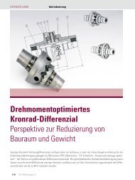
Getriebemotor mit Einscheiben-Federkraftbremse<br />
BOCKWOLD T<br />
1 Ankerscheibe 6 Einstellring<br />
Armature Plate Adjustment Ring<br />
2 Druckfeder 7 Hülsenschraube<br />
Pressure Spring Adjustment Sleeve<br />
3 Bremsrotor 8 Handlüfthebel (wahlweise)<br />
Brake Rotor Manual Release (optional)<br />
4 Nabe 10 Staubschutzring (wahlweise)<br />
Hub Dust Seal (optional)<br />
5 Magnetteil 11 Befestigungsschraube<br />
Stator Fastening Screw<br />
s Lü Luftspalt<br />
Air Gap<br />
Function<br />
Spring brakes are single-disk brakes with two friction<br />
surfaces, one of them being always the armature plate (1).<br />
The brake torque is frictionally generated by several<br />
pressure springs (2). The release of the brake is an<br />
electromagnetic procedure. During the braking process,<br />
the rotor (3), which can be moved axially on the hub (4), is<br />
pressed against the friction surface by pressure springs<br />
(2), via the armature plate (1). The transmission of the<br />
brake torque between the hub (4) and the rotor (3) is<br />
effected by means of a toothing.<br />
When the brake is engaged, you will find the air gap sLÜ<br />
between the coil of the stator (5) and the armature plate<br />
(1). The brake is released by providing the necessary D.C.<br />
voltage to the stator (5). As a consequence of the resulting<br />
magnetic force, the armature plate (1) is pulled towards<br />
the stator (5), against the spring resistance. Thus, the<br />
rotor (3) is relieved of the spring resistance and can rotate<br />
freely.<br />
By unscrewing the adjustment ring (6), you can reduce the<br />
spring resistance, resulting in a smaller brake torque.<br />
Manual Release<br />
The manual release (8) enables you to release the brake<br />
manually. Supplementary assembly is possible.<br />
Maintenance<br />
Our spring brakes are nearly maintenance-free, due to<br />
their solid friction linings free of asbestos. For necessary<br />
inspections and all other maintenance details, please refer<br />
to our Technical Documentation for spring brakes.<br />
Geared Motor with integrated single-disk spring brake<br />
4 3 1 7 10 8 11 2 5 6<br />
s LÜ