Dokumentation Flachgetriebe (pdf.-File) - ASSAG :: Antriebstechnik
Dokumentation Flachgetriebe (pdf.-File) - ASSAG :: Antriebstechnik
Dokumentation Flachgetriebe (pdf.-File) - ASSAG :: Antriebstechnik

Create successful ePaper yourself
Turn your PDF publications into a flip-book with our unique Google optimized e-Paper software.
B.5 Radial- und Axialkräfte<br />
Overhung Loads and Thrust Loads<br />
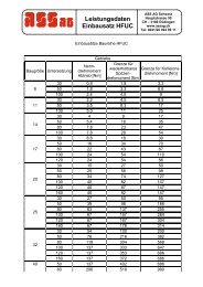
Zulässige Radialkräfte<br />
Die Angaben der zul. Radialkräfte Fr in den Leistungstabellen<br />
für <strong>Flachgetriebe</strong>motoren beziehen sich auf die<br />
Mitte des Standard-Abtriebswellenzapfens.<br />
Zulässige Axialkräfte<br />
Liegt keine Radialkraftbelastung vor, ist generell 50% der<br />
Radialkraft Fr gemäß den Leistungstabellen als Axialkraft<br />
(+ = Zug ; - = Druck) einzusetzen. Treten größere<br />
Axialkräfte FA oder kombinierte Belastungen aus<br />
Radialkraft Fr und Axialkraft FA auf, setzen Sie sich bitte<br />
mit uns in Verbindung.<br />
Radialkraftumrechnung bei außermittigem Kraftangriff<br />
Bei Kraftangriff außerhalb der Mitte des Abtriebswellenzapfens<br />
müssen die zulässigen Radialkräfte gemäß den<br />
nachfolgenden Formeln und Tabellenwerten ermittelt<br />
werden. Der kleinere der beiden Werte Fr XW (Wellenbelastung)<br />
und Fr XL (Lagerbelastung) ist der zul. Wert für die<br />
Radialkraft Fr x im Abstand " x " vom Abtriebswellenbund.<br />
Permissible Overhung Loads<br />
The permissible overhung loads Fr indicated in the<br />
selection tables for our Shaft-Mounted Geared Motors are<br />
related to the center of the standard output shaft spigot.<br />
Permissible Thrust Loads<br />
For applications without overhung loads, the permissible<br />
thrust load is always 50 % of the radial load value Fr acc.<br />
to the selection lists (+ = traction ; - = pressure). For<br />
operations under bigger thrust loads FA or combined loads<br />
consisting of overhung load Fr and thrust load FA, please<br />
contact us.<br />
Conversion of Overhung Loads at Eccentric<br />
Impact<br />
For impacts off the output shaft spigot center, the<br />
permissible overhung loads need to be determined acc. to<br />
the following formulas and tables. Please compare the<br />
values for Fr XW (shaft load) and Fr XL (bearing load). The<br />
smaller one of these two values is the permissible<br />
overhung load Fr x related to distance “x“ from output<br />
shaft collar.<br />
c<br />
Wellenbelastung Fr XW Lagerbelastung Fr<br />
a<br />
Fr � [ N]<br />
XL Fr � Fr [ N]<br />
Shaft Load XW f�<br />
x<br />
Bearing Load<br />
XL b�<br />
x<br />
Fr =<br />
Fr x.. =<br />
x =<br />
a,b,c =<br />
f<br />
zul. Radialkraft auf Mitte<br />
Abtriebswellenzapfen (x=l/2)<br />
entsprechend den Leistungstabellen<br />
für <strong>Flachgetriebe</strong>motoren.<br />
Kleinster der ermittelten<br />
Werte Fr XW und Fr XL und<br />
somit zul. Radialkraft im Abstand<br />
“x” vom Wellenbund.<br />
Abstand vom Wellenbund bis<br />
zum Kraftangriff [mm].<br />
Getriebekonstanten zur<br />
Radialkraftumrechnung<br />
Getriebekonstanten zur Radialkraftumrechnung<br />
-Beispielrechnung siehe Seite 69-<br />
Fr =<br />
Fr x.. =<br />
x =<br />
a,b,c =<br />
f<br />
Permisible overhung load on<br />
center of output shaft spigot<br />
(x=l/2), acc. to our selection<br />
tables for Shaft-Mounted<br />
Geared Motors.<br />
Smaller value of Fr XW and Fr<br />
XL , thus permissible overhung<br />
load related to distance<br />
“x” from output shaft collar.<br />
Distance between shaft collar<br />
and point of impact [mm].<br />
Gear Box constants for<br />
overhung load conversion<br />
Gear Box Constants for Overhung Load Conversion<br />
-For an example please see page 69-<br />
Getriebegröße<br />
Gear Box Size<br />
a b c f ø d x l<br />
[ CB-SF ] [ mm ] [ mm ] [ N mm ] [ mm ] [ mm ]<br />
150 98,0 78,0 9,92 x 10 4<br />
350 125,5 90,5 2,94 x 10 5<br />
450 139,5 99,5 4,56 x 10 5<br />
950 173,5 133,5 5,52 x 10 5<br />
1550 207,0 137,0 2,22 x 10 6<br />
3050 246,0 176,0 2,84 x 10 6<br />
4750 295,5 210,6 3,66 x 10 6<br />
F<br />
A<br />
O d<br />
Fr X Fr<br />
l<br />
x<br />
l/2<br />
12,0 ø 20 x 40<br />
0,0 ø 30 x 70<br />
0,0 ø 35 x 80<br />
0,0 ø 40 x 80<br />
17,0 ø 60 x 140<br />
0,0 ø 70 x 140<br />
0,0 ø 80 x 170