A formal description of SYSTEM/360
A formal description of SYSTEM/360
A formal description of SYSTEM/360
- No tags were found...
You also want an ePaper? Increase the reach of your titles
YUMPU automatically turns print PDFs into web optimized ePapers that Google loves.
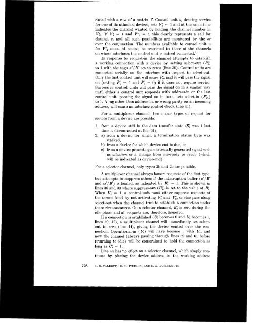
ciated with a MW <strong>of</strong> a matrix V. Control unit u, desiring servicefor one <strong>of</strong> its attached devices, sets Vi = 1 and at the same timeindicates the channel wanted by holding the channel number inVy,. If V;4 = 1 and Vt;, = c, this clearly represents a call forchannel c, and all such possibilities are monitored by the orover the conjunction. The numbers available to control unit ufor Vy, must, <strong>of</strong> course, be restricted to those <strong>of</strong> the channelson whose interfaces the control unit is indeed connected.'In response to request-in the channel attempts to establisha working connection with a device by setting select-out (PG)to 1 with the tags a"/ U set to zeros (line 39). Control units areconnected serially on the interface with respect to select-out.Only the first control unit will sense Pi, and it will pass the signalon (setting PE = 1 and Pg = 0) if it does not require service.Successive control units will pass the signal on in a similar wayuntil either a control unit responds with address-in or the lastcontrol unit, passing the signal on in turn, sets select-in (P&)to 1. A tag other than address-in, or wrong parity on an incomingaddress, will cause an interface control check (line 41).For a multiplexor channel, two major typesservice from a device are possible:<strong>of</strong> request for1. from a device still in the data transfer state (Sg was 1 lasttime it disconnected at line 61) ;2. a) from a device for which a termination status byte wasstacked,b) from a device for which device end is due, orc) from a device presenting an externally generated signal suchas attention or a change from not-ready to ready (whichwill be indicated as device-end) .For a selector channel, only types 2b and 2c are possible.A ndtiplexor channel always honors requests <strong>of</strong> the first type,but attempts to suppress others if the illterruption buffer (ax//"and os/ Bo) is loaded, as indicated by B: = 1. This is shown inis set to the value <strong>of</strong> Bg.lines 36 and 39 where suppress-out ( q)When e = I, a control unit must eithersuppress requests <strong>of</strong>'the second kind by not activating Vl and Vr2 or else pass alongselect-out when the channel tries to establish a connection underthese circumstances. On a selector channel, BE is zero during theidle phase and all requests are, therefore, honored.If a connection is established (Q becomes 0 and lJi becomes 1,lines 40, 42), a lnultiplexor channel will immediately set selectoutto zero (line 44), giving the devicc control over the connection.Operational-in (q) will have become 1 with U;, andnow the channel (always passing through lines 59 and 61 beforereturning to idle) will be constrained to hold the connection aslong as 17: = 1.Line 44 has no effect on a selector channel, which simply continuesby placing the device address in the working address228 A. D. FALKOFF, K. E. IVERSON, AND E. H. SUSSENGUTH


