A formal description of SYSTEM/360
A formal description of SYSTEM/360
A formal description of SYSTEM/360
- No tags were found...
You also want an ePaper? Increase the reach of your titles
YUMPU automatically turns print PDFs into web optimized ePapers that Google loves.
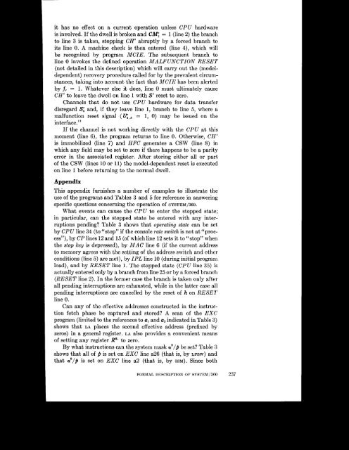
Iithas no effect on a current operation unless CPU hardwareis involved. If the dwell is broken and C m = 1 (line 2) the branchto line 3 is taken, stopping CH” abruptly by a forced branch toits line 0. A machine check is then entered (line 4), which willbe recognized by program MCIE. The subsequent branch toline 0 invokes the defined operation MALFUNCTION RESET(not detailed in this <strong>description</strong>) which will carry out the (modeldependent)recovery procedure called for by the prevalent circumstances,taking into account the fact that MCIE has been alertedby fc = 1. Whatever else it does, line 0 must ultimately causeCH” to leave the dwell on line 1 with So reset to zero.Channels that do not use CPU hardware for data transferdisregard Si and, if they leave line 1, branch to line 5, where amalfunction reset signal ( e,5 = 1, 0) may be issued on theinterface.”If the channel is not working directly with the CPU at thismoment (line 6), the program returns to line 0. Otherwise, CH“is immobilized (line 7) and HFC generates a CSW (line 8) inwhich any field may be set to zero if there happens to be a parityerror in the associated register. After storing either all or part<strong>of</strong> the CSW (lines 10 or 11) the model-dependent reset is executedon line 1 before returning to the normal dwell.AppendixThis appendix furnishes a number <strong>of</strong> examples to illustrate theuse <strong>of</strong> the programs and Tables 3 and 5 for reference in answeringspecific questions concerning the operation <strong>of</strong> <strong>SYSTEM</strong>~~O.What events can cause the CPU to enter the stopped state;in particular, can the stopped state be entered with any interruptionspending? Table 3 shows that operating state can be setby CPU line 34 (to “stop” if the console rate switch is not at “process”),by CP lines 12 and 15 (<strong>of</strong> which line 12 sets it to “stop” whenthe stop key is depressed), by MAC line 6 (if the current addressto memory agrees with the setting <strong>of</strong> the address switch and otherconditions (line 5) are met), by IPL line 10 (during initial programload), and by RESET line 1. The stopped state (CPU line 3.5) isactually entered only by a branch from line 25 or by a forced branch(RESET line 2). In the former case the branch is taken only afterall pending interruptions are exhausted, while in the latter case allpending interruptions are cancelled by the reset <strong>of</strong> h on RESETline 0.Can any <strong>of</strong> the effective addresses constructed in the instructionfetch phase be captured and stored? A scan <strong>of</strong> the EXCprogram (limited to the references to a1 and a2 indicated in Table 3)shows that LA places the second effective address (prefixed byzeros) in a general register. LA also provides a convenient means<strong>of</strong> setting any register R”‘ to zero.By what instructions can the system mask a’/# be set? Table 3shows that all <strong>of</strong> p is set on EXC line a26 (that is, by LPSW) and


