In line 121 a multiplexor channel sets P" to zero. If HIO haslasted to this point, it implies that the device is able to acceptthe order to disconnect, and line 122 branches to line 151 to issuethis order. The terms Bi and go in line 122 ensure that this istruly HIO and not a fortuitous value <strong>of</strong> P during command chainingor interruption service.The command byte is specified in line 123 in preparation forits transmission to the device in line 124. The last terms <strong>of</strong> line123 ensure that, regardless <strong>of</strong> the command code in CC, a programmingerror (Si = 1) carried over from line 112 will cause anall-zero byte (the interface command code for TIO or interruptionservice) to be transmitted. The only legitimate response to acommand code is a status byte with correct parity (line 126)and, when this response arrives (within the allowed time-outlimit), the program branches (line 127) to line 153 for CPU service.At line 153 the possibility <strong>of</strong> an interruption pending in thesubchannel is checked. This could arise either because line 153was entered directly from line 92 by a selector channel, as notedearlier, or because the special condition for a multiplexor channelin line 92 had been satisfied. In both cases a TIO must be in progressand a full CSW is stored in line 154. For a selector channelthe interruption pending in the subchannel nlust have also beenpending in the channel, and so both are cleared in line 155. For amultiplexor channel, however, the subchannel interruption couldnot have been in the channel, or the branch from line 88 to line 136would have been taken before reaching line 93, so in this case(c = 0) the state <strong>of</strong> Bi is left untouched. Line 155 is followed byline 160, which releases the device. The need for an interfacesignal is obvious for a multiplexor channel because the status hasjust been transmitted; and, for the selector channel, it will berecalled that the interruption was entered in line 74 and simplyheld by the channel with no return signal to the device at that time.The sequence just described, and the sequence 88, 136,137, .. both relate to the formation <strong>of</strong> a CSW with terminationstatus. The latter sequence, which obtains only in a multiplexorchannel, may also be followed for a pci while the subchannel isstill working. In this case the combination Si = S: = 1 would,as usual, be the result <strong>of</strong> a prior HIO, and it would be improperto reset S: in line 137. But B: is unconditionally reset, providinga double contrast with the action in line 155. In both line 136 andline 154 the count field <strong>of</strong> the CSW is indeterminate if there hasbeen a program or protection check, and in line 136 this is alsotrue for a pci.If Sg = 0 in line 153, further possibilities are checked in line156. If this is not interruption service (go = 0), and there hasbeen no programming error (Si = 0), and either the status byteon the interface (us/Uc) is all zero or this is SIO with commandchaining indicated, and the status byte conforms to one <strong>of</strong> threeallowable patterns, then the branch is taken to line 161. Otherwisethe case is either interruption service to clear a non-termina-
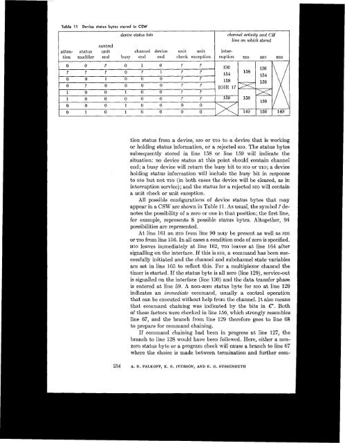
Table 11Device status bytes stored in CSWdevice status bits channel activity CH andline on which storedcontrolatten- status unit channel device unit unit intertionmodifier end busy end end check exception ruption TIO SIO HIOtion status from a device, SIO or TIO to a device that is workingor holding status information, or a rejected SIO. The status bytessubsequently stored in line 158 or line 159 will indicate thesituation: no device status at this point should contain channelend; a busy device will return the busy bit to SIO or TIO; a deviceholding status information will include the busy bit in responseto SIO but not TIO (in both cases the device will be cleared, as ininterruption service); and the status for a rejected SIO will containa unit check or unit exception.All possible configurations <strong>of</strong> device status bytes that mayappear in a CSW are shown in Table 11. As usuaI, the symbol 2 denotesthe possibility <strong>of</strong> a zero or one in that position; the first line,for example, represents 8 possible status bytes. Altogether, 94possibilities are represented.At line 161 an HIO from line 90 may be present as well as SIOor TIO from line 156. In all cases a condition code <strong>of</strong> zero is specified.HIO leaves immediately at line 162, TIO leaves at line 164 aftersignalling on the interface. If this is SIO, a command has been successfullyinitiated and the channel and subchannel state variablesare set in line 165 to reflect this. For a multiplexor channel thetimer is started. If the status byte is all zero (line 129), service-outis signalled on the interface (line 130) and the data transfer phaseis entered at line 59. A non-zero status byte for SIO at line 129indicates an immediate command, usually a control operationthat can be executed without help from the channel. It also meansthat command chaining was indicated by the bits in c". Both<strong>of</strong> these factors were checked in line 156, which strongly resemblesline 67, and the branch from line 129 therefore goes to line 68to prepare for command chaining.If commandchaining had been in progress at line 127, thebranch to line 128 would have been followed. Here, either a nonzerostatus byte or a program check will cause a branch to line 67where the choice is made between termination and further com-234 A. D. FALKOFF, K. E. IVERSON, AND E. H. SUSSENGUTH