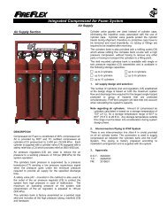
<strong>ICAF</strong> - Integrated Compressed Air Foam <strong>System</strong>Foam SupplyFoam concentrate is stored inside a stainless steel pressurevessel type tank as described in the Foam Supply Section.There are two interconnection lines provided on all foamstorage tanks. One connection is used to pressurize thefoam storage tank <strong>with</strong> compressed air (circled item 3) onalarm condition, the other to provide foam concentrate to themixing chamber (circled item 2). Piping between the foamstorage tank and the <strong>ICAF</strong> <strong>System</strong> is factory preparedaccording to the installation arrangement and is supplied <strong>with</strong>the system.<strong>System</strong> SupervisionThe ARC-1 <strong>release</strong> control panel supervises the air andwater supplies to insure system's reliability at all times.A high pressure transducer (C7) is provided to supervisecylinder bank pressure. The intent of this device is to providea supervisory signal if the cylinder bank pressure goes underthe minimum pressure required to provide air supply for thespecified discharge time. A cylinder bank pressure under2200 psi (15,158 kPa) will cause the controller to go in asupervisory alarm mode.An alarm pressure switch (B15) is provided <strong>with</strong> an alarm testvalve (B5) and a drain valve (B6). The alarm pressure switchis operated through the system's water alarm line when thesystem is discharged. <strong>System</strong> actuation, manual orautomatic, will cause the control panel to go under alarm andflow confirmation modes.The main control valve (B10) is supervised from abnormalposition by an integrated supervisory switch. Thesupervisory switch supervises the valve in an open positionand will cause the controller to go in a supervisory alarmmode in case the main control valve is not in a completelyopen position.Release <strong>System</strong>sThe system can be activated manually, <strong>electric</strong>ally usingsolenoid valves or pneumatically using a pilot line. When<strong>electric</strong>ally activated, the solenoid valves are controlled byFireFlex's ARC-1 <strong>release</strong> controller listed for releasing andcompatible <strong>with</strong> the solenoid valves. Electric Fail Safe Release:Electrically controlled <strong>ICAF</strong> <strong>System</strong>s require an <strong>electric</strong>Solenoid Valve (R2) controlled by the Approved ARC-1Control Panel <strong>with</strong> compatible detection devices (ifprovided <strong>with</strong> this system, see Controls Section fordetails). The <strong>Failsafe</strong> mode maintains the systemactivated in case of total power failure (AC and DC) of the<strong>release</strong> control panel. An emergency <strong>release</strong> valve (R1)is provided for manual override in case of a malfunction ofthe <strong>release</strong> control panel.In fire condition, when the detection condition is satisfiedthe ARC-1 Control Panel energizes the SolenoidValve (R2) open, the pneumatic control line is thenpressurized causing the water, air and foampneumatically activated control valves (A1, B9 & F1) toopen simultaneously and generate the CAF through apiping system into the discharge devices and to beGeneral SectionPage 3 of 10discharged over the area served by the dischargedevices. Electric Release:Electrically controlled <strong>ICAF</strong> <strong>System</strong>s require an <strong>electric</strong>Solenoid Valve (R2) controlled by the Approved ARC-1Control Panel <strong>with</strong> compatible detection devices (ifprovided <strong>with</strong> this system - see Controls Section fordetails). An emergency <strong>release</strong> valve (R1) is provided formanual override in case of a malfunction of the <strong>release</strong>control panel.In fire condition, when the detection condition is satisfiedthe ARC-1 Control Panel energizes the SolenoidValve (R2) open, the pneumatic control line is thenpressurized causing the water, air and foampneumatically activated control valves (A1, B9 & F1) toopen simultaneously and generate the CAF through apiping system into the discharge devices and to dischargeover the area served by the discharge devices. Pneumatic Release:Pneumatically controlled <strong>ICAF</strong> <strong>System</strong>s require apneumatic <strong>release</strong> system, equipped <strong>with</strong> fixedtemperature <strong>release</strong>s, and/or pilot heads. An emergency<strong>release</strong> valve (R1) is provided for manual override in caseof a malfunction of the <strong>release</strong> line.Release trim, for pneumatically controlled <strong>ICAF</strong> <strong>System</strong>sutilizes a Pneumatic Actuator (R5) normally held closedby pressure maintained in the pneumatic <strong>release</strong> system.The air supply for the pneumatic <strong>release</strong> piping system isprovided by the cylinders bank installed as part of the<strong>ICAF</strong> <strong>System</strong> unit. It is recommended to provideInspectors Test Connections on the <strong>release</strong> system.In fire condition, the low pressure resulting in theoperation of the pneumatic <strong>release</strong> system causes thePneumatic Actuator (R5) to open, the pneumatic controlline is then pressurized causing the water, air and foampneumatically operated control valves (A1, B9 & F1) toopen simultaneously and generate the CAF through apiping system into the discharge devices and to dischargeover the area served by the discharge devices. Manual Release.Manually actuated <strong>ICAF</strong> <strong>System</strong>s provide a manualmeans for the user to actuate the system. Manualactuation is accomplished by turning the manual <strong>release</strong>valve (R1) in the open position (identified "EmergencyRelease" on the front of the unit).In fire condition, by turning the "Emergency Release"valve in the open position the user will cause thepneumatic control line to pressurize, causing the water,air and foam pneumatically operated control valves (A1,B9 & F1) to open simultaneously and generate the CAFthrough a piping system into the discharge devices and todischarge over the area served by the discharge devices.FM-0723-0-07 C
Page 4 of 10<strong>ICAF</strong> - Integrated Compressed Air Foam <strong>System</strong>General SectionInstallation<strong>ICAF</strong> <strong>System</strong>s shall be located, installed, or suitablyprotected so as to not be subjected to mechanical, chemical,or other damage that could render them inoperative. Foamconcentrates are subject to freezing or deterioration fromprolonged storage at high temperatures, the system shalltherefore be located in a room <strong>with</strong> ambient temperaturebetween 40 ° F to 110 ° F (4 ° C to 43 ° C).Although it is preferable to locate the system outside theprotected area, in the case where there is no otheralternative, provisions should be made to ensure that thesystem is not going to be exposed to fire or mechanicaldamage in a manner that would affect its operation.<strong>System</strong>s shall also be installed so that inspection, testing,recharging, and other maintenance are facilitated andinterruption to protection is held to a minimum.1. Install the <strong>ICAF</strong> <strong>System</strong> unit, cylinders bank and foamconcentrate tank according to the technical datasupplied.Note: The drain collector shall be connected to an opendrain. Do not restrict or reduce drain piping.2. Install the open nozzles piping network in accordance<strong>with</strong> the <strong>ICAF</strong> <strong>System</strong>'s Design Manual (FM-090M-0-01).3. Install the releasing piping (if applicable), detection andsignaling circuits in accordance <strong>with</strong> applicable NFPAstandards.4. Conform to local municipal or other codes regardinginstallations of fire protection systems.5. Perform preliminary inspection outlined below prior toputting system in service.6. Put the system into operation as outlined below.7. Perform the annual inspection sequence and test eachdetector and alarm unit.8. If the system does not operate as it should, make thenecessary corrections according to manuals issued orconsult your distributor or FireFlex <strong>System</strong>s Inc.9. Make sure that the building owner or a delegatedrepresentative has received instructions regarding theoperation of the system.Preliminary inspection before placing thesystem in service(Refer to TRIM SCHEMATIC section)1. Open door to mechanical section. Main Water SupplyControl Valve (B10) should be CLOSED. Primingvalve (B1) must be CLOSED. Air supply must beCLOSED (see AIR SUPPLY SECTION). Flow TestValve (B6) and main drain valve (B16) must beCLOSED. Alarm test valve (B5) must be CLOSED.Emergency Release valve (R1) is CLOSED. <strong>System</strong>flushing valve (A3) and foam injector flushing valve (F5)must be CLOSED. All gauges (B11, B12, B17 and F4)should show 0 psi pressure.2. Connect all detection and alarm audible devices(provided by others) according to <strong>electric</strong>al schematics(see field wiring diagrams in SYSTEM WIRING section).3. Connect the AC power for the control panel on aseparate circuit breaker in the <strong>electric</strong> distribution panel(see TBA field wiring diagram in SYSTEM WIRINGsection).Note: Do not use these circuit breakers for other parallelapplications. If necessary, equip each circuit breaker <strong>with</strong>a security seal in order to avoid accidental closing.4. After the system is set, operation of the system willrequire the pressurization of the actuation line to openthe pneumatically operated control valves. This may beby automatic or manual operation of one of the <strong>release</strong>systems described above. For specific trimarrangement, refer to TRIM SCHEMATIC section.Note: Electric Release: Solenoid valves, system controlpanels and <strong>electric</strong>al detectors must be compatible.Consult ARC-1 Installation & Operation ManualFM-072Z-0-01 for devices compatibility charts.Placing the system in service:(Refer to TRIM SCHEMATIC section)1. Verify the following:a) The system Main Water Supply Control Valve (B10)is CLOSED.b) The system has been properly drained.c) Flow Test Valve (B6) is OPEN.d) The Emergency Release Valve (R1) is CLOSED.e) The system water supply piping is pressurized up tothe CLOSED Main Water Supply Valve (B10) andthe priming line is pressurized up to the CLOSEDPriming Valve (B1).f) The system flushing valve(s) (A3) is(are) CLOSED.g) The foam injector flushing valve (F5) is CLOSED.2. Verify that all releasing devices are set and that auxiliarydrain valves are CLOSED.a) OPEN Priming Valve (B1).3. OPEN Main Drain Valve(s) (B16).4. PARTIALLY OPEN Main Water Supply ControlValve (B10).5. When full flow develops from the Flow Test Valve (B6),CLOSE the Flow Test Valve.a) Verify that there is no flow from the open Main DrainValve (B16).6. CLOSE Main Drain Valve(s) (B16).7. FULLY OPEN and secure the Main Water SupplyControl Valve (B10).8. Verify that the Alarm Test Valve (B5) is CLOSED andthat all other valves are in their "normal" operatingposition.FM-0723-0-07 C