ICAF System with electric Failsafe release - FIREFLEX SYSTEMS
ICAF System with electric Failsafe release - FIREFLEX SYSTEMS
ICAF System with electric Failsafe release - FIREFLEX SYSTEMS
- No tags were found...

Create successful ePaper yourself
Turn your PDF publications into a flip-book with our unique Google optimized e-Paper software.
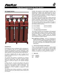
<strong>ICAF</strong> - Integrated Compressed Air Foam <strong>System</strong><strong>System</strong> Trim SectionPage 1 of 4<strong>ICAF</strong> <strong>System</strong> <strong>with</strong> Electric Fail-safe Release1. DescriptionThe <strong>ICAF</strong> <strong>System</strong> utilizes a Flow Control valve (B14) tocontrol water flow into system piping equipped <strong>with</strong> openrotating spray nozzles. The system piping remains emptyuntil the Flow Control Valve is activated by operation of the<strong>release</strong> system.In fire condition, when the detection condition is satisfied theARC-1 Control Panel energizes the Solenoid Valve (R2)open, the pneumatic control line is then pressurized causingthe water, air and foam pneumatically activated controlvalves (A1, B9 & F1) to open simultaneously and generatethe CAF through a piping system into the discharge devicesand to be discharged over the area served by the dischargedevices.Electric Fail-Safe Release means that if the AC Power failsand the battery backup expires while the system is operating,the system will fail-safe, and continue flowing until AC Poweris restored or the system is manually shut-off2. Normal conditions1. ARC-1 Control panel of the <strong>ICAF</strong> <strong>System</strong>:a) Green LAMP for power is activated in continuousmanner.b) All other LAMPS are deactivated.c) Alpha-numeric Display shows default screen" SYSTEM NORMAL"2. Valves:a) Main water supply control valve (B10) is OPEN.b) All upstream water supply valves are OPEN.c) Priming valve (B1) is OPEN.d) Flow test valve (B6) is CLOSED.e) <strong>System</strong> main drain valves (B16) are CLOSED.f) Alarm test valve (B5) is CLOSED.g) Manual emergency <strong>release</strong> valve (R1) is CLOSED(handle in NORMAL position).h) <strong>System</strong> flushing valve (A3) is CLOSED.i) Foam injector flushing valve (F5) is CLOSED.j) All gauge valves are OPEN.3. Gauges:a) Water supply (B12) - at water supply pressureb) Priming chamber (B11) - should be equal to, orhigher than, water supply pressure (B12).c) Air supply pressure (A4) is between 100-135 psi.d) Foam injection line pressure is 0 psi.4. Air supply:a) Air supply is in NORMAL condition (see Air Supplysection for details).5. Foam supply:a) Foam supply is in NORMAL condition (see FoamSupply section for details).REFER TO NEXT PAGE TO VIEW TRIM SCHEMATIC.FM-0723-0-10 A