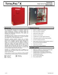
ICAF System with electric Failsafe release - FIREFLEX SYSTEMS
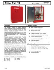
ICAF System with electric Failsafe release - FIREFLEX SYSTEMS
ICAF System with electric Failsafe release - FIREFLEX SYSTEMS
- No tags were found...

You also want an ePaper? Increase the reach of your titles
YUMPU automatically turns print PDFs into web optimized ePapers that Google loves.
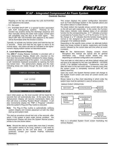
Page 4 of 8<strong>ICAF</strong> - Integrated Compressed Air Foam <strong>System</strong>Controls SectionPressing on the key will illuminate the LOG ACTIVATEDLED adjacent to the switch.- F2: Not used.- F3: SYSTEM SHUT-OFF is a special function associated<strong>with</strong> <strong>ICAF</strong> Extinguishing systems. Pressing on thisfunction key anytime during the discharge sequence andthen manually closing the water main supply control valvewill completely stop the flow of the foam agent. TheSHUT-OFF KEY ACTIVATED LED adjacent to the switchwill be illuminated while the function is active.Typically, to activate any function press and hold the key for2 seconds. Press and hold the key again to return to itsnormal status. Key status will also be indicated on the alphanumericdisplay bottom section as described earlier.5. Local Alphanumeric DisplayThe ARC-1 ® Analog Release Controller is provided <strong>with</strong> alocal Alphanumeric Display, Model LAA, mounted on thefront door that provides detailed indications for status display,operation and programming of the system. It is provided <strong>with</strong>a soft membrane keyboard accessible by opening the frontkey locked door. The alphanumeric display and the mainindicating lamps are visible through the door window at alltimes.Upon initial power up, the local sounder will be heard for 2seconds then will automatically stop. At the same time, theAlphanumeric Display will become momentarily blank andthen will show a scrolling "<strong>System</strong> Reset" indication. It willalso momentarily display the "P&P in Progress" indicationwhile the system's Plug and Play routine is executed.Note: The Plug & Play routine is automatically verifyingsystem integrity and module placement at both the initialstart-up and system reset.The start-up procedure should last only a few seconds, afterwhich, if the system is back under normal condition, theAlphanumeric Display will show the <strong>System</strong> Normal screen,similar to the one shown below:Note: Should the start-up routine take more than 2 minutesand system seems to be hung, perform a cold reset byremoving power to the unit and back. If problemcontinues, contact your nearest FireFlex AuthorizedDistributor.This screen displays the system configuration descriptionsuch as Fixed Discharge <strong>System</strong> in the example above andthe system status in a black window.The black bottom line typically shows current date and timeon the left and right respectively. In the center, the FunctionKeys status indicator code displays status of an activatedfunction for the corresponding key: A "1" indicates a functionis activated by Function Key F1, a "2" for F2 and a "3" for F3.No change or a "0" indicates that the function key(s) is(are)normal or not, assigned to any special function. Refer toparagraph 4 for additional details.Depending on the specific menu screen, an alternate bottomblack line shows number of alarms, supervisory and troubleevents, followed by the current date and time when an eventis present.Note: All the Alphanumeric Display screens shownthroughout this manual are typical and for generalinformation only. Actual screen details may varydepending on selected configuration and conditions.Time and date on initial start-up will show default values andwill have to be adjusted by the user (see MENUS – ACCESSLEVEL 2 for detailed instructions). Furthermore, time anddate will return to the last event values in memory every timethe system power is completely removed (both AC andbattery stand-by).Upon any event, the <strong>System</strong> Normal screen will change tothe <strong>System</strong> Event screen and show all current events andtheir status.Shown below is a flow chart describing in which order thesystem keys must be operated in case of various events:SINGLE EVENT OPERATION:NEW EVENT ACKNOWLEDGE RESETMULTI EVENTS OPERATION:EVENTS:ALARMSUPERVISORYTROUBLEACKNOWLEDGEALARM(S)ACKNOWLEDGESUPERVISORY(S)ACKNOWLEDGETROUBLE(S)(only after all eventshave been processed)RESET(only after all eventshave been processed)Here is a simulated <strong>System</strong> Event screen illustrating thevarious displays:FM-0723-0-17 B