ICAF System with electric Failsafe release - FIREFLEX SYSTEMS
ICAF System with electric Failsafe release - FIREFLEX SYSTEMS
ICAF System with electric Failsafe release - FIREFLEX SYSTEMS
- No tags were found...

You also want an ePaper? Increase the reach of your titles
YUMPU automatically turns print PDFs into web optimized ePapers that Google loves.
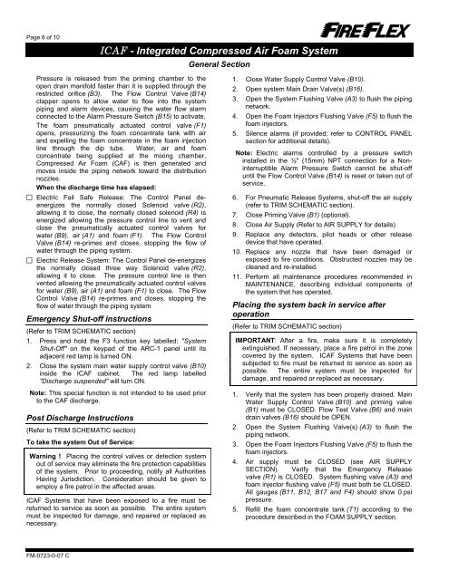
Page 6 of 10<strong>ICAF</strong> - Integrated Compressed Air Foam <strong>System</strong>General SectionPressure is <strong>release</strong>d from the priming chamber to theopen drain manifold faster than it is supplied through therestricted orifice (B3). The Flow Control Valve (B14)clapper opens to allow water to flow into the systempiping and alarm devices, causing the water flow alarmconnected to the Alarm Pressure Switch (B15) to activate.The foam pneumatically actuated control valve (F1)opens, pressurizing the foam concentrate tank <strong>with</strong> airand expelling the foam concentrate in the foam injectionline through the dip tube. Water, air and foamconcentrate being supplied at the mixing chamber,Compressed Air Foam (CAF) is then generated andmoves inside the piping network toward the distributionnozzles.When the discharge time has elapsed: Electric Fail Safe Release: The Control Panel deenergizesthe normally closed Solenoid valve (R2),allowing it to close, the normally closed solenoid (R4) isenergized allowing the pressure control line to vent andclose the pneumatically actuated control valves forwater (B9), air (A1) and foam (F1). The Flow ControlValve (B14) re-primes and closes, stopping the flow ofwater through the piping system. Electric Release <strong>System</strong>: The Control Panel de-energizesthe normally closed three way Solenoid valve (R2),allowing it to close. The pressure control line is thenvented allowing the pneumatically actuated control valvesfor water (B9), air (A1) and foam (F1) to close. The FlowControl Valve (B14) re-primes and closes, stopping theflow of water through the piping systemEmergency Shut-off instructions(Refer to TRIM SCHEMATIC section)1. Press and hold the F3 function key labelled: "<strong>System</strong>Shut-Off" on the keypad of the ARC-1 panel until itsadjacent red lamp is turned ON.2. Close the system main water supply control valve (B10)inside the <strong>ICAF</strong> cabinet. The red lamp labelled"Discharge suspended" will turn ON.Note: This special function is not intended to be used priorto the CAF discharge.Post Discharge Instructions(Refer to TRIM SCHEMATIC section)To take the system Out of Service:Warning ! Placing the control valves or detection systemout of service may eliminate the fire protection capabilitiesof the system. Prior to proceeding, notify all AuthoritiesHaving Jurisdiction. Consideration should be given toemploy a fire patrol in the affected areas.<strong>ICAF</strong> <strong>System</strong>s that have been exposed to a fire must bereturned to service as soon as possible. The entire systemmust be inspected for damage, and repaired or replaced asnecessary.1. Close Water Supply Control Valve (B10).2. Open system Main Drain Valve(s) (B16).3. Open the <strong>System</strong> Flushing Valve (A3) to flush the pipingnetwork.4. Open the Foam Injectors Flushing Valve (F5) to flush thefoam injectors.5. Silence alarms (if provided; refer to CONTROL PANELsection for additional details).Note: Electric alarms controlled by a pressure switchinstalled in the ½" (15mm) NPT connection for a NoninterruptibleAlarm Pressure Switch cannot be shut-offuntil the Flow Control Valve (B14) is reset or taken out ofservice.6. For Pneumatic Release <strong>System</strong>s, shut-off the air supply(refer to TRIM SCHEMATIC section).7. Close Priming Valve (B1) (optional).8. Close Air Supply (Refer to AIR SUPPLY for details).9. Replace any detectors, pilot heads or other <strong>release</strong>device that have operated.10. Replace any nozzle that have been damaged orexposed to fire conditions. Obstructed nozzles may becleaned and re-installed.11. Perform all maintenance procedures recommended inMAINTENANCE, describing individual components ofthe system that has operated.Placing the system back in service afteroperation(Refer to TRIM SCHEMATIC section)IMPORTANT: After a fire, make sure it is completelyextinguished. If necessary, place a fire patrol in the zonecovered by the system. <strong>ICAF</strong> <strong>System</strong>s that have beensubjected to fire must be returned to service as soon aspossible. The entire system must be inspected fordamage, and repaired or replaced as necessary.1. Verify that the system has been properly drained. MainWater Supply Control Valve (B10) and priming valve(B1) must be CLOSED. Flow Test Valve (B6) and maindrain valves (B16) should be OPEN.2. Open the <strong>System</strong> Flushing Valve(s) (A3) to flush thepiping network.3. Open the Foam Injectors Flushing Valve (F5) to flush thefoam injectors.4. Air supply must be CLOSED (see AIR SUPPLYSECTION). Verify that the Emergency Releasevalve (R1) is CLOSED. <strong>System</strong> flushing valve (A3) andfoam injector flushing valve (F5) must both be CLOSED.All gauges (B11, B12, B17 and F4) should show 0 psipressure.5. Refill the foam concentrate tank (T1) according to theprocedure described in the FOAM SUPPLY section.FM-0723-0-07 C