Exploring the Extreme Educator Guide pdf - ER - NASA
Exploring the Extreme Educator Guide pdf - ER - NASA
Exploring the Extreme Educator Guide pdf - ER - NASA
- No tags were found...

You also want an ePaper? Increase the reach of your titles
YUMPU automatically turns print PDFs into web optimized ePapers that Google loves.
National Aeronautics andSpace AdministrationEducational Product<strong>Educator</strong>s Grades K-8EG-2003-01-001-DFRC
ii<strong>Exploring</strong> <strong>the</strong> <strong>Extreme</strong>: An <strong>Educator</strong>’s <strong>Guide</strong>EG-2003-01-001-DFRC
Table of ContentsAcknowledgments.......................................................................................................... ivHow To Use This <strong>Guide</strong> ................................................................................................ 1F-15 ACTIVE Research Program History and Technology ............................ 3MatricesMa<strong>the</strong>matics Standards ............................................................................................ 14Science Standards .................................................................................................... 15Science Process Skills ............................................................................................. 16ActivitiesGrades K-4Lesson 1: Finding <strong>the</strong> Center of Gravity Using Rulers .......................................... 18Lesson 2: Finding <strong>the</strong> Center of Gravity Using Plumb Lines................................. 22Lesson 3: Changing <strong>the</strong> Center of Gravity Using Moment Arms ........................... 25Grades 5-8Lesson 1: Jet Propulsion ......................................................................................... 32Lesson 2: Vectoring ................................................................................................. 45Lesson 3: Center of Gravity, Pitch, Yaw ................................................................. 50Lesson 4: Fuel Efficiency ........................................................................................ 57AppendixGlossary...................................................................................................................... 64<strong>NASA</strong> <strong>Educator</strong> Resource Center Network .................................................. 78Evaluation Reply Card .......................................................................... Back Cover<strong>Exploring</strong> <strong>the</strong> <strong>Extreme</strong>: An <strong>Educator</strong>’s <strong>Guide</strong>EG-2003-01-001-DFRCiii
AcknowledgmentsThis publication was developed for <strong>the</strong> NationalAeronautics and Space Administration (Dryden FlightResearch Center) by PAT (Preservation of Aerospace Technology)Projects, Inc., with <strong>the</strong> assistance of teachers from <strong>the</strong> AntelopeValley in North Los Angeles County and Kern County ofCalifornia.Project Oversight and ManagementProject Oversight Marianne McCarthy, Ph.D.,Center Education Director, <strong>NASA</strong> DFRCProject Coordinator Michelle Davis,and Managing Editor Dryden Aerospace Education Specialist, <strong>NASA</strong> DFRCCover Design Ted Huetter,Education Multimedia Specialist, <strong>NASA</strong> DFRCSpecial thanks to Lee Duke, under whose guidance and tenure this product originated.F-15 ACTIVE WritersJudi Dana (K-4),Teacher, Tehachapi School DistrictMeri Kock (5-8),Teacher, Park View Intermediate SchoolMike Lewis (9-12),Teacher, Lancaster High SchoolBruce Peterson and Steve StowePilot Advisors, PAT Projects, Inc.Management and ProductionWayne Ottinger,Managing Director, PAT Projects, Inc.Kathy Johnston (Standards Matrix and Organization),Teacher, Pearblossom SchoolShari Gallagher-Johnson,Desktop Publishing and Graphic Designiv<strong>Exploring</strong> <strong>the</strong> <strong>Extreme</strong>: An <strong>Educator</strong>’s <strong>Guide</strong>EG-2003-01-001-DFRC
How To Use This <strong>Guide</strong>Controlled flight by humans was attempted early in <strong>the</strong> lastmillenium but only mastered for heavier-than-air vehiclesin <strong>the</strong> last century. Tremendous progress was achieved in<strong>the</strong> twentieth century in aircraft performance and missioncapability through research in flight controls, aircraftstability, and propulsion. Modern technology was appliedto aeronautics in <strong>the</strong> last century as aggressively as in o<strong>the</strong>rfields, such as medicine, communications, and geosciences.So many advances have been made, that today <strong>the</strong> demandsof performance and maneuverability for many advancedaircraft designs require extensive use of computers to aid<strong>the</strong> pilot in controlling flight.With some simple inexpensive materials, you can mount anexciting and productive unit for children that incorporatesscience, ma<strong>the</strong>matics, and technology education. Themany activities contained in this teaching guide emphasizehands-on involvement, prediction, data collection andinterpretation, teamwork, and problem solving. The guidealso contains background information about aeronauticalresearch that can help students learn how airplanes fly.Following <strong>the</strong> background sections are a series of activitiesthat demonstrate <strong>the</strong> basic science of aeronautics whileoffering challenging tasks in design. Each activity employsbasic and inexpensive materials. In each activity you willfind construction diagrams, material and tools lists, andinstructions. A brief background section within eachactivity elaborates on <strong>the</strong> concepts covered and points backto <strong>the</strong> introductory material in this guide. Also included isinformation about where <strong>the</strong> activity applies to science andma<strong>the</strong>matics standards, assessment ideas, and extensions.Because many of <strong>the</strong> activities and demonstrations apply tomore than one subject area, a matrix chart identifiesHigh Performance Learning Activities in Ma<strong>the</strong>matics, Science and TechnologyEG-2003-01-001-DFRC1
opportunities for extended learning experiences. The chartindicates <strong>the</strong>se subject areas by activity title. In addition,many of <strong>the</strong> student activities encourage student problemsolvingand cooperative learning. The length of timeinvolved for each activity varies according to its degree ofdifficulty and <strong>the</strong> development level of <strong>the</strong> students.Finally, <strong>the</strong> guide concludes with a glossary of terms,suggested reading list, <strong>NASA</strong> educational resourcesincluding electronic resources, and an evaluationquestionnaire. We would appreciate your assistance inimproving this guide in future editions by completing <strong>the</strong>questionnaire and making suggestions for changes andadditions.A Note on MeasurementIn developing this guide, metric units of measurement wereemployed. In a number of instances, English units are usedor shown along with metric units because of <strong>the</strong> standardpractices in <strong>the</strong> aviation community, such as altimetersdisplaying feet instead of meters.2High Performance Learning Activities in Ma<strong>the</strong>matics, Science and TechnologyEG-2003-01-001-DFRC
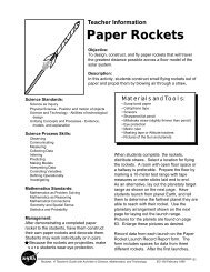
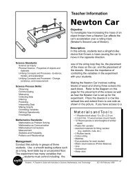
F-15 ACTIVE (Advanced Control Technology for Integrated VEhicles)Research Program History and TechnologyFigure 1-1F-15 ACTIVEThis highly modified F-15 fighter was just one of <strong>the</strong> aircraft used by <strong>NASA</strong> to explore <strong>the</strong> extremelimits of aerospace technology. The aircraft was built in 1972, and modified for <strong>the</strong> U.S. Air Force'sShort Takeoff and Landing Maneuvering Technology Demonstrator (STOL/MTD) flight researchprogram which lasted from <strong>the</strong> mid-1980s until 1991. Beginning in 1993 it was involved in a <strong>NASA</strong>,U.S. Air Force, and private industry flight research program called Advanced Control Technology forIntegrated Vehicles (ACTIVE). The F-15 ACTIVE program concluded in 1999. Since <strong>the</strong>n <strong>the</strong> aircrafthas been used as a testbed for "intelligent flight control systems" that enable a pilot to maintain controland safely land an aircraft that has suffered a major systems failure or combat damage.History and Technical DiscussionPilots can maneuver an airplane about each ofits three axes, producing motions called pitch,roll, and yaw (figure 1-2). Pilots steer <strong>the</strong>airplane’s flight path as desired by controllingpitch, roll, and yaw with a control wheel(or stick) and foot pedals located in <strong>the</strong>cockpit. These cockpit controls are in turnconnected to movable panels, called flightcontrol surfaces, attached to <strong>the</strong> airplane’sstructure. These surfaces are named <strong>the</strong>elevator, ailerons, and rudder (figure 1-3).The elevator produces pitch up or down when<strong>the</strong> pilot moves <strong>the</strong> control stick backward orforward. Ailerons cause <strong>the</strong> airplane to rollright or left corresponding to right or leftmovement of <strong>the</strong> control stick. The rudderproduces right or left yaw corresponding toright or left rudder pedal movement.A recent flight control design incorporated in<strong>the</strong> F-15 ACTIVE (figure 1-1) is <strong>the</strong> use ofthrust vectoring to also produce pitch, roll,and yaw. Here, <strong>the</strong> jet engine’s exhaust nozzleHigh Performance Learning Activities in Ma<strong>the</strong>matics, Science and TechnologyEG-2003-01-001-DFRC3
The ruddercontrols yawElevator controls pitchForceForceAilerons control rollFigure 1-2Three axes producing motions called pitch, roll, and yaw.Figure 1-3Supermarine Spitfire4High Performance Learning Activities in Ma<strong>the</strong>matics, Science and TechnologyEG-2003-01-001-DFRC
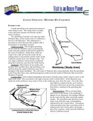
moves as well as <strong>the</strong> flight control surfaceswhen <strong>the</strong> pilot moves <strong>the</strong> control stick. Thismovable nozzle deflects <strong>the</strong> exhaust stream toproduce <strong>the</strong> desired motion. Thrust vectoringcausing a nose-up pitching motion is illustratedin figure 1-4. Deflecting <strong>the</strong> exhaust streamupward causes a reaction force that moves <strong>the</strong>tail down (and nose up), complementing <strong>the</strong>usual nose-up motion due to elevatordeflection.“Vectoring” for jets simply means pointing <strong>the</strong>engine exhaust in various directions (direction+ magnitude = vector) to change <strong>the</strong> directionof <strong>the</strong> aircraft’s flight path. You may havedriven a small boat by pointing an outboardmotor to steer <strong>the</strong> boat; it’s much <strong>the</strong> sameidea.Here is a more formal definition of thrustvectoring: <strong>the</strong> manipulation of jet engineexhaust such that <strong>the</strong> resultant reaction forcesaugment, or in some cases, replace, thoseforces normally generated by <strong>the</strong> aerodynamiccontrol surfaces.Flight Control DesignMechanical Flight ControlsFrom <strong>the</strong> Wright Flyer through most WorldWar II airplane designs, <strong>the</strong> pilot’s stick andrudder pedals were connected to <strong>the</strong> flightNose UpPitchingMomentThrust VectoringPropulsive ForceDownward(Maneuver)Forcecontrol surfaces with steel cables. Thus, <strong>the</strong>sedesigns are often called “manual” or“mechanical” flight control systems.In such a design, pressure of <strong>the</strong> airflow over<strong>the</strong> airplane’s flight control surfaces resistsmovement of <strong>the</strong> cockpit control stick. Sincefaster speeds produce higher air pressures, itbecomes progressively harder for <strong>the</strong> pilot tophysically move <strong>the</strong> stick as airspeedincreases.Hydraulic Flight ControlsTo allow <strong>the</strong> pilot to be able to move <strong>the</strong>control stick at very high speeds, hydraulicallypowered flight control systems wereintroduced. Here, a hydraulic actuator moves<strong>the</strong> control surface and essentially multipliesany force <strong>the</strong> pilot applies to <strong>the</strong> stick manytimes over as it positions <strong>the</strong> control surface.While permitting supersonic flight, hydraulicflight control systems posed new problems forpilots in controlling <strong>the</strong>se airplanes. It wasoften difficult for <strong>the</strong> pilot to predict how muchstick force was necessary to produce <strong>the</strong>desired response. Control forces, which werenatural and predictable in a mechanical flightcontrol aircraft, were reproduced artificially in<strong>the</strong> hydraulic aircraft. Optimizing <strong>the</strong> variousdevices involved over <strong>the</strong> entire flightenvelope proved difficult, and it was notuncommon for pilots of <strong>the</strong>se highlyLiftWeightFigure 1-4Pitch Thrust VectoringHigh Performance Learning Activities in Ma<strong>the</strong>matics, Science and TechnologyEG-2003-01-001-DFRC5
maneuverable aircraft to lose control.Additionally, failures of <strong>the</strong> hydraulic system,such as ruptured fluid supply lines oroverheated pumps, plagued <strong>the</strong>se designs.Fly-By-Wire Flight ControlsIn <strong>the</strong> 1960s, designers turned to electronicsand computer technologies to overcome manyof <strong>the</strong> problems associated with hydraulicallypowered flight controls. Hydraulic actuatorswere still necessary, but fly-by-wire meant that<strong>the</strong> pilot’s control stick movements were nowtransmitted electronically to <strong>the</strong> actuators.Also, a computer allowing much-improvedflight path control precision could control <strong>the</strong>airplane’s response. <strong>NASA</strong> research was <strong>the</strong>driving force for <strong>the</strong> successful development offly-by-wire aircraft.The <strong>NASA</strong> Digital Fly-By-Wire (DFBW forshort) research aircraft, a modified U.S. NavyF-8 Crusader, was one of <strong>the</strong> most significantresearch programs in <strong>NASA</strong> history. On May25, 1972, <strong>NASA</strong> 802 became <strong>the</strong> first aircraftto fly completely dependent upon an electronicflight control system (no mechanical backup).It used a computer from <strong>the</strong> Apollo spacecraftto operate <strong>the</strong> flight controls. The DFBW F-8validated <strong>the</strong> concepts of <strong>the</strong> fly-by-wire flightcontrol systems now used on nearly all modernhigh-performance aircraft, military and civiliantransports, and <strong>the</strong> Space Shuttle flight controlsystem. 1 The F-15 ACTIVE research aircraft isequipped with a digital fly-by-wire flightcontrol system.Digital flight-control systems were able toincorporate “multi-mode” flight control lawswith different modes, each optimized toenhance maneuverability and controllabilityfor a particular phase of flight. Earliermechanical or electronic flight control systemscould be optimized for only one particular setof flight conditions, such as supersonic flight,weapons carriage, or perhaps takeoff andlanding. But <strong>the</strong> DFBW designs could “flip aswitch,” giving a separate set of softwarecontrol laws for each flight phase <strong>the</strong> aircraftwould encounter. Thus, a design might have atakeoff and landing mode with its set of controllaws, a cruise mode with a different set ofcontrol laws, a weapons delivery mode,supersonic mode, and so on. Development ofthrust vectoring control laws is part of <strong>the</strong> F-15ACTIVE research.Thrust Vectoring and Fly-By-WireCombinedThrust vectoring produces greater agility andmaneuverability, especially at slow airspeedsand at a high angle-of-attack (relationshipbetween <strong>the</strong> aircraft’s wings and actual flightpath). Whereas aerodynamic control surfaceslose <strong>the</strong>ir ability to produce pitch, roll, or yawat slow airspeeds, thrust vectoring still remainsquite effective. This is because <strong>the</strong> pressure ofengine thrust against <strong>the</strong> nozzles staysrelatively constant while <strong>the</strong> air pressure oncontrol surfaces goes down exponentially asairspeed decreases. In fact, aerodynamicsurfaces can lose effectiveness altoge<strong>the</strong>r if <strong>the</strong>angle-of-attack gets too high (called a stall).Fly-by-wire computers do <strong>the</strong> job of properlyblending <strong>the</strong> amount of control surfacedeflection and thrust vectoring needed. Thisallows <strong>the</strong> pilot to simply move <strong>the</strong> stick in <strong>the</strong>desired direction, so that flying a thrustvectored airplane is no more difficult, ordifferent, than flying a conventional airplane.O<strong>the</strong>r design benefits include less drag fromelevator/stabilator deflections for balance(trim drag); that is, <strong>the</strong> use of thrust vectoringinstead of control surface deflection forbalance requirements. This in turn results inbetter fuel efficiency (due to less trim drag)and reduced operating costs. Thrust vectoringmakes possible new, more aerodynamicallyefficient configurations, such as tailless aircraft6High Performance Learning Activities in Ma<strong>the</strong>matics, Science and TechnologyEG-2003-01-001-DFRC
with reduced weight due to replacement ofcontrol surface area. Safety can be improvedby preventing stalls and loss of control andwith reconfigurable flight controls using thrustvectoring to replace a malfunctioning controlsurface. Finally, slower landing speeds arepossible, allowing shorter, less expensiverunways to be used.Related Programs and ResearchHarrier “Jump Jet” Operational ExperienceOne of <strong>the</strong> first operational aircraft to usethrust vectoring was <strong>the</strong> Harrier, flown by <strong>the</strong>British Royal Air Force, British Royal Navy,and <strong>the</strong> U.S. Marines. The first flight of <strong>the</strong>prototype, called <strong>the</strong> Kestrel, was in 1960. TheHarrier uses four movable engine exhaustnozzles that may be rotated downward, asillustrated in figure 1-5, for vertical takeoff orlanding. Its thrust vectoring capability was notdesigned for in-flight maneuvers o<strong>the</strong>r thantakeoff and landing.MATV, HARV, and X-31<strong>NASA</strong> research explored thrust vectoring atextremely high angle-of-attack on <strong>the</strong> HighAlpha (angle-of-attack) Research Vehicle(HARV), a modified F-18. The F-16 Multi-Axis Thrust Vectoring (MATV) researchprogram made significant contributions tounderstanding thrust vectoring designrequirements and agility benefits. The X-31research aircraft is continuing to help <strong>NASA</strong>learn about <strong>the</strong> benefits of thrust vectoring(figure 1-6). Whereas a small airplane likethose you might see at <strong>the</strong> local airport mightstall and lose control at about 15 degreesangle-of-attack, <strong>the</strong> X-31 has demonstratedcontrolled flight to 70 degrees angle-of-attackas well as flight with <strong>the</strong> vertical stabilizer andrudder completely removed (figure 1-7).F-15 S/MTDThe F-15 S/MTD (STOL [Short Take Off andLanding]/Maneuvering TechnologyDemonstrator) testing focused on short takeoffsand landings as well as on enhancing pitchmaneuvering capabilities. The first flight with <strong>the</strong>vectoring nozzles was in May 1989 and flighttesting lasted until late 1991. The programdemonstrated significantly shorter runwayrequirements of about 50 percent over productionF-15s, inflight use of thrust reversing fordeceleration improvement, and enhancedpitching moments with pitch thrust vectoring. 2The ACTIVE effort evolved from <strong>the</strong> S/MTDprogram at <strong>the</strong> <strong>NASA</strong> Dryden Flight ResearchCenter.F-15 ACTIVE Research ProgramThe F-15 ACTIVE research program combined<strong>the</strong> latest in fly-by-wire flight control systemand three-dimensional (3-D) thrust vectoringtechnologies. While previous programsdemonstrated one-dimensional (1D), twodimensional(2D), and three-dimensional (3D)vectoring during very slow speed, high angleof-attackconditions, <strong>the</strong> F-15 ACTIVE wasused to study <strong>the</strong> utility of thrust vectoringover a broader spectrum of flight conditions.The overall goal of <strong>the</strong> F-15 ACTIVE testprogram was to expand <strong>the</strong> flight envelope inwhich useful thrust vectoring is available toenhance aircraft performance, maneuverability,and controllability using productionrepresentative(those that could be massproducedeconomically) thrust vectoringnozzles. 3Aircraft DescriptionThe test aircraft was a USAF F-15B (two-seatversion), tail number 71-0290, and became<strong>NASA</strong> 837. This aircraft has been throughmany modifications over <strong>the</strong> years for varioustest programs so it is quite different fromproduction F-15 aircraft. It was selected for <strong>the</strong>ACTIVE research because of <strong>the</strong> flexibility ofits unique, digital, fly-by-wire, integrated flightcontrol and propulsion system. The cockpitHigh Performance Learning Activities in Ma<strong>the</strong>matics, Science and TechnologyEG-2003-01-001-DFRC7
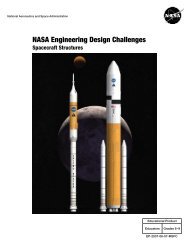
closely resembles <strong>the</strong> F-15E “glass” cockpitswith electronic flight instrument displays and awide field-of-view Head Up Display.Externally, canard flight control surfaces(actually modified F-18 stabilators) wereadded on <strong>the</strong> left and right upper inlet areasforward of <strong>the</strong> wing.Most importantly, this aircraft had specialnozzles for each of <strong>the</strong> two Pratt & Whitneyafterburning engines that can vector up to 20degrees in any direction from <strong>the</strong> thrustcenterline. 3 F-15 ACTIVE StatisticsMaximum Altitude: 65,000 ftMaximum Speed: Mach 2.0+Weight: 54,000 lbs at takeoff,46,000 lbs emptyFuel Capacity: 11,520 lbs(approximately 1,700 gal)Engines: Two Pratt & Whitney F100–PW-229thrust vectoring turbofan jet enginesEngine Nozzles: Pratt & Whitney Pitch/YawBalance Beam Nozzles (PYBBN)Wingspan: 42.10 ftLength: 63.9 ft (excluding <strong>the</strong> nose boom)Height: 18.8 ftHorizontal Tail (stabilator) Span: 28.2 ftCanard Span: 25.6 ftThe F-15 ACTIVE had nine control effectors:left canard, right canard, left aileron, rightaileron, left stabilizer, right stabilizer, rudder(two surfaces counted as one effector since<strong>the</strong>y move toge<strong>the</strong>r), pitch nozzle, and yawnozzle (figure 1-8). Flight demonstration of acomputer program that can optimize <strong>the</strong>se nineeffector movements as well as engine thrust tomaximize performance factors, such as range,is a major objective of ACTIVE. The cockpitcontrols for some <strong>the</strong>se effectors are shown infigure 1-9.ACTIVE TestingF-15 ACTIVE testing was a joint programconducted by <strong>NASA</strong>, USAF, Boeing PhantomWorks (formerly McDonnell DouglasAerospace Phantom Works), and Pratt &Whitney. As mentioned, <strong>the</strong> F-15 ACTIVEresearch used <strong>the</strong> very same aircraft as <strong>the</strong> F-15 S/MTD program. The major change to <strong>the</strong>F-15B test aircraft was <strong>the</strong> installation of Pratt& Whitney Pitch/Yaw Balance Beam Nozzles(PYBBN for short). PYBBN design hasmatured to <strong>the</strong> point where <strong>the</strong>y could be usedin a production series of aircraft. 3 The firstorder of business was to “clear <strong>the</strong> envelope”to make sure <strong>the</strong> nozzles would operate asexpected throughout <strong>the</strong> F-15 ACTIVE’s flightenvelope (figure 1-10) without causing anyunwanted side effects or engine problems.Next was to find out how well <strong>the</strong> nozzlesactually vectored engine exhaust anddetermine whe<strong>the</strong>r <strong>the</strong> additional loadsimparted to <strong>the</strong> tail end of <strong>the</strong> aircraft wereacceptable. Initial testing also evaluatedimprovements in aircraft performance due tothrust vectoring.F-15 ACTIVE flight testing commenced onFebruary 14, 1996, with <strong>the</strong> first vectoringflight, at 20,000 feet and Mach 0.6, less thanone month later, on March 7. The firstsupersonic pitch vectoring was on April 24,taking ACTIVE to Mach 1.2 at 30,000 feet.This was followed by a “world first”supersonic yaw vectoring at Mach 1.6 and45,000 feet, on June 13. By November, thrustvectoring had been performed as fast as Mach1.95 at 45,000 feet and as slow as 200 knots at30,000 feet with angle-of-attack at 30 degrees. 4Testing demonstrated successful operation of<strong>the</strong> PYBBN nozzles and problem-free engineoperation.Additional testing was done to evaluate <strong>the</strong>impact of <strong>the</strong> vectored exhaust plume onHigh Performance Learning Activities in Ma<strong>the</strong>matics, Science and TechnologyEG-2003-01-001-DFRC9
CANARDS42.83 ft.CANARDS63.75 ft.18.67 ft.Figure 1-8Control Effectors of F-15 ACTIVE10High Performance Learning Activities in Ma<strong>the</strong>matics, Science and TechnologyEG-2003-01-001-DFRC
aircraft response and stability. These jetinteraction effects were important to define forfuture aircraft designs such as <strong>the</strong> Joint StrikeFighter program. Additional tests proved that<strong>the</strong> PYBBN nozzles did not impact engineoperability and that <strong>the</strong> Pratt & Whitney designwas well suited for future ACTIVE researchobjectives. 4Included in <strong>the</strong> research experiments was anadvanced fly-by-wire flight control systemcalled “Intelligent Flight Control.” Thissystem allows <strong>the</strong> aircraft to automaticallyadapt to unforeseen changes due to failures orbattle damage to flight controls by directing<strong>the</strong> remaining control effectors to compensatefor <strong>the</strong> malfunctioning ones. This could allowfuture aircraft to safely land after sustainingmajor damage or system failures.This concludes <strong>the</strong> introduction to <strong>the</strong> F-15ACTIVE research program. You should nowhave an appreciation of aerodynamic designevolution, thrust vectoring concepts, fly-bywireflight controls, and integration of <strong>the</strong>setechnologies as <strong>the</strong>y have influenced <strong>the</strong>configuration of <strong>the</strong> F-15 ACTIVE aircraft.References1<strong>NASA</strong> Dryden Flight Research Center, 1992.F-8 Digital Fly-By-Wire Fact Sheet.Document: FS-DFRC-011 (9205), May 1992.Edwards, CA: <strong>NASA</strong> Dryden Flight ResearchCenter Public Affairs Office.2Jenschke, E. and Walker, L. 1990.F-15 STOL/Maneuvering TechnologyDemonstrator: Phase III: Thrust Vectoring,Reversing, and STOL Operations. Pp. 30–50in <strong>the</strong> SETP Thirty-Fourth SymposiumProceedings, Beverly Hills, CA, September27–29, 1990. Lancaster, CA: SETP.3Berger, C., Conners, T., Johnson, G., Orme, J.,Schkolnik, G., Shy, K., Smolka, J., Walker, L.,and Wood, C. 1996. F-15 ACTIVE ResearchProgram. Pp. 112–145 in <strong>the</strong> SETP FortiethSymposium Proceedings, Beverly Hills, CA,September 26–28, 1996. Lancaster, CA: SETP.4Bolling, J., Conners, T., Doane, P., Duke, B.,Fick, E., Orme, J., Schkolnik, G., and Wood,B. 1997. ACTIVE Thrust Vectoring WorkshopPresentations, AIAA Atmospheric MechanicsConference, New Orleans, LA, August 13,1997. (Available from AIAA, Reston, VA.)12High Performance Learning Activities in Ma<strong>the</strong>matics, Science and TechnologyEG-2003-01-001-DFRC
ActivityMatric e sHigh Performance Learning Activities in Ma<strong>the</strong>matics, Science and TechnologyEG-2003-01-001-DFRC13
Curriculum and EvaluationStandards for School Ma<strong>the</strong>maticsNational Council of Teachersof Ma<strong>the</strong>matics in 1989Ma<strong>the</strong>matics as Problem SolvingMa<strong>the</strong>matics as CommunicationMa<strong>the</strong>matics as ReasoningMa<strong>the</strong>matical ConnectionComputation and EstimationAlgebraGeometryMeasurementxxxxxxxxChanging <strong>the</strong> Center of Gravity with Moment ArmsJet PropulsionVectoringCenter of Gravity, Pitch, YawFuel EfficiencyFinding <strong>the</strong> Center of Gravity Using Plumb LinesFinding <strong>the</strong> Center of Gravity Using Rulersxxxxxxxxxxxxxxxxx14High Performance Learning Activities in Ma<strong>the</strong>matics, Science and TechnologyEG-2003-01-001-DFRC
National Science Education StandardsNational Research Council 1996 Grades 4-12Science as InquiryAbilities necessary to do scientific inquiryPhysical ScienceProperties and changes of properties in matterMotions and forcesTransfer of energyInteractions of energy and matterLife ScienceStructure and function in living systemsEarth and Space ScienceEarth in <strong>the</strong> solar systemScience and TechnologyAbilities of technological designUnderstanding about science and technologyScience in Personal and Social PerspectivesPopulations, resources, and environmentsRisks and benefitsNatural and human induced risksFinding <strong>the</strong> Center of Gravity Using RulersFinding <strong>the</strong> Center of Gravity Using Plumb LinesChanging <strong>the</strong> Center of Gravity with Moment ArmsJet PropulsionVectoringCenter of Gravity, Pitch, YawFuel EfficiencyxxxxxxxxxxxxxxxxxxxHigh Performance Learning Activities in Ma<strong>the</strong>matics, Science and TechnologyEG-2003-01-001-DFRC15
Science Process SkillsObservingCommunicationMeasuringCollecting DataInferringPredictingMaking ModelsMaking GraphsHypo<strong>the</strong>sizingInterpreting DataControlling VariablesDefining OperationallyInvestigatingxxxxxxxxxxxxxxxxxxxxFinding <strong>the</strong> Center of Gravity Using RulersChanging <strong>the</strong> Center of Gravity with Moment ArmsJet PropulsionVectoringCenter of Gravity, Pitch, YawFuel EfficiencyxxxxxxxxxFinding <strong>the</strong> Center of Gravity Using Plumb Linesxxxxxxxxxx16High Performance Learning Activities in Ma<strong>the</strong>matics, Science and TechnologyEG-2003-01-001-DFRC
Grades K - 4High Performance Learning Activities in Ma<strong>the</strong>matics, Science and TechnologyEG-2003-01-001-DFRC17
Lesson 1: Finding <strong>the</strong> Center of Gravity Using RulersGrades K–4Objectives• To discover <strong>the</strong> center of gravity (c.g.) bybalancing a cardstock shape (twodimensionalmodel) of an F-15 ACTIVEon a ruler both longitudinally and laterally.• To demonstrate balance (state ofequilibrium) by suspending a cardboardshape of an F-15 ACTIVE from a string at<strong>the</strong> center of gravity (c.g.).Science StandardsScientific EnterpriseScience and TechnologyScience as InquiryPhysical SciencePosition and Motion of ObjectsChange, Constancy, and MeasurementEvidence, Models, and ExplanationScience Process SkillsObservingCommunicatingMeasuringCollecting DataInferringPredictingHypo<strong>the</strong>sizingInvestigatingMa<strong>the</strong>matical StandardsProblem SolvingCommunicationReasoningMeasuringManagementThis lesson may be a whole class lesson. Forkindergarten and first grade students, <strong>the</strong>teacher may demonstrate using one cardstockmodel of an F-15 ACTIVE. Students in grades2-4 may each have <strong>the</strong>ir own cardstock modelor work in small groups of two to four sharinga cardstock model.This lesson is divided into two parts. In part 1,students draw longitudinal and lateral axes tofind <strong>the</strong> center of gravity. In part 2, studentsmay need help to suspend models. The modelsare needed for lesson 3, and part 2 may bepostponed until lesson 3 is scheduled. Allowapproximately 30 to 45 minutes to complete.The center of gravity is <strong>the</strong> average location of<strong>the</strong> weight of <strong>the</strong> aircraft. The mass andweight are distributed throughout <strong>the</strong> airplane.Part 1Materials and Tools• Cardstock F-15 ACTIVEs (see page 21)for each student or group• Ruler for each group• Crayon• Masking tape• ScissorsPreparationTeacher uses <strong>the</strong> pattern to trace and cut outF-15 ACTIVE models from light cardstock(see page 21). If students are capable, <strong>the</strong>ycan cut out <strong>the</strong>ir own models.Procedure1. Ask students what <strong>the</strong>y know about <strong>the</strong> F-15. (It is a highly maneuverable fightercapable of achieving Mach 2 and highaltitudes. Explain that <strong>the</strong> F-15 ACTIVEwas a special one-of-a-kind airplane flownby <strong>NASA</strong> and U.S. Air Force researchpilots for research purposes.)2. Bring out a cardstock F-15 ACTIVEmodel. Balance it flat on your finger orfist. Ask <strong>the</strong> students if <strong>the</strong>y think <strong>the</strong>ycould balance it too. If using one model todemonstrate, give several students achance to balance it, or distribute <strong>the</strong>cardstock F-15 ACTIVEs. Allow time forexperimentation.18High Performance Learning Activities in Ma<strong>the</strong>matics, Science and TechnologyEG-2003-01-001-DFRC
3. Tell students that <strong>NASA</strong> engineers need toknow <strong>the</strong> exact place to balance <strong>the</strong> realairplane, just as <strong>the</strong>y balanced <strong>the</strong>ir modelairplanes. This place is called <strong>the</strong> center ofgravity (c.g.). Balance an F-15 ACTIVEmodel on your finger. Tell students this isa stable position—when given a littlepush—it wobbles back and forth, butdoesn’t fall. It will come back to a stable,balanced position. Tell <strong>the</strong>m <strong>NASA</strong>engineers use science and ma<strong>the</strong>matics tofind <strong>the</strong> center of gravity (c.g.), and <strong>the</strong>ycan do it too.4. Tell students <strong>the</strong>y will balance <strong>the</strong> F-15ACTIVE models on <strong>the</strong> edge of a rulerinstead of on <strong>the</strong>ir fingers. Demonstratehow to position <strong>the</strong> ruler on <strong>the</strong> edge of atable and tape it in place with maskingtape.5. Most of <strong>the</strong> ruler’s length should extendpast <strong>the</strong> edge of <strong>the</strong> table.6. Demonstrate how to balance <strong>the</strong> cardstockF-15 ACTIVE on <strong>the</strong> ruler in alongitudinal direction. Draw a line down<strong>the</strong> middle of <strong>the</strong> F-15 ACTIVE with acrayon.8. The point of intersection of <strong>the</strong> two lines is<strong>the</strong> center of gravity (c.g.).Draw Line9. Distribute tape and rulers to each group.Students will tape <strong>the</strong> ruler to a desk andtake turns helping each o<strong>the</strong>r balance andhold <strong>the</strong> F-15 ACTIVE steady so linesmay be drawn. This could be a learningcenter with an adult helper. Save F-15ACTIVE for part 2.Part 2Materials and Tools• Cardstock F-15 ACTIVE from part 1• Crayons• Needle and string for teacher• Paper clips• Ceiling hooks• Meter sticks or rulersTableTapeRuler on edge7. Demonstrate how to balance <strong>the</strong> F-15ACTIVE on <strong>the</strong> ruler in a lateral direction.Draw a line.Draw LineHigh Performance Learning Activities in Ma<strong>the</strong>matics, Science and TechnologyEG-2003-01-001-DFRC19
Procedures1. Allow students to color <strong>the</strong>ir F-15ACTIVEs using <strong>the</strong> colors of red, whiteand blue. Use <strong>the</strong> <strong>Exploring</strong> <strong>the</strong> <strong>Extreme</strong>poster as a color guide or look on-line atwww.spacelink.nasa.gov. Teacher punchesa small hole in each F-15 ACTIVE at <strong>the</strong>center of gravity with <strong>the</strong> needle andthread.2. Tie a large knot on <strong>the</strong> bottom of <strong>the</strong>string. The knot must be larger than <strong>the</strong>hole.3. Hang from ceiling using paper-clip hooksor suspend from meter stick/ruler, whichwill be held by <strong>the</strong> teacher or partner. SaveF-15s for lesson 3.Assessment1. Conduct a class discussion where studentsdemonstrate <strong>the</strong>ir understanding of:• Balance• Stability• Center of gravityManagementIn part 1, students may work individually or in pairsusing <strong>the</strong>ir F-15 ACTIVE models from lesson 1 orlesson 2. Using just one suspended cardstock F-15ACTIVE model, <strong>the</strong> teacher may demonstrate part 1.In part 2, students working in pairs or groups of threewill be able to help each o<strong>the</strong>r. Allow 20–30 minutesfor part 1, and 45 minutes for part 2.DescriptionStudents discover <strong>the</strong> center of gravity of a cardstockshape of an F-15 ACTIVE using plumb lines andsuspend <strong>the</strong> F-15 ACTIVE from a string.Materials and Tools• Cardboard F-15 ACTIVEs• String for each group, 18 inches (45.72centimeters)• Hole punch for each group• 2 pushpins• Paper clip for each group• Ruler for each group2. Ask students to predict what <strong>the</strong>y thinkmight happen if <strong>the</strong> teacher pushes <strong>the</strong>F-15 ACTIVE in:• A forward direction• A sideways direction3. Push <strong>the</strong> F-15 ACTIVE and allow it toswing back to a resting position. Discuss<strong>the</strong> action in terms of balance andstability. Compare <strong>the</strong> push to a pilotflying (controlling) <strong>the</strong> airplane and <strong>the</strong>airplane being designed to return to astable position. The F-15 ACTIVE usescomputers to integrate <strong>the</strong> control surfacesand <strong>the</strong> vectored thrust so that <strong>the</strong> plane isstable.20High Performance Learning Activities in Ma<strong>the</strong>matics, Science and TechnologyEG-2003-01-001-DFRC
Drawing of F-15 ACTIVE(Teachers, copy this page on to cardstock.)High Performance Learning Activities in Ma<strong>the</strong>matics, Science and TechnologyEG-2003-01-001-DFRC21
Lesson 2: Finding <strong>the</strong> Center of Gravity Using Plumb LinesGrades 3–4Objectives• To discover <strong>the</strong> center of gravity (c.g.) of acardstock shape (two-dimensional model)of an F-15 ACTIVE using plumb line.• To demonstrate balance (state ofequilibrium) by suspending a cardstockshape of an F-15 ACTIVE from a string at<strong>the</strong> center of gravity.Science StandardsScientific EnterpriseScience and TechnologyScience as InquiryPhysical SciencePosition and Motion of ObjectsChange, Constancy, and MeasurementEvidence, Models, and ExplanationScience Process SkillsObservingCommunicatingMeasuringInvestigatingPredictingControlling VariablesMa<strong>the</strong>matical StandardsProblem SolvingCommunicatingReasoningMeasuringFunctions and Patterns22High Performance Learning Activities in Ma<strong>the</strong>matics, Science and TechnologyEG-2003-01-001-DFRC
PreparationUse <strong>the</strong> pattern of <strong>the</strong> F-15 ACTIVE to traceand cut out cardboard shapes. Older studentscan do <strong>the</strong> cutting.Part 11. Introduce <strong>the</strong> F-15 ACTIVE• Ask students what <strong>the</strong>y know about <strong>the</strong> F-15 ACTIVE. (A highly maneuverablefighter capable of achieving over Mach 2and altitudes of 60,000 feet.) Bring out oneof <strong>the</strong> cardstock F-15 ACTIVEs. Explainthis as an F-15 ACTIVE, a special one-ofa-kindairplane flown by <strong>NASA</strong> test pilotsfor research purposes.• Balance it flat on your finger. Ask <strong>the</strong>students if <strong>the</strong>y think <strong>the</strong>y could do <strong>the</strong>same if <strong>the</strong>y had an F-15 ACTIVE.Challenge students.• Distribute cardboard F-15 ACTIVEs ordistribute materials so students can cut out<strong>the</strong> F-15 ACTIVEs.• Allow time for exploration as students willwant to fly <strong>the</strong>ir airplanes.• Tell students that <strong>NASA</strong> engineers need toknow <strong>the</strong> exact place to balance <strong>the</strong> F-15ACTIVE just as <strong>the</strong> students did when<strong>the</strong>y balanced <strong>the</strong> models on <strong>the</strong>ir fingers.• Tell <strong>the</strong>m <strong>NASA</strong> engineers usema<strong>the</strong>matics to find <strong>the</strong> center of gravity,and <strong>the</strong>y can, too.• Students will do each step in small groups,or teacher may demonstrate.Procedure1. Attach <strong>the</strong> paper clip weight to one end ofa string.Push pinStringRulerPush pinPaper ClipWeight2. Attach <strong>the</strong> string and paper clip weight toa wall with a pushpin. This is <strong>the</strong> plumbline.3. Punch one hole anywhere on <strong>the</strong> F-15ACTIVE.4. Put <strong>the</strong> o<strong>the</strong>r pushpin through <strong>the</strong> hole,and let <strong>the</strong> F-15 ACTIVE dangle from <strong>the</strong>pin until it settles in a stable position.5. Put <strong>the</strong> pushpin (and hanging F-15ACTIVE) right on <strong>the</strong> plumb line.6. Use a ruler to draw a line on <strong>the</strong> F-15ACTIVE, following path of <strong>the</strong> plumbline.7. Repeat steps 3, 4, 5, and 6 once or twice.Take turns.8. Where <strong>the</strong> lines intersect is <strong>the</strong> center ofgravity.High Performance Learning Activities in Ma<strong>the</strong>matics, Science and TechnologyEG-2003-01-001-DFRC23
Part 2Have <strong>the</strong> students color <strong>the</strong>ir F-15 ACTIVEsand punch a small hole in each F-15 ACTIVEat <strong>the</strong> marked center of gravity with a needleand thread. Tie a large knot at <strong>the</strong> bottom.Hang from <strong>the</strong> ceiling using paperclips orhooks. Hang <strong>the</strong> F-15 ACTIVEs low enoughso that students can use <strong>the</strong>m to completelesson 3.Assessment1. Conduct a class discussion where studentsdemonstrate <strong>the</strong>ir understanding of:• Balance• Stability• Center of Gravity2. Ask students to predict what <strong>the</strong>y thinkmight happen if <strong>the</strong> teacher pushes <strong>the</strong>F-15 ACTIVE in:• A forward direction• A sideways direction3. Push <strong>the</strong> F-15 ACTIVE and allow it toswing back to a resting position. Discuss<strong>the</strong> action in terms of balance andstability. Compare <strong>the</strong> push to a pilotflying (controlling) <strong>the</strong> airplane and <strong>the</strong>airplane being designed to return to astable position. The F-15 ACTIVE usescomputers to integrate <strong>the</strong> control surfacesand <strong>the</strong> vectored thrust so that <strong>the</strong> plane isstable.ExtensionsUse o<strong>the</strong>r shapes to find center of gravity. Forexample: initials, outlines of states, birds.24High Performance Learning Activities in Ma<strong>the</strong>matics, Science and TechnologyEG-2003-01-001-DFRC
Lesson 3: Changing <strong>the</strong> Center of Gravity Using Moment ArmsGrades 3–4Objectives• To discover that <strong>the</strong> center of gravity (c.g.)can be changed by adding weights to <strong>the</strong>balanced F-15 ACTIVE model.• To calculate moment arms using weightson a yardstick.Science StandardsUnifying Concepts and Processes inScienceScience as InquiryPhysical SciencePositions and Motion of ObjectsScience and TechnologyScience in Personal and SocialPerspectivesHistory and Nature of ScienceScience Process SkillsObservingCommunicatingMeasuringInvestigatingPredictingCollecting DataInferringHypo<strong>the</strong>sizingDescriptionStudents discover <strong>the</strong> center of gravity can bechanged by adding paper clips to <strong>the</strong> balancedF-15 ACTIVE cardboard model.Students calculate <strong>the</strong> moment arm using abalanced yardstick, adding weights at measureddifferences.Materials and ToolsFor each group:• Yardstick• Rubber band• String• Cellophane tape or masking tape• Ruler• Weights:-Government Standard weight set(1, 2, 3 grams) or-Fishing sinkers of known weigh (1, 2, 3ounces) or-Fishing sinkers all one size per group• Copy of chart for each studentMa<strong>the</strong>matical StandardsProblem SolvingCommunicatingReasoningComputing and EstimatingMeasuringFunctionsMeterstickStringManagementIn part 1, students may work individually or inpairs. In part 2, students working in pairs orgroups of three will be able to help each o<strong>the</strong>r.Allow 20-30 minutes for part 1 and 45minutes for part 2.Moment Arm ARubber BandMoment Arm BHigh Performance Learning Activities in Ma<strong>the</strong>matics, Science and TechnologyEG-2003-01-001-DFRC25
PreparationThe teacher may want to arrange <strong>the</strong> hangingyardsticks before class time. Each group willuse a suspended yardstick. Wrap a rubberband around each yardstick. Tie a string to <strong>the</strong>rubber band to suspend <strong>the</strong> yardstick. Move<strong>the</strong> rubber band until <strong>the</strong> yardstick is balanced.Rubber band is at <strong>the</strong> 0 point andmeasurements will be made in both directions,called arms, starting at this point. Explain thatmoment is equal to weight x moment arm(distance). Calculate moments for tests 1-4.1. Tell students to place a 1-unit weight 2inches (5.08 cm) from <strong>the</strong> 0 point.They should tape it to <strong>the</strong> yardstick.Suspend <strong>the</strong> yardstick. It will beunbalanced. Tell students to find outhow much weight needs to be placed at1 inch (2.54 cm) from <strong>the</strong> 0 point on<strong>the</strong> o<strong>the</strong>r side to make <strong>the</strong> yardstickbalance. Record <strong>the</strong> answer on chart.(2 units weight)Discussion: Ask if <strong>the</strong> larger weight iscloser or far<strong>the</strong>r away from 0 point.Will this always be true? (Yes, <strong>the</strong>larger weight is always closer to <strong>the</strong> 0point.)2. Tell students to put 2 units of weight at6 inches (15.24 cm) from <strong>the</strong> 0 point.Ask <strong>the</strong>m to find what weight needs tobe added at 4 inches (10.16 cm) from<strong>the</strong> 0 point on <strong>the</strong> o<strong>the</strong>r side. Record<strong>the</strong> answer. (3 units weight)Discussion: The distance <strong>the</strong> weight isfrom <strong>the</strong> 0 point is called <strong>the</strong> momentarm. One side is called weight A onmoment arm A and <strong>the</strong> o<strong>the</strong>r side isweight B on moment arm B. Look atchart.3. Tell <strong>the</strong> students to put 3 units ofweight 4 inches (10.16 cm) from 0point. (3 units weight at 4 inches or10.16cm moment arm.) Ask where<strong>the</strong>y could put a 1-unit weight to make<strong>the</strong> yardstick balance. Record <strong>the</strong>answer. (12 units)4. Put 2 units of weight on one side tomake <strong>the</strong> yardstick balance. It will beeasier if students use evenmeasurements. Record <strong>the</strong> answer.Discussion: Ask if students notice aconnection between moments A and B.• How do you find moment?• What is <strong>the</strong> difference betweenmoment and moment arm?5. Let students experiment with weightsto get o<strong>the</strong>r moments.Enrichment: Challenge students to addweights to two different spots on <strong>the</strong>same side.Weight A1 x Moment arm1 + WeightA2 x Moment arm2 =Weight B x Moment arm B1 x 4 + 2 x 3 = 2 x 5AssessmentDiscussion and Student Sheet26High Performance Learning Activities in Ma<strong>the</strong>matics, Science and TechnologyEG-2003-01-001-DFRC
A1. 1 x 2 = 22. 2 x 6 = 123. 3 x 4 = 124. 2 x 3 = 65. 2 x 6 = 126. 2 x 9 = 18B1. 2 x 1 = 22. 3 x 4 = 123. 1 x 12 = 124. 3 x 2 = 6 (possible answer)5. 3 x 4 = 12 (possible answer)6. 3 x 6 = 18 (possible answer)1 unit10.16cm12.7cm2 units2 units7.62cmHigh Performance Learning Activities in Ma<strong>the</strong>matics, Science and TechnologyEG-2003-01-001-DFRC27
Name: _______________________________Date: ______________________Moment Student Work SheetTest #Weight A(Grams)Distance A(MomentArm A,Centimeter)Moment A(Gramscentimeter)Weight B(Grams)Distance B(MomentArm B,centimeter)Moment B(Gramscentimeter)#128.35g5.08cm56.7g2.54cm#256.7g15.24cm85.05g5.08cm#385.05g10.16cm28.35g 30.48cm#456.7g 7.62cm#5#6#728High Performance Learning Activities in Ma<strong>the</strong>matics, Science and TechnologyEG-2003-01-001-DFRC
Name: _______________________________Date: ______________________EnrichmentCalculate <strong>the</strong>se moments. Use calculators if appropriate.High Performance Learning Activities in Ma<strong>the</strong>matics, Science and TechnologyEG-2003-01-001-DFRC29
30High Performance Learning Activities in Ma<strong>the</strong>matics, Science and TechnologyEG-2003-01-001-DFRC
Grades 5 - 8High Performance Learning Activities in Ma<strong>the</strong>matics, Science and TechnologyEG-2003-01-001-DFRC31
Objective• To build a model to demonstrate howthrust is created in a jet engine.Science StandardsScience as InquiryPhysical SciencePosition and Motion of ObjectsUnifying Concepts and ProcessesEvidence, Models, and ExplanationScience Process SkillsObservingCommunicatingCollecting DataMaking ModelsControlling VariablesLesson 1: Jet PropulsionGrades 5 - 8Background InformationA turbine engine works in four basic stages.Outside, or ambient, air enters <strong>the</strong> enginethrough <strong>the</strong> air inlet. The air <strong>the</strong>n moves into<strong>the</strong> compression section of <strong>the</strong> engine. In thissection <strong>the</strong> compressor increases <strong>the</strong> airpressure, which also increases its temperature.From <strong>the</strong>re <strong>the</strong> air is forced into <strong>the</strong> burnersection, where <strong>the</strong> temperature is fur<strong>the</strong>rincreased by fuel combustion. The hot,expanding air <strong>the</strong>n moves into <strong>the</strong> turbine,which drives <strong>the</strong> compressor. The air expandsthrough a tailpipe designed to discharge <strong>the</strong>exhaust gas at high velocity, producing thrust.CompressorCombustion ChamberTurbinesMa<strong>the</strong>matics StandardsCommunicatingReasoningConnectionsManagementThis activity works best if <strong>the</strong> students workin pairs. Allow approximately 40-45 minutesto complete. This is activity is divided intotwo parts. In part 1 <strong>the</strong> students move through<strong>the</strong> three stations discovering what happens asdifferent forces act on air. Then studentsprocess what <strong>the</strong>y observed and compile itinto <strong>the</strong> correct arrangement to describe how aturbojet engine produces thrust. Thisexperiment stresses prediction, observation,data collection, and analysis of results. In part2 <strong>the</strong> students construct a model of a jetengine, label each part, and describe whateach part does. An optional teacherdemonstration may be used to bring <strong>the</strong> threestages toge<strong>the</strong>r into a single event.EngineAir IntakeEngine CaseEngine Tailpipeand Jet NozzleDescriptionUsing a series of stations, students discoverhow an engine takes in air, compresses it,burns fuel to make air expand, and how <strong>the</strong> airis <strong>the</strong>n forced out <strong>the</strong> tailpipe, creating thrust.There is also an optional teacherdemonstration combining all <strong>the</strong>secomponents into a single tennis ball–containerengine.Part 2 involves building a static, or nonmoving,model of a jet engine. At <strong>the</strong> end of<strong>the</strong> lesson, students will use technical writingskills to explain how a jet engine works.32High Performance Learning Activities in Ma<strong>the</strong>matics, Science and TechnologyEG-2003-01-001-DFRC
Part 1Materials and Tools• Intake StationSmall desk fanOne sheet of paperIntake Station Directions• Compression StationButcher paperTwo desk fans that are <strong>the</strong> same sizeTwenty 6-inch lengths of stringTwenty 5-by-7-inch index cardsTapeTwo markersCompression Station Directions• Combustion StationFlask, medium sizeBalloonCan of SternoMatches or lighterTongsCombustion Station DirectionsCombustion Station: Stretch <strong>the</strong> balloonover <strong>the</strong> neck of <strong>the</strong> flask. Set out <strong>the</strong>Sterno can, matches, and tongs. You willwant to monitor this station closelybecause of <strong>the</strong> use of heat and matches.Post <strong>the</strong> direction sheet on page 41 whereit can be seen easily.2. Distribute Student Work Sheet. Tell <strong>the</strong>students <strong>the</strong>y will be conducting variousexperiments at <strong>the</strong> stations situated around<strong>the</strong> room.3. Move around <strong>the</strong> room and read <strong>the</strong>directions for each station and demonstrate<strong>the</strong>m with <strong>the</strong> fans turned off and <strong>the</strong>Sterno can unlit.Intake Station: Tell students to turn on<strong>the</strong> fan when <strong>the</strong>y get to <strong>the</strong> station. Hold<strong>the</strong> piece of paper in front of <strong>the</strong> fan.Record what you observe. Next hold <strong>the</strong>paper behind <strong>the</strong> fan. Record what youobserve.Procedures1. Prior to <strong>the</strong> start of school, set up <strong>the</strong>equipment at <strong>the</strong> three stations. If <strong>the</strong>re isroom you may want to set up severalstations to improve classroommanagement and increase studentparticipation. Make sure <strong>the</strong> fans are ingood working order.Intake Station: Plug in <strong>the</strong> electric fan.Lay a few pieces of paper near <strong>the</strong> fan.Post <strong>the</strong> direction sheet on page 39 whereit can be seen easily.Compression Station: Line up two fans,one in front of <strong>the</strong> o<strong>the</strong>r, pointing <strong>the</strong> samedirection. Using butcher paper make acylinder that will fit precisely around <strong>the</strong>frames of <strong>the</strong> fans. Tape <strong>the</strong> ends of <strong>the</strong>cylinder to <strong>the</strong> fans. Set out index cards,markers, string, and tape. Post <strong>the</strong>direction sheet on page 40 where it can beseen easily.High Performance Learning Activities in Ma<strong>the</strong>matics, Science and TechnologyEG-2003-01-001-DFRC33
Compression Station: Show <strong>the</strong> studentshow to poke a hole in <strong>the</strong> middle of <strong>the</strong>index card. Then put one end of <strong>the</strong> stringthrough <strong>the</strong> hole and tape it to <strong>the</strong> indexcard. About 5 inches of <strong>the</strong> string shouldbe hanging free. Tell <strong>the</strong>m to turn on <strong>the</strong>fan. Then <strong>the</strong>y will hold <strong>the</strong> index card 2to 3 inches away from <strong>the</strong> front of <strong>the</strong> fan.The string should hang free. Using <strong>the</strong>marker, <strong>the</strong> students will mark how high<strong>the</strong> string is blown. Then <strong>the</strong> back fan willbe turned on. With both fans blowing, <strong>the</strong>students will again hold <strong>the</strong> index card andstring in front of <strong>the</strong> air stream and mark<strong>the</strong> height of <strong>the</strong> string. Record what youobserve.Combustion Station: Carefully light <strong>the</strong>Sterno can. Using <strong>the</strong> tongs hold <strong>the</strong> flaskover <strong>the</strong> Sterno can for a few minutes.Observe what happens to <strong>the</strong> balloon.Record what you observe. Answer <strong>the</strong>questions on <strong>the</strong> student record sheet onpage 42.Butcher PapercylinderIndexCardStringFans4. Prior to allowing <strong>the</strong> students to conducteach experiment, have <strong>the</strong>m write <strong>the</strong>irpredictions for each activity. Set a timelimit of approximately 15 minutes andallow <strong>the</strong> students to move around <strong>the</strong>room and conduct each experiment andanswer <strong>the</strong> questions.34High Performance Learning Activities in Ma<strong>the</strong>matics, Science and TechnologyEG-2003-01-001-DFRC
Discussion Questions1. What did you observe at station 1 with <strong>the</strong>paper and <strong>the</strong> fan? Did this match yourprediction? The paper that is held in frontis blown away from <strong>the</strong> fan. The paperheld in <strong>the</strong> back is sucked in towards <strong>the</strong>fan.2. What was your prediction for what wouldhappen if <strong>the</strong> air had been moving into <strong>the</strong>front fan instead of being still? Whatactually happened? The air speedincreases when <strong>the</strong> air behind <strong>the</strong> fan isblown into <strong>the</strong> fan ra<strong>the</strong>r than being still.3. What happened to <strong>the</strong> balloon at station 3?Why do you think this happened? Whatwould happen if <strong>the</strong> air was enclosed in atube that didn’t expand instead of inside aballoon? The balloon inflated because <strong>the</strong>air inside was heated. Heated air expands.If this had taken place in a tube, <strong>the</strong> airwould have been forced out <strong>the</strong> end of <strong>the</strong>tube.4. All <strong>the</strong>se stations demonstrate <strong>the</strong>processes that take place inside <strong>the</strong> variousparts of a jet engine. In what order do youthink <strong>the</strong>y take place? Why? The properorder of <strong>the</strong> stations is intake,compression, and combustion. There is anadditional step of using a turbine to move<strong>the</strong> air out of <strong>the</strong> engine. This was notdemonstrated. According to one <strong>NASA</strong>engineer, a shorthand way to remember<strong>the</strong> steps is “suck, squeeze, burn, andblow.”5. Describe to <strong>the</strong> class <strong>the</strong> process an engineuses to produce thrust. A jet engine’scompressor turns like <strong>the</strong> blades of a fan.This causes air to be drawn in from <strong>the</strong>outside. When <strong>the</strong> air moves through <strong>the</strong>compressor, which is a series of fans, it iscompressed or squeezed. After movingthrough <strong>the</strong> compressor, <strong>the</strong> air enters <strong>the</strong>combustion chamber. In <strong>the</strong> combustionchamber jet fuel is ignited by <strong>the</strong> igniters,which are similar to spark plugs, whichheats <strong>the</strong> compressed air, forcing it toexpand. The rapidly expanding air isforced through a turbine, which causes itto turn and drive <strong>the</strong> compressor. Theturbine is connected to <strong>the</strong> compressor bya shaft. The air <strong>the</strong>n flows out <strong>the</strong> tailpipe.High Performance Learning Activities in Ma<strong>the</strong>matics, Science and TechnologyEG-2003-01-001-DFRC35
Part 2Materials and Tools• One cardboard paper towel core perstudent• One flexible straw per student• One 12-by-12-inch sheet of aluminum foilper student• Four paper circles 1-1/2 inches in diameterper student• One small (1-inch) paper clip per student• One 3-oz. paper cup per student• One pair of scissors per student• Tape• Glue (not glue sticks)• One copy of <strong>the</strong> Student Work Sheet Part 2for each student (see page 44).Procedures1. Cut <strong>the</strong> paper towel core in half lengthwise(figure 1).4. Using <strong>the</strong> pencil, poke a hole in one sideof <strong>the</strong> toilet-paper core halfway down <strong>the</strong>core. Make <strong>the</strong> hole large enough for <strong>the</strong>straw to fit into it.Figure 25. Cut <strong>the</strong> straw down so it is 1/4 inch longon one side of <strong>the</strong> flexible section andabout 1 inch long on <strong>the</strong> o<strong>the</strong>r side.6. Put <strong>the</strong> short end of <strong>the</strong> straw into <strong>the</strong> hole,bend <strong>the</strong> straw so <strong>the</strong> longer end lays flatagainst <strong>the</strong> paper towel core. Tape intoplace. This represents <strong>the</strong> fuel line (figure2).7. Fold <strong>the</strong> paper circles in half <strong>the</strong>n intoquarters. Open <strong>the</strong> circles.8. Cut along <strong>the</strong> folds close to <strong>the</strong> center butdo not cut through <strong>the</strong> center. Do this on<strong>the</strong> remaining circles too.Figure 12. Tape <strong>the</strong> halves toge<strong>the</strong>r on one side tocreate a hinge effect. This will make iteasier for <strong>the</strong> students to put <strong>the</strong> piecestoge<strong>the</strong>r.3. Cover <strong>the</strong> halves with foil. This is strictlyfor appearance.Figure 336High Performance Learning Activities in Ma<strong>the</strong>matics, Science and TechnologyEG-2003-01-001-DFRC
9. Bend one corner from each section so <strong>the</strong>circles resembles a fan. Do this for twomore circles also (figure 3).10. Straighten <strong>the</strong> paper clip. Then bendapproximately 1/2 inch of <strong>the</strong> paper clipdown on one end. This will keep <strong>the</strong> paperfans from sliding off <strong>the</strong> paper clip.11. Push <strong>the</strong> end of <strong>the</strong> paper clip into <strong>the</strong>center of one fan. Slide <strong>the</strong> fan back so itis resting against <strong>the</strong> bent end of <strong>the</strong> paperclip. Wrap a narrow piece of tape around<strong>the</strong> paper clip to act as a spacer and toprovide stability. Repeat this step with twoof <strong>the</strong> three remaining fans.12. Wrap a narrow piece of tape 1 inch from<strong>the</strong> straight end of <strong>the</strong> paper clip. Place <strong>the</strong>remaining fan onto <strong>the</strong> paper clip to serveas <strong>the</strong> turbine, wrap a final piece of tapearound <strong>the</strong> paper clip to keep <strong>the</strong> fan inplace (figure 4).Figure 514. Tape <strong>the</strong> paper towel core shut.15. Cut down <strong>the</strong> length of <strong>the</strong> paper cup andcut <strong>the</strong> bottom out of it.16. Put <strong>the</strong> cup back toge<strong>the</strong>r overlapping <strong>the</strong>edges.17. Insert it into <strong>the</strong> paper towel roll, large endfirst. Ease <strong>the</strong> paper cup open until itsnugly fits inside <strong>the</strong> toilet paper roll. Tape<strong>the</strong> edge of <strong>the</strong> cup on <strong>the</strong> inside to hold itsshape. The cup will move easily butshould not fall out. This represents <strong>the</strong>tailpipe and <strong>the</strong> movement of <strong>the</strong> tailpipewith thrust vectoring (figure 6).Figure 413. Install <strong>the</strong> compressor and turbine unit into<strong>the</strong> engine by placing glue inside <strong>the</strong> tubewhere <strong>the</strong> edge of <strong>the</strong> fans will touch <strong>the</strong>sides of <strong>the</strong> tube on <strong>the</strong> same side as where<strong>the</strong> hole was made for <strong>the</strong> fuel line. Hold<strong>the</strong> fans in until glue is partially dry(figure 5).Figure 6High Performance Learning Activities in Ma<strong>the</strong>matics, Science and TechnologyEG-2003-01-001-DFRC37
Discussion1. Based on <strong>the</strong> experiments and <strong>the</strong> followupdiscussion, what is <strong>the</strong> purpose of eachpart of <strong>the</strong> engine? The air intake bringsambient, or outside,air into <strong>the</strong> engine.The compression section moves <strong>the</strong> airthrough a series of fans that compress, orsqueeze, <strong>the</strong> air causing it to increase inspeed. The combustion section heats <strong>the</strong>air by burning fuel. This causes <strong>the</strong> air toexpand very rapidly and significantlyincreases its speed again. Finally, <strong>the</strong>turbine forces <strong>the</strong> heated, expanding airout <strong>the</strong> back of <strong>the</strong> engine, creating thrust.AssessmentConduct a class discussion where studentsshare <strong>the</strong>ir findings about how a jet engineworks. Have <strong>the</strong>m complete <strong>the</strong> jet enginework sheet by describing <strong>the</strong> function of eachpart of <strong>the</strong> jet engine. As an optional activity,instead of <strong>the</strong> Student Work Sheet, <strong>the</strong>students could be given a blank sheet of paperand instructed to draw a jet engine crosssection using <strong>the</strong>ir model and <strong>the</strong>n describe<strong>the</strong> function of each part. Collect and reviewcompleted student worksheets.38High Performance Learning Activities in Ma<strong>the</strong>matics, Science and TechnologyEG-2003-01-001-DFRC
Intake Station DirectionsMake sure to fill in <strong>the</strong> description and prediction sections on your Jet Propulsion Work Sheetbefore doing <strong>the</strong> experiment.1. Turn on <strong>the</strong> fan.2. Hold a piece of paper in front of <strong>the</strong> fan. Observe what happens.3. Next, hold <strong>the</strong> paper behind <strong>the</strong> fan. Observe what happens.4. Record your observations on your Student Work Sheet. Make sureto explain not only what happened but also why you think ithappened.High Performance Learning Activities in Ma<strong>the</strong>matics, Science and TechnologyEG-2003-01-001-DFRC39
Compression Station DirectionsMake sure to fill in <strong>the</strong> description and prediction sections on your Jet Propulsion Work Sheetbefore doing <strong>the</strong> experiment.1. Take one of <strong>the</strong> index cards and poke a hole in <strong>the</strong> center of it usingyour pencil.2. Thread about an inch of <strong>the</strong> string through <strong>the</strong> hole. Tape <strong>the</strong> inch ofstring to <strong>the</strong> index card. The free end of <strong>the</strong> string will move in <strong>the</strong>air current to help determine <strong>the</strong> relative speed of <strong>the</strong> air coming outof <strong>the</strong> fan.3. Turn on only <strong>the</strong> front fan.4. Hold <strong>the</strong> card in front of <strong>the</strong> fan so <strong>the</strong> long edge of <strong>the</strong> index card isabout three inches from <strong>the</strong> front of <strong>the</strong> fan. Angle <strong>the</strong> card so that <strong>the</strong>string is blown by <strong>the</strong> air current coming from <strong>the</strong> fan.5. Use a marker to mark how high on <strong>the</strong> card <strong>the</strong> string moved.6. Leave <strong>the</strong> front fan on and turn on <strong>the</strong> rear fan.7. Hold <strong>the</strong> card in front of <strong>the</strong> fan again.8. Again, mark how high on <strong>the</strong> card <strong>the</strong> string moved.9. Record your observations on your Student Work Sheet. Make sure toexplain not only what happened but also why you think it happened.Butcher PapercylinderIndexCardStringFans40High Performance Learning Activities in Ma<strong>the</strong>matics, Science and TechnologyEG-2003-01-001-DFRC
Combustion Station DirectionsMake sure to fill in <strong>the</strong> description and prediction sections on your Jet Propulsion Work Sheetbefore doing <strong>the</strong> experiment.1. Pick up <strong>the</strong> flask using <strong>the</strong> tongs.2. Hold <strong>the</strong> flask one to two inches above <strong>the</strong> flame from <strong>the</strong>Sterno can.3. Wait and watch <strong>the</strong> balloon.4. Record your observations on your Student Work Sheet. Make sureto explain not only what happened but also why you think ithappened.High Performance Learning Activities in Ma<strong>the</strong>matics, Science and TechnologyEG-2003-01-001-DFRC41
Student Work Sheet Part 1Name:__________________________Date:___________________________Jet PropulsionYou may do <strong>the</strong> experiments in any order you choose. Complete <strong>the</strong>se steps at each station:1. Describe <strong>the</strong> experiment in your own words.2. Predict what will happen during <strong>the</strong> experiment. Do this BEFORE conducting <strong>the</strong>experiment.3. Conduct <strong>the</strong> experiment.4. Record your observations and give your opinion as to why <strong>the</strong> experiment worked as it did.———————————————————————————————————————Intake StationDescribe <strong>the</strong> experiment: ________________________________________________________________________________________________________________________________________________________________________________Make your prediction: __________________________________________________________________________________________________________________________________________________________________________________Record your observations: _______________________________________________________________________________________________________________________________________________________________________________Compression StationDescribe <strong>the</strong> experiment: ________________________________________________________________________________________________________________________________________________________________________________Make your prediction: __________________________________________________________________________________________________________________________________________________________________________________Record your observations: ___________________________________________________________________________________________________________42High Performance Learning Activities in Ma<strong>the</strong>matics, Science and TechnologyEG-2003-01-001-DFRC
Combustion StationDescribe <strong>the</strong> experiment: _______________________________________________________________________________________________________________________________________________________________________________Make your prediction: ___________________________________________________________________________________________________________________________________________________________________________Record your observations: ________________________________________________________________________________________________________________________________________________________________________These three stations demonstrate different parts of a jet engine and how it works.Based on your observations, describe how you think a jet engine works.NOTE: One of <strong>the</strong> stations has to be used twice.________________________________________________________________________________________________________________________________________________________________________________________________________________________________________________________________________________________________________________________________________________________________________________________________________________High Performance Learning Activities in Ma<strong>the</strong>matics, Science and TechnologyEG-2003-01-001-DFRC43
Name:____________________Date:_____________________Jet Propulsion Work SheetStudent Work Sheet Part 2Describe <strong>the</strong> function of each part of <strong>the</strong> jet engine pictured below and state <strong>the</strong> scientificconcepts that occur.CompressorCombustion ChamberTurbinesEngineAir IntakeEngine Tailpipeand Jet NozzleEngine CaseAir inlet (also intake)___________________________________________________________________________________________________________________________________________________________________________________________________________________________________________Compressor____________________________________________________________________________________________________________________________________________________________________________________________________________________________________________________Fuel line____________________________________________________________________________________________________________________________________________________________________________________________________________________________________________________Turbine__________________________________________________________________________________________________________________________________________________________________Jet nozzle__________________________________________________________________________________________________________________________________________________________________________________________________________________________________________________44High Performance Learning Activities in Ma<strong>the</strong>matics, Science and TechnologyEG-2003-01-001-DFRC
Part 1Materials and Tools• One 8-by-10-inch F-15 ACTIVE templateon page 56, photocopied on cardstock, perstudent• One balloon per student• One 1-inch section of 1/4-inch rubbertubing per student (example: fish tanktube).• One small rubber band per student• One pair of scissors per student• Tape• Three 8-inch pieces of string per student• One copy of <strong>the</strong> Student Work Sheet perstudentProcedures1. Cut out <strong>the</strong> picture of <strong>the</strong> F-15 ACTIVEon page 56. Set aside.2. Cut <strong>the</strong> straw so <strong>the</strong>re is about 1 inchbetween <strong>the</strong> flexible section and each endof <strong>the</strong> straw.3. Cut a 1/2-inch slit in one end of <strong>the</strong> straw.Gently push one end of <strong>the</strong> rubber tubinginto <strong>the</strong> end of <strong>the</strong> straw with <strong>the</strong> slit. Thiswill keep <strong>the</strong> straw from collapsing when<strong>the</strong> rubber band is wrapped around it.4. Slide <strong>the</strong> neck of <strong>the</strong> balloon over <strong>the</strong> endof <strong>the</strong> straw with <strong>the</strong> rubber tubing in it.5. Wrap <strong>the</strong> rubber band around <strong>the</strong> balloon,<strong>the</strong> straw, and <strong>the</strong> rubber tubing. This willcreate an airtight seal and allow <strong>the</strong>balloon to be inflated.6. Position <strong>the</strong> balloon engine on <strong>the</strong> plane sothat <strong>the</strong> flexible section of <strong>the</strong> strawextends beyond <strong>the</strong> edge of <strong>the</strong> plane. Theballoon should rest on <strong>the</strong> plane. Tape <strong>the</strong>engine to <strong>the</strong> plane across <strong>the</strong> rubberbandedsection.7. Using <strong>the</strong> scissors, carefully poke a hole in<strong>the</strong> plane approximately where <strong>the</strong> cockpitis and one near <strong>the</strong> tip of each wing. Seehole locations marked on <strong>the</strong> template onpage 56.8. Thread one end of each piece of stringthrough <strong>the</strong> holes. Tie a knot in eachstring underneath <strong>the</strong> plane to keep it fromslipping off.46High Performance Learning Activities in Ma<strong>the</strong>matics, Science and TechnologyEG-2003-01-001-DFRC
9. Ga<strong>the</strong>r <strong>the</strong> free ends of <strong>the</strong> string toge<strong>the</strong>r,adjust <strong>the</strong>m so <strong>the</strong> plane hangs level, andtie or tape <strong>the</strong> ends toge<strong>the</strong>r.Part 2Materials and Tools• Completed F-15 ACTIVE model frompart 1• Student Work Sheet on pages 48 and 49Procedures1. Tell <strong>the</strong> students <strong>the</strong>y are going to do anexperiment to find out how <strong>the</strong> plane willreact when <strong>the</strong> direction of <strong>the</strong> thrust from<strong>the</strong> balloon is changed.2. Provide each student with a copy of <strong>the</strong>Student Work Sheet on pages 48 and 49.Instruct <strong>the</strong>m to record <strong>the</strong>ir predictions,giving as much detail as possible, prior toconducting <strong>the</strong> experiments.3. Ask <strong>the</strong> students to predict what <strong>the</strong>y thinkmight happen when <strong>the</strong> balloon is inflatedand pinched shut, <strong>the</strong> straw is pointed at a20º angle left, and <strong>the</strong>n <strong>the</strong> straw isreleased so <strong>the</strong> air is forced out of <strong>the</strong>balloon through <strong>the</strong> straw. Give <strong>the</strong>m timeto record <strong>the</strong>ir predictions.4. Have <strong>the</strong> students conduct <strong>the</strong> experimentand record <strong>the</strong>ir observations on <strong>the</strong>Student Work Sheet.5. Repeat <strong>the</strong> experiment with <strong>the</strong> straw bent20º to <strong>the</strong> right. Make sure <strong>the</strong>y record<strong>the</strong>ir predictions first.6. Next, have <strong>the</strong>m conduct <strong>the</strong> experimentwith <strong>the</strong> straw pointed 20º up, <strong>the</strong>n againwith <strong>the</strong> straw bent down. When <strong>the</strong>ypoint <strong>the</strong> straw up or down, <strong>the</strong> studentswill need to hold <strong>the</strong> plane with <strong>the</strong>irthumb and finger near <strong>the</strong> cockpit and notuse <strong>the</strong> strings at all. Tell <strong>the</strong> students topay attention to how <strong>the</strong> paper plane bendsbefore inflating <strong>the</strong> balloon and while <strong>the</strong>balloon is deflating. The movement for<strong>the</strong>se two experiments is very small, butcan be detected, if <strong>the</strong>y watch closely.7. Discuss <strong>the</strong> results of each group’sexperiments. Did <strong>the</strong> predictions match <strong>the</strong>results? Why or why not?AssessmentCollect and review student worksheets.ExtensionConstruct two balloon engines and attach to<strong>the</strong> model to simulate <strong>the</strong> directionalindependence of <strong>the</strong> two F-15 ACTIVEengines.High Performance Learning Activities in Ma<strong>the</strong>matics, Science and TechnologyEG-2003-01-001-DFRC47
Student Work Sheet (Part 2)Name: ______________________________Date: ______________________________Experimenting with Thrust VectoringComplete <strong>the</strong>se steps prior to conducting each experiment:1. Describe <strong>the</strong> experiment in your own words.2. Predict what will happen during <strong>the</strong> experiment. Do this before conducting <strong>the</strong> experiment.3. Conduct <strong>the</strong> experiment.4. Record your observations and give your opinion as to why <strong>the</strong> experiment worked as it did.Thrust vectored 20º leftDescribe <strong>the</strong> experiment:__________________________________________________________________________________________________________________________________________________________Make your prediction:__________________________________________________________________________________________________________________________________________________________Record your observations:___________________________________________________________________________________________________________________________________________________________Thrust vectored 20º rightDescribe <strong>the</strong> experiment:__________________________________________________________________________________________________________________________________________________________________________________________________________Make your prediction:___________________________________________________________________________________________________________________________________________________________________________________________Record your observations:__________________________________________________________________________________________________________________________________________________________________________________________________________48High Performance Learning Activities in Ma<strong>the</strong>matics, Science and TechnologyEG-2003-01-001-DFRC
Thrust vectored 20º upDescribe <strong>the</strong> experiment:__________________________________________________________________________________________________________________________________________________________________________________________________________Make your prediction:__________________________________________________________________________________________________________________________________________________________________________________________________________Record your observations:__________________________________________________________________________________________________________________________________________________________________________________________________________Thrust vectored 20º downDescribe <strong>the</strong> experiment:__________________________________________________________________________________________________________________________________________________________________________________________________________Make your prediction:__________________________________________________________________________________________________________________________________________________________________________________________________________Record your observations:__________________________________________________________________________________________________________________________________________________________________________________________________________High Performance Learning Activities in Ma<strong>the</strong>matics, Science and TechnologyEG-2003-01-001-DFRC49
Objective• Find <strong>the</strong> center of gravity and discover itsrelationship to thrust vectoring, pitch, andyaw.Science StandardsPhysical SciencePosition and Motion of ObjectsUnifying Concepts and ProcessesEvidence, Models, and ExplanationScience and TechnologyTechnological Design AbilitiesScience Process SkillsMeasuringMaking ModelsMa<strong>the</strong>matical StandardsConnectionsComputing and EstimatingMeasuringLesson 3: Center of Gravity, Pitch, YawGrades 5 - 8<strong>the</strong>m to <strong>the</strong> student worksheet. Following adiscussion of center of gravity, pitch, and yaw,<strong>the</strong> students will label <strong>the</strong> two pictures toshow <strong>the</strong>ir understanding of pitch and yaw andcorrectly label <strong>the</strong> position of <strong>the</strong> center ofgravity.Background InformationTo find <strong>the</strong> center of gravity, engineers weigh<strong>the</strong> aircraft, usually at <strong>the</strong> wheel points, <strong>the</strong>ncalculate <strong>the</strong> balance point of <strong>the</strong> airplane. Forconventional airplanes, this is usuallyapproximately 25 percent of <strong>the</strong> average wingchord and along <strong>the</strong> center line of <strong>the</strong> fuselage.When <strong>the</strong> plane moves in <strong>the</strong> pitch axis, <strong>the</strong>plane moves around <strong>the</strong> center of gravity, withManagementThis lesson works well with students workingindividually but helping each o<strong>the</strong>r through<strong>the</strong> construction section. Allow approximatelytwo 40- to 45-minute class periods tocomplete. This lesson is divided into twoparts. In part 1, students will calculate <strong>the</strong>location of <strong>the</strong> center of gravity using <strong>the</strong>average wing chord formula. Once this hasbeen calculated, <strong>the</strong> students will mark <strong>the</strong>center of gravity’s location on <strong>the</strong> picture of<strong>the</strong> plane from lesson 2. The students mayneed to use a paper clip to make sure <strong>the</strong> planebalances at <strong>the</strong> 25% chord point. In part 2 <strong>the</strong>students construct a model of <strong>the</strong> F-15ACTIVE by marking <strong>the</strong> center of gravity on<strong>the</strong> smaller pictures, cutting out <strong>the</strong> two viewsof <strong>the</strong> planes and <strong>the</strong> engines, and attachingThrust vectoringThrust vectoringStabilatorsUse of propulsion controls inplace of aerodynamic controlsRudders50High Performance Learning Activities in Ma<strong>the</strong>matics, Science and TechnologyEG-2003-01-001-DFRC
<strong>the</strong> nose going up or down. In current aircraftdesigns this is accomplished with <strong>the</strong> use of<strong>the</strong> elevators. Elevators can be part of <strong>the</strong>horizontal tail or, as on <strong>the</strong> F-15 ACTIVE, <strong>the</strong>entire horizontal tail can move to serve aselevators. Similarly, when <strong>the</strong> plane moves in<strong>the</strong> yaw axis, it rotates around <strong>the</strong> center ofgravity, with <strong>the</strong> nose moving left or right.Research was conducted on how thrustvectoring affects pitch and yaw control on <strong>the</strong>F-15 ACTIVE. Like <strong>the</strong> elevators and rudder,pitch and yaw are changed by altering <strong>the</strong>angle of thrust. In addition to thrust vectoring,<strong>the</strong> F-15 ACTIVE has canards forward of <strong>the</strong>wings, which are also used to change pitch.way to find <strong>the</strong> center of gravity of an object.2. Ask <strong>the</strong> class if <strong>the</strong>y have any idea how engineersfind <strong>the</strong> center of gravity of an airplane. Lead<strong>the</strong>m to <strong>the</strong> use of a formula to calculate <strong>the</strong>center of gravity.3. The students will do this using <strong>the</strong>ir pattern fromlesson 1 (page 21). To find <strong>the</strong> center of gravity,first <strong>the</strong>y need to measure <strong>the</strong> width of <strong>the</strong> wingnext to <strong>the</strong> fuselage to <strong>the</strong> nearest millimeter.Record this number on <strong>the</strong> Student Work Sheet onpage 54.3DescriptionStudents will measure and calculate 25percent of <strong>the</strong> average wing chord using <strong>the</strong>drawing of <strong>the</strong> F-15 ACTIVE from lesson 2.Using this calculation <strong>the</strong>y will find <strong>the</strong> centerof gravity. Students will <strong>the</strong>n put toge<strong>the</strong>r amodel of <strong>the</strong> F-15 ACTIVE and label <strong>the</strong>diagram based on two views, one showingpitch, <strong>the</strong> o<strong>the</strong>r showing yaw.4. Next, measure <strong>the</strong> width of <strong>the</strong> wing at <strong>the</strong> wingtip and record this measurement.4Part 1Materials and Tools• Paper model of F-15 ACTIVE from lesson2 on page 21.• One metric ruler per student• Calculators• One copy of <strong>the</strong> Student Work Sheet Part 1for each student (see page 54).• Optional: an overhead copy of <strong>the</strong> F-15ACTIVE pattern from lesson 1, page 21,for teacher useProcedures1. Have <strong>the</strong> students balance <strong>the</strong>ir ruler onone finger, moving <strong>the</strong> ruler back and forthuntil it is level. Explain that this is oneHigh Performance Learning Activities in Ma<strong>the</strong>matics, Science and TechnologyEG-2003-01-001-DFRC51
5. Have <strong>the</strong> students calculate <strong>the</strong> averagewing chord by adding <strong>the</strong> twomeasurements, <strong>the</strong>n dividing <strong>the</strong> answerby two. Record <strong>the</strong> answer on <strong>the</strong> studentworksheet.6. Using <strong>the</strong> ruler, making sure it is placedparallel to <strong>the</strong> fuselage, locate <strong>the</strong> sectionof <strong>the</strong> wing that matches <strong>the</strong> width of <strong>the</strong>average wing chord.<strong>the</strong> students can simply fold <strong>the</strong> plane in half,making sure to match <strong>the</strong> edges.12. Mark a large dot on <strong>the</strong> plane where <strong>the</strong> centerlengthwise fold and <strong>the</strong> line connecting <strong>the</strong> wingchords intersect. This is <strong>the</strong> center of gravity.67. Students should draw a line across <strong>the</strong>wing at this point.8. Next <strong>the</strong> students will calculate 25 percentof <strong>the</strong> length of <strong>the</strong> wing chord.9. Mark <strong>the</strong> 25 percent wing chord distanceon <strong>the</strong> line <strong>the</strong>y drew for <strong>the</strong> average wingchord. This distance should be measuredfrom <strong>the</strong> front, or leading, edge of <strong>the</strong>wing. Do this on both wings.10. Use a straight edge to draw a lineconnecting <strong>the</strong> two dots.11. To find <strong>the</strong> center of <strong>the</strong> plane lengthwise52High Performance Learning Activities in Ma<strong>the</strong>matics, Science and TechnologyEG-2003-01-001-DFRC
Part 2Materials and Tools• F-15 ACTIVE model from lesson 1 (page21).• One cardstock copy of top and side viewof F-15 ACTIVE and engines per student(see page 56).• 4 small brads or paper fasteners perstudent• Scissors• One copy of <strong>the</strong> center of gravity, pitch,and yaw worksheet per student (see page55).Procedures1. Discuss <strong>the</strong> direction <strong>the</strong> tail and nosemoved when <strong>the</strong> thrust was directed left orright in lesson 2. This is yaw.2. Check for understanding by having <strong>the</strong>students hold up <strong>the</strong>ir planes anddemonstrate <strong>the</strong> motion when changingyaw.3. Explain that pilots change <strong>the</strong> yaw duringcrosswind landings. If a wind is blowingacross <strong>the</strong> runway <strong>the</strong> pilot will need tochange <strong>the</strong> yaw to compensate for <strong>the</strong> pushof <strong>the</strong> wind across <strong>the</strong> plane. This willallow <strong>the</strong> pilot to land safely.4. Discuss <strong>the</strong> direction <strong>the</strong> tail moved when<strong>the</strong> thrust was directed up or down inlesson 2. This is pitch. Pitch also controls<strong>the</strong> movement of <strong>the</strong> nose of <strong>the</strong> plane.When <strong>the</strong> tail moves up <strong>the</strong> nose pointsdown. When <strong>the</strong> tail is down <strong>the</strong> nosepoints up. Because of <strong>the</strong> necessity ofholding <strong>the</strong> plane by <strong>the</strong> nose, <strong>the</strong> studentscould not see <strong>the</strong> movement of <strong>the</strong> noseduring this portion of lesson 2.5. Check for understanding by having <strong>the</strong>students hold up <strong>the</strong>ir planes anddemonstrate <strong>the</strong> motion when changingpitch.6. Explain that pilots change <strong>the</strong> pitch in order tochange <strong>the</strong> angle of attack of <strong>the</strong> plane, whichaffects <strong>the</strong> amount of lift generated by <strong>the</strong> wings.7. Construct <strong>the</strong> model of <strong>the</strong> F-15 ACTIVEfollowing <strong>the</strong> directions below and on <strong>the</strong> StudentWork Sheet.8. Mark <strong>the</strong> center of gravity on <strong>the</strong> top and sideviews of <strong>the</strong> F-15 ACTIVE.9. Cut out <strong>the</strong> F-15 ACTIVE views and engines.10. Attach <strong>the</strong> engines to <strong>the</strong> plane using one brad foreach view. Put <strong>the</strong> brads through <strong>the</strong> dots on <strong>the</strong>engine pieces and <strong>the</strong> engine area on <strong>the</strong> plane.This will simulate <strong>the</strong> thrust vectoring of <strong>the</strong> F-15ACTIVE.11. Attach <strong>the</strong> cutouts to <strong>the</strong> work sheet using <strong>the</strong>remaining brads by putting <strong>the</strong> brads through <strong>the</strong>center of gravity of each plane and <strong>the</strong>n through<strong>the</strong> work sheet.12. Label each view as showing ei<strong>the</strong>r pitch or yawand explain <strong>the</strong> purpose of pitch and yaw.AssessmentCollect and review <strong>the</strong> work sheets.ExtensionHave students research pitch and yaw, and how <strong>the</strong>yrelate to flight.High Performance Learning Activities in Ma<strong>the</strong>matics, Science and TechnologyEG-2003-01-001-DFRC53
Student Work Sheet Part 1Name:________________________Date:_________________________Finding Center of GravityFollow <strong>the</strong>se steps to find <strong>the</strong> desired location for <strong>the</strong> center of gravity for <strong>the</strong> F-15 ACTIVE.1. Measure <strong>the</strong> distance from <strong>the</strong> leading edge to <strong>the</strong> trailing edge of <strong>the</strong> wing:A. Next to <strong>the</strong> fuselage _________B. At <strong>the</strong> wing tip _________EC. Add _________BD. Divide by 2 ÷ 2AE. Average wing chord _________2. Use your ruler to locate <strong>the</strong> position on <strong>the</strong> wing that matches <strong>the</strong> length of <strong>the</strong> averagewing chord you just calculated. Use <strong>the</strong> ruler to draw in <strong>the</strong> average wing chord. Makesure it is parallel to <strong>the</strong> fuselage.3. Calculate <strong>the</strong> desired location of <strong>the</strong> center of gravity:A. Average wing chord (from letter E) _________B. Find 25 percent of average x 0.25wing chordC. Answer _________4. Put a dot this distance back from <strong>the</strong> leading edge of <strong>the</strong> wings on both of your averagewing chord marks. Use a straight edge to connect <strong>the</strong>se two dots.5. Fold your F-15 ACTIVE in half lengthwise to find <strong>the</strong> center axis.6. Where <strong>the</strong> fold and <strong>the</strong> line connecting <strong>the</strong> 25 percent marks intersect is <strong>the</strong> location of<strong>the</strong> center of gravity for <strong>the</strong> F-15 ACTIVE. Put a large dot here.Center ofGravity54High Performance Learning Activities in Ma<strong>the</strong>matics, Science and TechnologyEG-2003-01-001-DFRC
Student Work Sheet Part 2Name:_________________________Date:__________________________Center of Gravity, Pitch, and Yaw Work SheetDirections1. Mark <strong>the</strong> center of gravity on <strong>the</strong> top and side views of <strong>the</strong> F-15 ACTIVE.2. Cut out <strong>the</strong> F-15 ACTIVE views and engines.3. Attach <strong>the</strong> engines to <strong>the</strong> plane using one brad for each view. Put <strong>the</strong> brads through <strong>the</strong> dotson <strong>the</strong> engine pieces and <strong>the</strong> engine area on <strong>the</strong> plane. This will allow <strong>the</strong> engines to moveand simulate <strong>the</strong> thrust vectoring of <strong>the</strong> F-15 ACTIVE.4. Attach <strong>the</strong> cut-outs to <strong>the</strong> work sheet using <strong>the</strong> remaining brads by putting <strong>the</strong> brads through<strong>the</strong> center of gravity of each plane and <strong>the</strong>n through <strong>the</strong> work sheet.5. Label each view as showing ei<strong>the</strong>r pitch or yaw and explain how pitch and yaw affect <strong>the</strong>flight of an aircraft.(attach plane here)______________________________________________________________________________(attach plane here)High Performance Learning Activities in Ma<strong>the</strong>matics, Science and TechnologyEG-2003-01-001-DFRC55
F-15 ACTIVE TEMPLATE56High Performance Learning Activities in Ma<strong>the</strong>matics, Science and TechnologyEG-2003-01-001-DFRC
ObjectiveGraph variations in thrust/drag of F-15ACTIVE when <strong>the</strong> tail sections areremoved. Use <strong>the</strong> graph to draw conclusionsabout fuel efficiency.Science StandardsUnifying Concepts and ProcessesChange, Constancy, and MeasurementEvidence, Models, and ExplanationScience and TechnologyTechnological Design AbilitiesLesson 4: Fuel EfficiencyGrades 7 - 8Background InformationOne of <strong>the</strong> benefits of <strong>the</strong> thrust vectoringconcept is <strong>the</strong> potential financial savings fromincreased fuel efficiency. Thrust vectoring mayallow for <strong>the</strong> partial or complete removal of <strong>the</strong>vertical and horizontal tail. Doing this willreduce <strong>the</strong> weight of <strong>the</strong> aircraft and also reduce<strong>the</strong> amount of drag. When drag is reduced, <strong>the</strong>amount of thrust needed to fly <strong>the</strong> aircraft is alsoreduced, which reduces <strong>the</strong> amount of fuelrequired. Drag is calculated using <strong>the</strong> formula:Drag = K x CD x V2Science Process SkillsMaking GraphsControlling VariablesMa<strong>the</strong>matical StandardsCommunicatingReasoningComputing and EstimatingStatisticsManagementThis activity works best with students workingindividually, but giving assistance to each o<strong>the</strong>r.This is also best suited to students who haveworked with formulas in <strong>the</strong> past. Allow 40-45minutes to complete this activity. This activityis divided into two parts. In part 1 students use<strong>the</strong> formula for drag to calculate <strong>the</strong> differencein drag between an F-15 ACTIVE with <strong>the</strong> tailsections attached to <strong>the</strong> plane and again with <strong>the</strong>tail sections removed. In part 2 students willmake conclusions about fuel efficiency withtails and without tails based on <strong>the</strong> graphs <strong>the</strong>yconstructed. This activity stresses precisecalculations, graphing, analyzing graphicalinformation, and drawing conclusions based ongraphical information.K = 1.06 (a constant calculated for flight atsea level. This number varies as wing areaof <strong>the</strong> aircraft changes. Actual equation isincluded at <strong>the</strong> end for use if desired.)CD = drag coefficient (assuming 0.02 withtails on, 0.01 without tails)V = velocity of plane in feet per secondFor straight and level flight under idealconditions, when no wind is present and <strong>the</strong>re isno acceleration or deceleration, thrust is equal todrag.DescriptionStudents will calculate <strong>the</strong> thrust/drag created by<strong>the</strong> F-15 ACTIVE with <strong>the</strong> vertical tails on andoff. They will graph this information in a bargraph and make conclusions about <strong>the</strong> amount offuel needed by both variations of <strong>the</strong> plane. Thecalculations can be done both at sea level and at18,000 feet for additional comparisons.High Performance Learning Activities in Ma<strong>the</strong>matics, Science and TechnologyEG-2003-01-001-DFRC57
Part 1Materials and Tools• Graph paper• Colored pencils• Straight edge• CalculatorsProcedures1. Explain <strong>the</strong> concepts of thrust and drag to<strong>the</strong> students. Thrust is what pushes anobject forward. Drag is what slows itdown or pushes backwards.2. Ask how thrust and drag have beendemonstrated throughout <strong>the</strong> activitiesrelating to <strong>the</strong> <strong>NASA</strong> F-15 ACTIVEproject.3. To this point <strong>the</strong>se concepts have beenobserved subjectively. Now <strong>the</strong> studentsare going to learn how to calculate thrustand drag and make conclusions about fuelefficiency. NOTE: The number used for<strong>the</strong> drag coefficient is much larger for thisactivity than it is in actuality. This is so <strong>the</strong>students can draw conclusions based on<strong>the</strong> graph. The actual number is 2 percentof what is used here. Scientificcalculations must be extremely precise and2 percent is enough to make a differenceto <strong>NASA</strong> engineers and scientists, it issimply too small for seventh and eighthgrade students to notice a real difference.Precision in this activity is being sacrificedin order for <strong>the</strong> students to grasp moreeasily <strong>the</strong> concepts being presented.4. Explain that in order for a plane to fly at asteady state, <strong>the</strong> amount of thrust put outby <strong>the</strong> engines must be equal to <strong>the</strong>amount of drag created by <strong>the</strong> plane(thrust=drag). Ask what <strong>the</strong>y believewould happen if <strong>the</strong> amount of thrust waslarger than <strong>the</strong> amount of drag. Then askwhat would happen if <strong>the</strong> amount of thrustwas less than <strong>the</strong> amount of drag.5. Put this equation on <strong>the</strong> chalkboard oroverhead:Drag = K x CD x V2 where:K = 1.06 (a constant calculated forflight at sea level. Actual equation isincluded at <strong>the</strong> end.)CD = drag coefficientV = velocity of plane in feet persecondThe drag coefficient of <strong>the</strong> F-15 ACTIVEis assumed to be 0.02 with tails on and0.01 without tails. Work several exampleswith <strong>the</strong> students at various velocities andchanging between <strong>the</strong> drag coefficientwith tails and without tails so <strong>the</strong>yunderstand <strong>the</strong> algebra involved.6. Explain that <strong>the</strong>y will only be focusing onstraight and level flight. This means <strong>the</strong>amount of thrust is equal to <strong>the</strong> amount ofdrag. Therefore, <strong>the</strong> same equation fordrag can be used to calculate thrust.7. Have <strong>the</strong>m calculate <strong>the</strong> thrust needed forthree different velocities (for example:35,200 ft/sec, 44,000 ft/sec, and 52,800 ft/sec). Make sure <strong>the</strong>y calculate <strong>the</strong> thrustfor both tails on (drag coefficient of 0.02)and tails off (drag coefficient of 0.01). Theequation to convert from feet per second tomiles per hour, and miles per hour to feetper second, has been included in <strong>the</strong>extension section.8. Show <strong>the</strong>m how to set up a set of axes fora bar graph using <strong>the</strong>ir straight edge todraw <strong>the</strong>ir lines. Vertical (y-axis) is thrust.Horizontal (x-axis) is for <strong>the</strong> labels foreach bar. All three sets of double bargraphs may be done on one set of axes ifdesired. Indicate two colors for <strong>the</strong> barsshould be used, one for tail on and <strong>the</strong>o<strong>the</strong>r for tails off. Also instruct <strong>the</strong>m onsetting <strong>the</strong> intervals for <strong>the</strong> vertical axisbased on <strong>the</strong> calculations <strong>the</strong>y made.58High Performance Learning Activities in Ma<strong>the</strong>matics, Science and TechnologyEG-2003-01-001-DFRC
9. Draw <strong>the</strong> bar graphs using <strong>the</strong> straightedge. Make sure adequate space is allowedbetween each set of double bars. Thereshould be one pair of bars for each of <strong>the</strong>different velocities. The students alsoshould include a legend indicating whichcolor was used for which condition.Tail onTail offCD = 0.02 CD = 0.01T1=1.06 x 0.02 x 35,200 = 746.24 lbsT1=1.06 x 0.01 x 35,200 = 373.12 lbsT2=1.06 x 0.02 x 44,000 = 932.81 lbsT2=1.06 x 0.01 x 44,000 = 466.41 lbsT3=1.06 x 0.02 x 52,800 = 1119.36 lbsT3=1.06 x 0.01 x 52,800 = 559.68 lbsHigh Performance Learning Activities in Ma<strong>the</strong>matics, Science and TechnologyEG-2003-01-001-DFRC59
Bar GraphDrag / Thrust in pounds1200115011001050100095090085080075070065060055050045040035030025020015010050035,200ft/sec44,000ft/sec52,800ft/secVelocity of plane60High Performance Learning Activities in Ma<strong>the</strong>matics, Science and TechnologyEG-2003-01-001-DFRC
Bar Graph AnswersDrag / Thrust in pounds1200115011001050100095090085080075070065060055050045040035030025020015010050035,200ft/sec44,000ft/sec52,800ft/secVelocity of planeTailsonTailsoffHigh Performance Learning Activities in Ma<strong>the</strong>matics, Science and TechnologyEG-2003-01-001-DFRC61
Part 2Materials and Tools• Graph from Part 1• One copy of Student Work Sheet perstudent (see page 63)AssessmentConduct a class discussion where studentsshare <strong>the</strong>ir conclusions about thrust vectoringand fuel efficiency. Collect and reviewstudents’ written conclusions.Discussion QuestionsHave students use <strong>the</strong>ir graphs to answer <strong>the</strong>following questions:1. Which situation, with tails on or withouttails, needs <strong>the</strong> most thrust?2. Which situation creates <strong>the</strong> least amountof drag?3. How would an increase in <strong>the</strong> thrust affect<strong>the</strong> amount of fuel needed?4. Which situation would be <strong>the</strong> most fuelefficient? Least fuel efficient?5. Which situation would need thrustvectoring to ensure controlled flight?6. What conclusions can be drawn regarding<strong>the</strong> fuel efficiency of thrust vectoringbased on your graph and <strong>the</strong> answers to<strong>the</strong> previous questions?Extensions1. Convert velocity, “V”, from feet persecond to miles per hour:V x 60 seconds x 1 mile1 hour 5280 feet2. Convert velocity, “V”, from miles perhour to feet per second:V x 1 hour x 5280 feet60 seconds 1 mile62High Performance Learning Activities in Ma<strong>the</strong>matics, Science and TechnologyEG-2003-01-001-DFRC
Student Work SheetName:_________________________Date:__________________________Fuel Efficiency Work SheetUse your graph to answer <strong>the</strong> following questions about <strong>the</strong> fuel efficiency ofthrust vectoring.1. Which situation, with tail or without tail, requires <strong>the</strong> most thrust?_________________________________________________________________________2. Which situation, with tail or without tail, creates <strong>the</strong> least amount of drag?________________________________________________________________________3. How would an increase in <strong>the</strong> thrust affect <strong>the</strong> amount of fuel needed?__________________________________________________________________________________________________________________________________________________4. Which situation would be <strong>the</strong> most fuel efficient? Least fuel efficient?__________________________________________________________________________________________________________________________________________________5. In which situation, with tail or without tail, would thrust vectoring be used toensure controlled flight? (Hint: Think back to <strong>the</strong> experiments done in lesson 4.)_________________________________________________________________________6. What conclusions can be drawn regarding <strong>the</strong> fuel efficiency of thrust vectoringbased on your graph and <strong>the</strong> answers to <strong>the</strong> previous questions?__High Performance Learning Activities in Ma<strong>the</strong>matics, Science and TechnologyEG-2003-01-001-DFRC63
G l o s s a r y64 High Performance Learning Activities in Ma<strong>the</strong>matics, Science and Technology EG-2003-01-001-DFRC
Aeroelastic Divergence: Aeroelasticity is <strong>the</strong> science that studies forces causing structuralbending and flexing of aircraft components such as wings. When a forward-swept wing produceslift, structural bending causes <strong>the</strong> forward edge of <strong>the</strong> wing to increase incidence (it bendsupward). This in turn fur<strong>the</strong>r increases <strong>the</strong> aerodynamic lift until at some speed (or value of lift)<strong>the</strong> aerodynamic forces overcome <strong>the</strong> structural restoring forces of <strong>the</strong> wing. This is calledaeroelastic divergence and causes <strong>the</strong> wing to bend up until it breaks.Afterburner: On some jet engines, a tailpipe section aft of <strong>the</strong> turbine where additional thrust isproduced. Afterburner operation is not continuous but can be selected by <strong>the</strong> pilot, normally bymoving <strong>the</strong> throttle lever forward through a detent to <strong>the</strong> afterburner position. Additional fuel is<strong>the</strong>n injected into <strong>the</strong> hot exhaust gases and combustion significantly increases <strong>the</strong> thrustcompared to that of <strong>the</strong> basic engine. Unfortunately, fuel consumption is even fur<strong>the</strong>r increased.Also “reheat” [UK], “augmented thrust,” or “max thrust.”Aileron: A movable section on a wing used for controlling <strong>the</strong> roll attitude of <strong>the</strong> airplane.Ailerons are normally located on <strong>the</strong> outboard trailing edges of each wing and are interconnectedso as to move in opposite directions. Downward aileron movement on one wing increases thatwing’s lift while a corresponding upward aileron movement on <strong>the</strong> opposite wing decreases lift;<strong>the</strong> unbalanced forces cause a roll towards <strong>the</strong> wing with upward aileron deflection. Ailerons arecontrolled by <strong>the</strong> pilot’s control stick or wheel, which is moved in <strong>the</strong> direction of desired roll.(From “aleron,” French for “wing tip.”)Ailerons controlrollRaising ailerondecreaseslift and lowers wingNormal liftLowering aileronincreaseslift and raises wingAirfoil: A solid surface designed to move through air and obtain a useful force called lift.Examples are wings, sails, propeller blades, and helicopter rotor blades. In <strong>the</strong> study ofaerodynamics, “airfoil” usually refers to <strong>the</strong> cross-sectional shape obtained by <strong>the</strong> intersection of<strong>the</strong> wing with a perpendicular plane.High Performance Learning Activities in Ma<strong>the</strong>matics, Science and TechnologyEG-2003-01-001-DFRC65
Airspeed: The speed of an airplane relative to <strong>the</strong> surrounding air (“groundspeed” would be <strong>the</strong>airplane’s speed relative to <strong>the</strong> ground; <strong>the</strong> two would be equal in <strong>the</strong> absence of wind). Airspeedis usually measured by a “Pitot-static system,” which reacts to air pressure caused by movementof <strong>the</strong> airplane through <strong>the</strong> air.Airspeed Indicator: An instrument in <strong>the</strong> pilot’s cockpit giving continuous indication ofairspeed. Usually, airspeed indicators show <strong>the</strong> speed in units of knots (1 knot = 1 nautical mileper hour where 1 nm = 6000 feet). However, many of <strong>the</strong> smaller airplanes have airspeedindicators calibrated in mph (1 mph = 1 statute mile per hour where 1 sm = 5280 feet).Angle-of-Attack (AOA, alpha, a): The angle of incidence of <strong>the</strong> airplane’s wing (or o<strong>the</strong>rreference) with <strong>the</strong> airflow direction. The airflow direction relative to <strong>the</strong> airplane is often termed<strong>the</strong> “relative wind.”Attitude: An airplane’s pitch, roll, and/or yaw angle relative to <strong>the</strong> Earth’s horizon or ano<strong>the</strong>rreference. Attitude is displayed to <strong>the</strong> pilot on an instrument called an “attitude indicator.”66 High Performance Learning Activities in Ma<strong>the</strong>matics, Science and Technology EG-2003-01-001-DFRC
Bank Angle: Airplane’s angle of bank relative to <strong>the</strong> Earth’s horizon (see roll).Bleed Air: Air under pressure that is bled from a jet engine for purposes o<strong>the</strong>r than producingthrust. These uses include cockpit or cabin pressurization and air conditioning or, in <strong>the</strong> case of<strong>the</strong> Harrier, air to power <strong>the</strong> “puffer jet” reaction control system.Canard: A horizontal control surface mounted in front of <strong>the</strong> wing. Also, “foreplane.”Control (or Command) Augmentation System (CAS): An electrical circuit between <strong>the</strong> pilot’scontroller (stick, wheel, sidestick) and <strong>the</strong> control surface, which essentially boosts <strong>the</strong> pilot’sinitial control force and makes flying <strong>the</strong> airplane easier and more precise; “power steering.”Sensors in <strong>the</strong> CAS circuit provide feedback signals (typically load factor, pitch rate, or roll rate)to a computer, which compares <strong>the</strong>m to <strong>the</strong> pilot command signal to make <strong>the</strong> airplane respondas desired. In this manner, aircraft response is consistent over most of <strong>the</strong> flight envelope, andunwanted motions are heavily damped.Center of Gravity (CG, c.g.): Point through which <strong>the</strong> force of gravity acts and about which <strong>the</strong>airplane is balanced. An airplane’s longitudinal, lateral, and vertical axes intersect at <strong>the</strong> c.g. Thelocation of <strong>the</strong> c.g. is normally given in inches from a datum or expressed in terms of <strong>the</strong> wing’smean aerodynamic chord (%MAC).Compressibility: Phenomenon of air moving over a curved aircraft surface at speeds close tolocal sonic speed, where air can no longer be considered as incompressible (as it is assumed to befor most subsonic aerodynamics applications). Effects include <strong>the</strong> appearance of shockwaves,rapid increase in drag, rearward shift of <strong>the</strong> lift forces, and, for improperly designed aircraft,stability and control problems.Control Laws: The sequence of calculations an electronic flight control system uses to controlaircraft response to pilot inputs and external disturbances such as wind gusts.Damper: An electrical circuit in a flight control system that senses uncommanded motion andmoves a control surface to stop unwanted oscillations. Typically, pitch, roll, and/or yaw dampersare used. (See Stability Augmentation System.)High Performance Learning Activities in Ma<strong>the</strong>matics, Science and TechnologyEG-2003-01-001-DFRC67
Drag: Retarding force acting upon an airplane parallel to <strong>the</strong> direction of motion. “Parasitedrag” is caused by <strong>the</strong> friction of <strong>the</strong> air moving over <strong>the</strong> airplane. The o<strong>the</strong>r basic type of drag isrelated to <strong>the</strong> wing’s production of lift and is called “induced drag.” Induced drag is affected by<strong>the</strong> wing’s shape, <strong>the</strong> angle at which <strong>the</strong> air strikes <strong>the</strong> wing, and <strong>the</strong> speed and density of <strong>the</strong>airflow.Down ForceResulting MotionDynamic Stability: An airplane’s response over time to a disturbance from <strong>the</strong> trim condition(a state of equilibrium). The response may diverge from <strong>the</strong> trim condition, converge back totrim, or oscillate about trim. An oscillatory response may continue to increase in amplitude, stayabout <strong>the</strong> same, or decrease in amplitude (“damp out”).Elevator: A movable control surface hinged to <strong>the</strong> trailing edge of a horizontal stabilizer that isconnected to <strong>the</strong> pilot’s controls (stick, wheel, sidestick). Aft motion of <strong>the</strong> pilot’s control causes<strong>the</strong> elevator to deflect and produce a nose-up pitch response; forward control motion causes anose-down pitch response.Elevons: A hinged control surface on <strong>the</strong> trailing edge of a wing that is connected to <strong>the</strong> pilot’scontrols combining <strong>the</strong> functions of elevators and ailerons. Elevons are often used on delta-wingaircraft.Feedback Control System: Circuit of a flight control system that regulates aircraft responsethrough feedback compensation techniques. The pilot’s control input becomes <strong>the</strong> system’scommand; resultant aircraft motions are measured, transformed into electrical signals, and <strong>the</strong>nconditioned and amplified for summing with <strong>the</strong> input command. This forms a closed loop,illustrated below. The error between <strong>the</strong> output and input signal becomes an electrical commandto <strong>the</strong> flight control surfaces until output equals input.68 High Performance Learning Activities in Ma<strong>the</strong>matics, Science and Technology EG-2003-01-001-DFRC
Flight Controls: Devices <strong>the</strong> pilot uses to steer and control <strong>the</strong> trajectory of an airplane; alsorefers to <strong>the</strong> external surfaces responding to <strong>the</strong> pilot’s flight control movements or inputs. Thepilot’s controls, <strong>the</strong> external surfaces, and all mechanical and electrical linkages, computers, andsensors in between make up <strong>the</strong> flight control system. Pilot’s controls usually include a centerstick, control wheel, or sidestick; flap lever; speed brake handle or actuation button; and nozzleangle position lever in <strong>the</strong> case of <strong>the</strong> Harrier.Flight Control Surfaces (or Effectors): The external surfaces that respond to pilot inputs tocontrol <strong>the</strong> airplane’s trajectory. Primary surfaces produce direct response in pitch, roll, and yaw.These include elevators, stabilators, canards, elevons, tailerons, ailerons, rudders, and thrustvectoring nozzles. Secondary flight control surfaces augment <strong>the</strong> primary surfaces by modifying<strong>the</strong> lift and drag characteristics of <strong>the</strong> wings and airplane. These include wing flaps (usually on<strong>the</strong> trailing edge but sometimes used on <strong>the</strong> leading edge), wing slats, spoilers, and speed brakes(UK = “air brakes”). The recent terminology for primary flight controls is “flight controleffectors,” as <strong>the</strong> effector may not be a conventional control surface. For example, <strong>NASA</strong>’s F-15ACTIVE research aircraft is said to have nine flight control effectors: left and right canards, leftand right ailerons, rudder (<strong>the</strong> two rudders move toge<strong>the</strong>r and are treated as one effector), leftand right stabilators, and pitch or yaw TV (thrust vectoring).Right AileronRight CanardRight StabilatorPitch and YawNozzlesLeft CanardLeft StabilatorLeft AileronRudderHigh Performance Learning Activities in Ma<strong>the</strong>matics, Science and TechnologyEG-2003-01-001-DFRC69
Flight Envelope: The boundaries of speed, Mach, altitude, load factor, and angle-of-attackwithin which a particular airplane design can sustain flight. A typical flight envelope is presentedas a two-dimensional plot with altitude on <strong>the</strong> y-axis and speed/Mach on <strong>the</strong> x-axis.60x 10 3504 51040Altitude,ft301g - 30° AOA10062003002 3111213201910004005007 8700800900100011001200130014006000.2 0.4 0.6 0.8 1.0 1.2 1.4 1.6 1.8 2.0Mach NumberFly-By-Wire: The generally accepted terminology when <strong>the</strong> pilot’s control commands areprocessed by a computer and sent to <strong>the</strong> flight control surface actuators with electrical signals (orfiber-optic signals, sometimes called “fly-by-light”) ra<strong>the</strong>r than mechanical linkage. NOTE:“power-by-wire” is a recent term for flight control surface actuators that are electrically powered,as opposed to <strong>the</strong> conventional hydraulic-powered actuator.g Loading (load factor, g, n, Nz): The increase in apparent weight of <strong>the</strong> pilot and aircraft whenan airplane is maneuvered in flight, caused by inertia forces. Load factors are measured inreference to <strong>the</strong> vertical (Z) axis by accelerometers and expressed in “g” units. In level flightwith no turning, <strong>the</strong> load factor is at 1g and <strong>the</strong> load on <strong>the</strong> structure is equal to <strong>the</strong> weight of <strong>the</strong>structure. If <strong>the</strong> aircraft turns or pulls up at 2 gs, <strong>the</strong> load on <strong>the</strong> structure and pilot is twice <strong>the</strong>irweight. Since wing lift must be increased to effect a turn or o<strong>the</strong>r maneuver, it can be shown that<strong>the</strong> load factor equals <strong>the</strong> ratio of lift to weight: n = L/W.Head-Up Display or Heads-Up DisplayTo improve flight safety and reduce pilot workload in high-performance aircraft, critical parameterssuch as aircraft attitude, altitude, airspeed, and navigation information are viewed directly by<strong>the</strong> pilot via a plasma display embedded into <strong>the</strong> windshield or canopy of <strong>the</strong> aircraft. Thisreduces <strong>the</strong> need for <strong>the</strong> pilot to divert his attention to <strong>the</strong> instrument panel inside <strong>the</strong> cockpit,especially for those parameters he views directly on <strong>the</strong> windshield.15001600ACTIVE envelopeDynamic pressure, psf70 High Performance Learning Activities in Ma<strong>the</strong>matics, Science and Technology EG-2003-01-001-DFRC
Horizontal Stabilizer: A horizontal airfoil at <strong>the</strong> rear of an airplane providing stability in pitch.The stabilizer may be fixed or have a small angular adjustment for trim only. Elevators may bemounted on <strong>the</strong> back. In some designs, especially supersonic airplanes, <strong>the</strong> entire stabilizer ispivoted and moves for pitch control. Also, tailplane.Lift: The useful force produced by a wing as air flows over it. Air travels faster over <strong>the</strong> curvedupper surface than along <strong>the</strong> bottom, which creates lower pressure on <strong>the</strong> top and higher pressureon <strong>the</strong> bottom. The pressure differential creates a “vacuum” suction on <strong>the</strong> upper surface, tendingto lift <strong>the</strong> wing. The pressure differential can be represented by a single force acting at a locationcalled <strong>the</strong> “center of pressure” and perpendicular to <strong>the</strong> relative wind. The amount of lift isaffected by <strong>the</strong> shape of <strong>the</strong> wing, <strong>the</strong> angle at which <strong>the</strong> wind strikes <strong>the</strong> wing, and <strong>the</strong> speed anddensity of <strong>the</strong> airflow.Lift90ºDrag90ºRelative WindMach Number: Ratio of aircraft’s airspeed to <strong>the</strong> speed of sound: M= V/a where V is trueairspeed and a is <strong>the</strong> speed of sound which varies with air temperature. At Mach 2, an aircraft istraveling at twice <strong>the</strong> speed of sound. The term is named after Ernst Mach (1838-1916), anAustrian physicist.Maneuverability: The ability of an aircraft, as commanded by its pilot, to change trajectory. Apilot must be able to hold an airplane in a maneuver, and <strong>the</strong> designer has to provide adequateflight control effectors appropriate to <strong>the</strong> role of <strong>the</strong> aircraft. Maneuverability is opposed bystability; that is, <strong>the</strong> less stable an airplane, <strong>the</strong> more maneuverable it is. However, some degreeof stability is required in order for <strong>the</strong> pilot to maintain <strong>the</strong> desired trajectory.High Performance Learning Activities in Ma<strong>the</strong>matics, Science and TechnologyEG-2003-01-001-DFRC71
Nozzles: The aft section of a jet engine tailpipe through which <strong>the</strong> exhaust gases escape. Usually,<strong>the</strong> nozzle is designed with interleaved metal sections (nozzle leaves), which allow <strong>the</strong> nozzleexit area to be varied. If <strong>the</strong> nozzle exit area is decreased, <strong>the</strong> exhaust velocity is increased by<strong>the</strong> relationship V 2= (A 1/A 2) V 1. A nozzle controller continuously varies <strong>the</strong> exit area to provideoptimum exhaust gas velocity and internal tail pipe temperature. Recent nozzle design provides<strong>the</strong> ability to vary <strong>the</strong> nozzle and exhaust gas angular direction to provide thrust vectoring.Pitch, Pitch Attitude: Angular rotation about <strong>the</strong> airplane’s lateral (Y) axis, usually termed“nose up” or “nose down.” The angle between <strong>the</strong> airplane’s longitudinal (X) axis and <strong>the</strong>Earth’s horizon is called pitch attitude. Pitch is produced by <strong>the</strong> elevators (or canards, or pitchthrust vectoring).Side ForceResulting MotionPositive Static Stability: The level of static stability of an airplane is determined by <strong>the</strong> relationshipor location of <strong>the</strong> aerodynamic center of pressure (ac) with respect to <strong>the</strong> airplane’s center ofgravity (cg). Typically <strong>the</strong> more forward <strong>the</strong> center of gravity from <strong>the</strong> aerodynamic center, <strong>the</strong>more positive static stability an airplane will have. This means that following application andremoval of a disturbance, <strong>the</strong> airplane will return to its initial undisturbed equilibrium positionrelatively quickly.72 High Performance Learning Activities in Ma<strong>the</strong>matics, Science and Technology EG-2003-01-001-DFRC
Quadraplex: To provide security in <strong>the</strong> event of certain critical complex airplane system failures,such as a flight control computer, four (quadraplex) computers are utilized to performsimilar simultaneous functions. Each computer checks on <strong>the</strong> o<strong>the</strong>rs to verify that <strong>the</strong>y all agreeby comparing output commands. If one computer or system command output is found to differ,it can <strong>the</strong>n be deactivated or ignored and <strong>the</strong> o<strong>the</strong>rs will continue <strong>the</strong>ir normal function, thusavoiding <strong>the</strong> possibility of a catastrophic situation.Reaction Control System: In <strong>the</strong> absence of atmospheric aerodynamic pressure acting on aspace plane’s control surfaces (elevator, ailerons, or rudder), to change its attitude or positionwith respect to ano<strong>the</strong>r object, such as <strong>the</strong> Earth, ano<strong>the</strong>r means must be employed. Such asystem must be utilized in space where no aerodynamic force can be produced. In <strong>the</strong> vacuum ofspace, small on/off rocket motors (thrusters) must be used by a spacecraft to produce <strong>the</strong> force tochange vehicle attitude or position. The jet thrust of small reaction engines (thrusters) is developedby ejecting a substance, such as a stream of gases, from burned fuel (see diagram below).This type of reaction control system (RCS) is controlled by a pilot or computer and is usuallyei<strong>the</strong>r on or off; variable levels of thrust are usually not available. The density of <strong>the</strong> atmospheredecreases as a function of altitude. Approximately 50 percent of <strong>the</strong> Earth’s atmosphere is below18,000 feet (5,486 m). As altitude increases <strong>the</strong> number of molecules or mass per unit volumePitch thrustersYaw thrustersRoll thrusters on wings(a) X-15 reaction controlsThrusters(b) Space Shuttle reaction controlsExamples of reaction controlsHigh Performance Learning Activities in Ma<strong>the</strong>matics, Science and TechnologyEG-2003-01-001-DFRC73
decreases, resulting in a decrease in atmospheric pressure. As altitude increases, aerodynamicpressure on aircraft control surfaces decreases to a point where reaction control thrusters must beblended with aerodynamic control to maintain adequate control. As altitude increases fur<strong>the</strong>r,aerodynamic controls must be phased out and reaction controls phased in. Once out of <strong>the</strong> atmosphere,reaction control thrusters are <strong>the</strong>n <strong>the</strong> sole means of orienting or maneuvering <strong>the</strong> vehicle.In <strong>the</strong> return to Earth, <strong>the</strong> control system must phase out <strong>the</strong> thrusters and phase in aerodynamiccontrol.Relaxed Static Stability: As <strong>the</strong> location of <strong>the</strong> center of gravity (c.g.) with respect to <strong>the</strong>airplane’s aerodynamic center of pressure (a.c.) is decreased, as <strong>the</strong> case when <strong>the</strong> c.g. is allowedto move aft, <strong>the</strong> airplane’s static stability will be relaxed or decreased. This means that followingapplication and removal of a disturbance, <strong>the</strong> airplane will return to its initial undisturbed equilibriumposition less quickly. If <strong>the</strong> c.g. is allowed to move aft of <strong>the</strong> a.c., <strong>the</strong> airplane willbecome unstable (negative static stability). This is <strong>the</strong> situation in which, when disturbed from acondition of equilibrium by some force, <strong>the</strong> airplane will not return to its initial undisturbedposition or attitude following removal of <strong>the</strong> disturbance force, but will continue to diverge fromthat position.Roll, Roll Attitude, Bank Angle: Angular rotation about <strong>the</strong> airplane’s longitudinal (X) axis,usually called “right/left roll” or “right/left bank.” The angle between <strong>the</strong> aircraft’s vertical (Z)axis and <strong>the</strong> Earth’s vertical is <strong>the</strong> roll attitude or bank angle. Roll is produced by <strong>the</strong> ailerons (orspoilers, tailerons, or elevons).Roll Coupling: “Coupling” is what happens when a motion about one axis causes a motionabout ano<strong>the</strong>r axis. Roll coupling is a divergence in pitch or yaw during rolling maneuvers. It iscaused by a complicated interaction of inertial and aerodynamic properties and can lead to lossof control or structural failure. Many high-performance aircraft with fly-by-wire flight controlsystems incorporate a roll rate limiter to avoid roll coupling.Rudder: A movable flight control surface hinged to <strong>the</strong> back of <strong>the</strong> vertical stabilizer, providingyaw control. The rudder is connected to a set of pedals operated by <strong>the</strong> pilot’s feet; <strong>the</strong> rightpedal moves (yaws) <strong>the</strong> nose to <strong>the</strong> right, and left pedal moves <strong>the</strong> nose left. This yawing motionpivots <strong>the</strong> airplane about <strong>the</strong> vertical (Z) axis. Since <strong>the</strong> directional stability of an airplane isnecessarily very high, full rudder deflection normally produces small angular displacementscompared to pitch or roll capability, perhaps 15° or less yaw angle at normal cruise speed.Shockwave: The air pressure waves ahead of a supersonic airplane bunch, because <strong>the</strong> speed ofpropagation of <strong>the</strong> pressure waves is finite (<strong>the</strong> speed of sound), and form a surface ofdiscontinuity where <strong>the</strong> flow changes from subsonic to supersonic. The shockwave forms athree-dimensional conical surface, sometimes called a Mach cone. Shockwaves cause a changein <strong>the</strong> airflow pressure patterns around an aircraft. This will ultimately change itsmaneuverability, stability, and control characteristics.74 High Performance Learning Activities in Ma<strong>the</strong>matics, Science and Technology EG-2003-01-001-DFRC
Sideslip: When an airplane is not flying straight but has an angle between <strong>the</strong> fuselage and <strong>the</strong>direction of motion (flight path, or relative wind), it is said to be in a “sideslip.” This causesadditional drag.Spin: A dangerous maneuver in which <strong>the</strong> aircraft has stalled and entered a sustained yawingrotation about <strong>the</strong> vertical axis and a near vertical descent.Spoiler: A small control surface on <strong>the</strong> top of a wing that decreases (spoils) <strong>the</strong> wing’s lift bydeflecting <strong>the</strong> airflow over <strong>the</strong> wing. This drag is used to augment roll control when spoilers onone wing only (<strong>the</strong> down-going wing) deflect or to provide quick airspeed reduction whenspoilers on both wings deflect. The latter function is called a speed brake (UK: “air brake”),which <strong>the</strong> pilot controls by a speed brake extension lever. These may also be extended afterlanding to aid deceleration and reduce landing distance.Stability: The property of a body, as an aircraft or rocket, to maintain its attitude or to resistdisplacement, and if displaced, to develop forces and moments tending to restore <strong>the</strong> orginalcondition.Stability Augmentation System (SAS): An auxiliary system to <strong>the</strong> basic manual vehicle controlsystem, whereby response of <strong>the</strong> control surfaces to inputs by <strong>the</strong> pilot can be adjusted to give apreselected vehicle response by selection of certain fixed gains in a standard feedback loop oncontrol-surface output.Stabilator: Single-piece horizontal tail control surface used as primary pitch control, especiallyon supersonic aircraft where shockwaves might reduce <strong>the</strong> effectiveness of an elevator typecontrol. Also “stab” and “slab.”Static Stability: The tendency of an airplane (or body), when disturbed from a undisturbedposition or attitude, following removal of <strong>the</strong> disturbance force. Airplanes possess a delicate andimportant balance between aerodynamic and gravitational forces. A more stable airplane is moredifficult to move using controls, so if ease of maneuverability is desired, <strong>the</strong>n decreasing orrelaxing its stability will achieve this objective.Stall: A flight condition that occurs when <strong>the</strong> angle-of-attack becomes so high that <strong>the</strong> airflowing over <strong>the</strong> top of <strong>the</strong> wing no longer flows smoothly, but breaks away (stalls), causing arapid loss of lift. The associated angle-of-attack is called <strong>the</strong> “stall angle-of-attack” and is always<strong>the</strong> same angle for a given wing shape.Stick: A control stick is a pilot cockpit control and is a primary flight control device (a controlwheel may also be used in larger airplanes). A pull or push on <strong>the</strong> stick controls <strong>the</strong> airplane pitchattitude. Push results in nose down and pull results in nose up. Left stick or wheel deflection rolls<strong>the</strong> airplane left, and right stick rolls to <strong>the</strong> right.Swept Wing: The term for wings that are inclined towards <strong>the</strong> back of <strong>the</strong> airplane. Also calledsweepback, and <strong>the</strong> angle between <strong>the</strong> longitudinal axis and <strong>the</strong> wing leading edge (or o<strong>the</strong>rreference such as <strong>the</strong> quarter-chord line) is <strong>the</strong> “sweepback angle.”High Performance Learning Activities in Ma<strong>the</strong>matics, Science and TechnologyEG-2003-01-001-DFRC75
Taileron: A stabilator design where <strong>the</strong> left and right halves can move in unison for pitchcontrol or differentially to produce roll; may produce both pitch and roll simultaneously. Also,differential tail.Tricycle Landing Gear: Landing gear, or wheels of an airplane, consisting of two mainwheels and a nose wheel that provide support for <strong>the</strong> airplane while on <strong>the</strong> ground.Thrust: The pushing or pulling force of an aircraft engine that gives it <strong>the</strong> forward motionthrough <strong>the</strong> air to create lift. In a jet engine, air flows in through <strong>the</strong> front of <strong>the</strong> engine and ismixed with fuel and compressed. A spark plug makes <strong>the</strong> fuel mixture burn, expand, and rushout through <strong>the</strong> exhaust nozzle at <strong>the</strong> back of <strong>the</strong> engine to make <strong>the</strong> airplane go forward.Thrust Reverse (Reverse Thrust): The simplest and most general use of thrust vectoring isreverse thrust . This is typically used on large jet airliners to a stop in short distances. Propellerblades may also be reversed on some airplanes to achieve <strong>the</strong> same objective. Reverse thrustengines are equipped with a mechanism that turns <strong>the</strong> normal rearward thrust force 180° to anear-forward direction.Thrust Vectoring: Thrust is a force and as such has both magnitude and direction, whichmakes it a vector quantity. Normally, <strong>the</strong> thrust of an airplane cannot be changed except byturning <strong>the</strong> vehicle. If, however, some mechanism is provided to turn, deflect, or rotate anairplane’s thrust vector, with respect to <strong>the</strong> vehicle, it is capable of thrust vectoring. This typeof system is used to enhance maneuvering.Trim: That state of airplane flight where all forces and moments are in balance and little, ifany, control is required to maintain <strong>the</strong> condition.Triplex: Similar to a quadraplex system except <strong>the</strong> number of complex systems is only three(triplex) ra<strong>the</strong>r than four.Variable Geometry: Some highly specialized airplanes such as <strong>the</strong> B-1, F-111, and F-14 have<strong>the</strong> ability to change wing sweep in flight. These are referred to as variable geometry airplanesdue to <strong>the</strong>ir ability to change shape as flight conditions dictate. Typically <strong>the</strong>y have low sweep(wing forward) at low speed and high sweep (wing aft) at high speed.Variable Stability: Some experimental airplanes have complex computer systems installed sothat <strong>the</strong>ir stability and or flight characteristics can be artificially altered in flight based on somepredetermined plan. These systems allow <strong>the</strong> simulation of increased or reduced (variable)stability or duplicating <strong>the</strong> flight characteristics of o<strong>the</strong>r airplanes for study or pilot familiarizationpurposes.Vertical Fin (Vertical Stabilizer): A fixed vertical airfoil surface usually at <strong>the</strong> rear of anairplane that provides directional stability. Rudder controls are hinged to <strong>the</strong> back of <strong>the</strong>vertical stabilizer. In some supersonic designs, <strong>the</strong> entire vertical stabilizer can move, similarto a horizontal stabilator. Also, “fin.”76 High Performance Learning Activities in Ma<strong>the</strong>matics, Science and Technology EG-2003-01-001-DFRC
Wing: The airfoil surface that produces <strong>the</strong> main source of lift for an airplane. The front of awing is termed <strong>the</strong> leading edge while <strong>the</strong> back is called <strong>the</strong> trailing edge. The intersection of <strong>the</strong>wing and fuselage is called <strong>the</strong> wing root.Wing Warping: During <strong>the</strong> development of <strong>the</strong> airplane <strong>the</strong> Wright bro<strong>the</strong>rs determined that <strong>the</strong>ability to control or steer and airplane was as important as <strong>the</strong> wing’s ability to generate lift. Theconstruction of <strong>the</strong> first airplanes was of wood, wire, and linen fabric. The Wright bro<strong>the</strong>rsdetermined that if <strong>the</strong>y pulled down and twisted (warped) <strong>the</strong> outboard trailing edge of a wing,<strong>the</strong> airplane would roll or bank in <strong>the</strong> opposite direction. That is, <strong>the</strong> right wing trailing edgedown <strong>the</strong> airplane would roll left, and vice versa. This method literally distorted or warped <strong>the</strong>wing (hence <strong>the</strong> term wing warping). Without <strong>the</strong> ability to bank an airplane, it is virtuallyimpossible to accomplish a turn. Modern airplanes use ailerons to accomplish banked turns androll maneuvering, and <strong>the</strong> wings cannot typically be warped.Yaw: Angular rotation about an airplane’s vertical (Z) axis. Yaw is produced by <strong>the</strong> rudder.Undesired yaw may also be produced by <strong>the</strong> use of ailerons or o<strong>the</strong>r roll controls for banking.This is called “adverse yaw” if <strong>the</strong> nose moves opposite <strong>the</strong> direction of roll and “proverse yaw”when <strong>the</strong> nose moves in <strong>the</strong> same direction. This undesired yaw is an example of coupling(motion about one axis causing motion about ano<strong>the</strong>r axis) and is due to <strong>the</strong> lift vectors of <strong>the</strong> upgoingand down-going wing being inclined at different angles during a roll. Therefore, a pilot ofa conventional airplane must often use <strong>the</strong> rudder simultaneously with <strong>the</strong> ailerons to preventundesired yaw. This is often termed coordinating a turn.The ruddercontrols yawingMoving <strong>the</strong>rudder to <strong>the</strong>right forces <strong>the</strong>tail to <strong>the</strong> leftand <strong>the</strong> noseto <strong>the</strong> rightForceMoving <strong>the</strong>rudder to <strong>the</strong>left forces <strong>the</strong>tail to <strong>the</strong> rightand <strong>the</strong> noseto <strong>the</strong> leftHigh Performance Learning Activities in Ma<strong>the</strong>matics, Science and TechnologyEG-2003-01-001-DFRC77
<strong>NASA</strong> RESOURCES FOR EDUCATORS<strong>NASA</strong>’s Central Operation of Resources for <strong>Educator</strong>s (CORE) was established for <strong>the</strong> national and internationaldistribution of <strong>NASA</strong>-produced educational materials in multimedia format. <strong>Educator</strong>s can obtain a catalogue and an orderform by one of <strong>the</strong> following methods:<strong>NASA</strong> CORELorain County Joint Vocational School15181 Route 58 SouthOberlin, OH 44074-9799Phone: (440) 775-1400FAX: (440) 775-1460E-mail nasaco@leeca.orgHome Page: http://core.nasa.gov<strong>Educator</strong> Resource Center Network (<strong>ER</strong>CN)To make additional information available to <strong>the</strong> education community, <strong>NASA</strong> has created <strong>the</strong> <strong>NASA</strong> <strong>Educator</strong> ResourceCenter (<strong>ER</strong>C) network. <strong>Educator</strong>s may preview, copy, or receive <strong>NASA</strong> materials at <strong>the</strong>se sites. Phone calls are welcome ifyou are unable to visit <strong>the</strong> <strong>ER</strong>C that serves your geographic area. A list of <strong>the</strong> centers and <strong>the</strong> regions <strong>the</strong>y serve includes:AK, Nor<strong>the</strong>rn CA, HI, ID, MT, NV, OR, UT, WA, WY<strong>NASA</strong> <strong>Educator</strong> Resource Center<strong>NASA</strong> Ames Research CenterMail Stop 253-2Moffett Field, CA 94035-1000Phone: (650) 604-3574http://amesnews.arc.nasa.gov/erc/erchome.htmlIL, IN, MI, MN, OH, WI<strong>NASA</strong> <strong>Educator</strong> Resource Center<strong>NASA</strong> Glenn Research CenterMail Stop 8-121000 Brookpark RoadCleveland, OH 44135Phone: (216) 433-2017http://www.grc.nasa.gov/WWW/PAO/html/edteachr.htmCT, DE, DC, ME, MD, MA, NH, NJ, NY, PA, RI, VT<strong>NASA</strong> <strong>Educator</strong> Resource Laboratory<strong>NASA</strong> Goddard Space Flight CenterMail Code 130.3Greenbelt, MD 20771-0001Phone: (301) 286-8570http://www.gsfc.nasa.gov/vc/erc.htmCO, KS, NE, NM, ND, OK, SD, TXSpace Center Houston<strong>NASA</strong> <strong>Educator</strong> Resource Center for<strong>NASA</strong> Johnson Space Center1601 <strong>NASA</strong> Road OneHouston, TX 77058Phone: (281) 244-2129http://www.spacecenter.org/educator_resource.html78 High Performance Learning Activities in Ma<strong>the</strong>matics, Science and Technology EG-2003-01-001-DFRC
FL, GA, PR, VI<strong>NASA</strong> <strong>Educator</strong> Resource Center<strong>NASA</strong> Kennedy Space CenterMail Code <strong>ER</strong>CKennedy Space Center, FL 32899Phone: (321) 867-4090http://www-pao.ksc.nasa.gov/kscpao/educate/edu.htmKY, NC, SC, VA, WVVirginia Air & Space Center<strong>NASA</strong> <strong>Educator</strong> Resource Center for<strong>NASA</strong> Langley Research Center600 Settlers Landing RoadHampton, VA 23669-4033Phone: (757) 727-0900 x 757http://www.vasc.org/erc/AL, AR, IA, LA, MO, TNU.S. Space and Rocket Center<strong>NASA</strong> <strong>Educator</strong> Resource Center for<strong>NASA</strong> Marshall Space Flight CenterOne Tranquility BaseHuntsville, AL 35807Phone: (256) 544-5812http://erc.msfc.nasa.govMS<strong>NASA</strong> <strong>Educator</strong> Resource Center<strong>NASA</strong> Stennis Space CenterMail Stop 1200Stennis Space Center, MS 39529-6000Phone: (228) 688-3338http://education.ssc.nasa.gov/erc/erc.htmCA<strong>NASA</strong> <strong>Educator</strong> Resource Center for<strong>NASA</strong> Jet Propulsion LaboratoryVillage at Indian Hill1460 East Holt Avenue, Suite 20Pomona, CA 91767Phone: (909) 397-4420http://learn.jpl.nasa.gov/resources/resources_index.htmlAZ and Sou<strong>the</strong>rn CA<strong>NASA</strong> <strong>Educator</strong> Resource Center<strong>NASA</strong> Dryden Flight Research CenterPO Box 273 M/S 4839Edwards, CA 93523-0273Phone: (661) 276-5009http://www.dfrc.nasa.gov/trc/<strong>ER</strong>C/High Performance Learning Activities in Ma<strong>the</strong>matics, Science and TechnologyEG-2003-01-001-DFRC79
VA and MD’s Eastern Shores<strong>NASA</strong> <strong>Educator</strong> Resource Center forGSFC/Wallops Flight FacilityVisitor Center Building J-17Wallops Island, VA 23337Phone: (757) 824-2298http://www.wff.nasa.gov/~WVC/<strong>ER</strong>C.htmRegional <strong>Educator</strong> Resource Centers offer more educators access to <strong>NASA</strong> educational materials. <strong>NASA</strong> has formedpartnerships with universities, museums, and o<strong>the</strong>r educational institutions to serve as regional <strong>ER</strong>Cs in many states. Acomplete list of regional <strong>ER</strong>Cs is available through CORE, or electronically via <strong>NASA</strong> Spacelink at http://spacelink.nasa.gov/ercn.<strong>NASA</strong>’s Education Home Page serves as <strong>the</strong> education portal for information regarding educational programs and servicesoffered by <strong>NASA</strong> for <strong>the</strong> American education community. This high-level directory of information provides specific detailsand points of contact for all of <strong>NASA</strong>’s educational efforts, Field Center offices, and points of presence within each state.Visit this resource at <strong>the</strong> following address: http://education.nasa.gov.<strong>NASA</strong> Spacelink is one of <strong>NASA</strong>’s electronic resources specifically developed for <strong>the</strong> educational community. Spacelinkserves as an electronic library to <strong>NASA</strong>’s educational and scientific resources, with hundreds of subject areas arranged in amanner familiar to educators. Using Spacelink Search, educators and students can easily find information among <strong>NASA</strong>’sthousands of Internet resources. Special events, missions, and intriguing <strong>NASA</strong> Web sites are featured in Spacelink’s “HotTopics” and “Cool Picks” areas. Spacelink may be accessed at: http://spacelink.nasa.gov.<strong>NASA</strong> Spacelink is <strong>the</strong> official home to electronic versions of <strong>NASA</strong>’s Educational Products. A complete listing of <strong>NASA</strong>Educational Products can be found at <strong>the</strong> following address: http://spacelink.nasa.gov/products.<strong>NASA</strong> Television (NTV) features Space Station and Shuttle mission coverage, live special events, interactive educationallive shows, electronic field trips, aviation and space news, and historical <strong>NASA</strong> footage. Programming has a 3-hour block—Video (News) File, <strong>NASA</strong> Gallery, and Education File—beginning at noon Eastern and repeated four more times throughout<strong>the</strong> day. Live feeds preempt regularly scheduled programming.Check <strong>the</strong> Internet for programs listings at: http://www.nasa.gov/ntvFor more information on NTV, contact:<strong>NASA</strong> TV<strong>NASA</strong> Headquarters - Code P-2Washington, DC 20546-0001Phone (202) 358-3572NTV Weekday Programming Schedules (Eastern Times)Video File <strong>NASA</strong> Gallery Education File12–1 p.m. 1–2 p.m. 2–3 p.m.3–4 p.m. 4–5 p.m. 5–6 p.m.6–7 p.m. 7–8 p.m. 8–9 p.m.9–10 p.m. 10–11 p.m. 11–12 p.m.12–1 a.m. 1–2 a.m. 2–3 a.m.How to Access Information on <strong>NASA</strong>’s Education Program, Materials, and Services(EP-2002-07-345-HQ) This brochure serves as a guide to accessing a variety of <strong>NASA</strong> materials and services for educators.Copies are available through <strong>the</strong> <strong>ER</strong>C network, or electronically via <strong>NASA</strong> Spacelink.Please take a moment to evaluate this product at http://ehb2.gsfc.nasa.gov/edcats/educational_wallsheet. Your evaluation andsuggestions are vital to continually improving <strong>NASA</strong> educational materials. Thank You.80 High Performance Learning Activities in Ma<strong>the</strong>matics, Science and Technology EG-2003-01-001-DFRC
Please placestamp here.Post Officewill not deliverwithout properpostage.NATIONAL A<strong>ER</strong>ONAUTICS AND SPACE ADMINISTRATIONEDUCATION DIVISIONMAIL CODE FEWASHINGTON DC 20546–0001Fold along line and tape closed.
EDUCATOR REPLY CARDTo achieve America’s goals in Educational Excellence, it is <strong>NASA</strong>’s missionto develop supplementary instructional materials and curricula in science,ma<strong>the</strong>matics, and technology. <strong>NASA</strong> seeks to involve <strong>the</strong> educational communityin <strong>the</strong> development and improvement of <strong>the</strong>se materials. Your evaluation andsuggestions are vital to continually improving <strong>NASA</strong> educational materials.Please take a moment to respond to <strong>the</strong> statements and questionsbelow. You can submit your response through <strong>the</strong> Internet or by mail.Send your reply to <strong>the</strong> following Internet address:http://ehb2.gsfc.nasa.gov/edcats/educator_guideYou will <strong>the</strong>n be asked to enter your data at <strong>the</strong> appropriate prompt.O<strong>the</strong>rwise, please return <strong>the</strong> reply card by mail. Thank you.1. With what grades did you use <strong>the</strong> educator’s guide?Number of teachers/faculty:____ K–4 ____ 5–8 ____ 9–12 ____Community College____College/University ____Undergraduate ____GraduateNumber of students:____ K–4 ____ 5–8 ____ 9–12 ____Community College____College/University ____Undergraduate ____GraduateNumber of o<strong>the</strong>rs:____Administrators/Staff ____Parents ____Professional Groups____ General Public ____Civic Groups ____ O<strong>the</strong>r2. a. What is your home 5- or 9-digit zip code? __ __ __ __ __ — __ __ __ __b. What is your school 5- or 9-digit zip code? __ __ __ __ __ — __ __ __ __3. This is a valuable educator’s guide.❏ Strongly Agree ❏ Agree ❏ Neutral ❏ Disagree ❏ Strongly Disagree4. I expect to apply what I learned in this educator’s guide.❏ Strongly Agree ❏ Agree ❏ Neutral ❏ Disagree ❏ Strongly Disagree5. What kind of recommendation would you make to someone who asks aboutthis educator’s guide?❏ Excellent ❏ Good ❏ Average ❏ Poor ❏ Very Poor6. How did you use this educator’s guide?❏ Background Information ❏ Critical Thinking Tasks❏ Demonstrate <strong>NASA</strong> Materials ❏ Demonstration❏ Group Discussions ❏ Hands-On Activities❏ Integration Into Existing Curricula ❏ Interdisciplinary Activity❏ Lecture ❏ Science and Ma<strong>the</strong>matics❏ Team Activities ❏ Standards Integration❏ O<strong>the</strong>r: Please specify:7. Where did you learn about this educator’s guide?❏ <strong>NASA</strong> <strong>Educator</strong> Resource Center❏ <strong>NASA</strong> Central Operation of Resources for <strong>Educator</strong>s (CORE)❏ Institution/School System❏ Fellow <strong>Educator</strong>❏ Workshop/Conference❏ O<strong>the</strong>r: Please specify:8. What features of this educator’s guide did you find particularly helpful?9. How can we make this educator’s guide more effective for you?10. Additional comments:Today’s Date:EG-2003-01-001-DFRC<strong>Exploring</strong> <strong>the</strong> <strong>Extreme</strong> - <strong>Educator</strong>’s <strong>Guide</strong>Fold along line and tape closed.