01 Z3 COIL - Enduro Fork Seals
01 Z3 COIL - Enduro Fork Seals
01 Z3 COIL - Enduro Fork Seals

You also want an ePaper? Increase the reach of your titles
YUMPU automatically turns print PDFs into web optimized ePapers that Google loves.
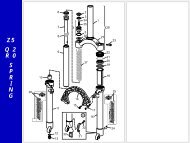
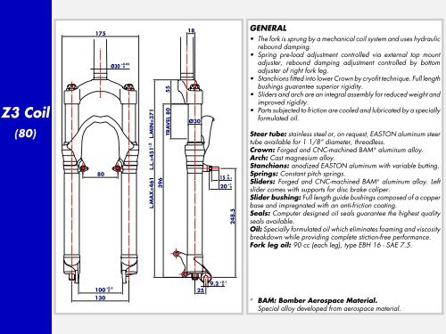
<strong>Z3</strong> Coil(100)17580Ø30 +0.050L.MAX=481 L.L.=471 L.MIN=371±2±2416TRAVEL 100 5518Ø3<strong>01</strong>5200-0.1+10248.5GENERAL• The fork is sprung by a mechanical coil system and uses hydraulicrebound damping.• Spring pre-load adjustment controlled via external top mountadjuster, rebound damping adjustment controlled by bottomadjuster of right fork leg.• Stanchions fitted into lower Crown by cryofit technique. Full lengthbushings guarantee superior rigidity.• Sliders and arch are an integral assembly for reduced weight andimproved rigidity.• Parts subjected to friction are cooled and lubricated by a speciallyformulated oil.Steer tube: stainless steel or, on request, EASTON aluminum steertube available for 1 1/8” diameter, threadless.Crown: Forged and CNC-machined BAM ❊ aluminum alloy.Arch: Cast magnesium alloy.Stanchions: anodized EASTON aluminum with variable butting.Springs: Constant pitch springs.Sliders: Forged and CNC-machined BAM ❊ aluminum alloy. Leftslider comes with supports for disc brake caliper.Slider bushing: Full length guide bushings composed of a copperbase and impregnated with an anti-friction coating.<strong>Seals</strong>: Computer designed oil seals guarantee the highest qualityseals available.Oil: Specially formulated oil which eliminates foaming and viscositybreakdown while providing complete stiction-free performance.<strong>Fork</strong> leg oil: 85 cc (each leg), type EBH 16 - SAE 7.5.10<strong>01</strong>30+0.50259.2 +0.10❊BAM: Bomber Aerospace Material.Special alloy developed from aerospace material.
<strong>Z3</strong> Coil(130)175 1880Ø30 +0.050L.MAX=511 L.L.=5<strong>01</strong> L.MIN=371±2446±255TRAVEL 130Ø3<strong>01</strong>5200-0.1+10248.5GENERAL• The fork is sprung by a mechanical coil system and uses hydraulicrebound damping.• Spring pre-load adjustment controlled via external top mountadjuster, rebound damping adjustment controlled by bottomadjuster of right fork leg.• Stanchions fitted into lower Crown by cryofit technique. Full lengthbushings guarantee superior rigidity.• Sliders and arch are an integral assembly for reduced weight andimproved rigidity.• Parts subjected to friction are cooled and lubricated by a speciallyformulated oil.Steer tube: stainless steel or, on request, EASTON aluminum steertube available for 1 1/8” diameter, threadless.Crown: Forged and CNC-machined BAM ❊ aluminum alloy.Arch: Cast magnesium alloy.Stanchions: anodized EASTON aluminum with variable butting.Springs: Constant pitch springs.Sliders: Forged and CNC-machined BAM ❊ aluminum alloy. Leftslider comes with supports for disc brake caliper.Slider bushing: Full length guide bushings composed of a copperbase and impregnated with an anti-friction coating.<strong>Seals</strong>: Computer designed oil seals guarantee the highest qualityseals available.Oil: Specially formulated oil which eliminates foaming and viscositybreakdown while providing complete stiction-free performance.<strong>Fork</strong> leg oil: 90 cc (each leg), type EBH 16 - SAE 7.5.10<strong>01</strong>30+0.50259.2 +0.10❊BAM: Bomber Aerospace Material.Special alloy developed from aerospace material.
INSTRUCTIONS<strong>Z3</strong> CoilGENERAL RULES1. Where specified, assemble and disassemblethe shock absorption systemusing the MARZOCCHI special tools only.2. On reassembling the suspension system,always use new seals.3. Clean all metal parts with a special,preferably biodegradable solvent, suchas trichloroethane or trichloroethylene.4. Before reassembling, lubricate all partsin contact with each other using siliconefat spray or a specific oil for seals.5. Always grease the lip seal rings beforereassembling.6. Use wrenches with metric size only.Wrenches with inch size might damagethe fastening devices even whentheir size is similar to that of the wrenchesin metric size.
FAILURES, CAUSES AND REMEDIESThis paragraph reports some failures that may occur when using the fork. It also indicates possible causes and suggests a remedy. Alwaysrefer to this table before doing any repair work.FAILURES CAUSES REMEDIES<strong>Z3</strong> CoilOil leaking though the top of slider1. Oil seal is worn out2. Stanchion tube is scored3. Excessive dirt on oil seal1. Replace oil seal2. Replace crown/stanchions assembly,oil seals and dust seals3. Clean the oil seal seat and replace oil sealOil leaking through the bottom of sliderO-rings at pumping element bottom andadjusting rod damaged.Replace the O-rings<strong>Fork</strong> has not been used for some time andis locked outOil seals and dust seals tend to stick tostanchionsRaise dust seal and lubricate stanchiontube, dust seal and oil sealExcessive play of stanchions in the sliders Pilot bushings are worn Replace pilot bushingsAdjuster position does not affect fork operation1. Dirt inside legs2. O-ring into pumping element damaged.1. Clean carefully and change oil2. Replace O-ring.
<strong>Z3</strong> CoilRECOMMENDATIONS FORMAINTENANCEMARZOCCHI forks are based on advancedtechnology, supported by year-long experiencein the field of professional mountainbiking. In order to achieve best results,we recommend to check and cleanthe area below the dust seal and thestanchion tube after each use and lubricatewith silicone oil.In general, MARZOCCHI forks can offer topperformance from the start. However, insome cases a short running-in period isrequired (5-10 hours) for inner adjustments.This running-in period will makefork life longer and ensure fork top performanceover time.IMPORTANT: change oil at least every100 working hours.Polished forks should be cleaned withbodywork polish at regular intervals inorder to preserve their original finish.INSTALLATIONInstalling the fork on a bicycle is a verydelicate operation that should be carriedout with extreme care. The installationshould always be checked by one of ourTechnical Service Centers.WARNING: Steer tube/headsetmounting and adjustment must becarried out in compliance with the headsetmanufacturer’s instructions. Improperinstallation may jeopardize the safety ofthe rider.To replace it, contact one of our TechnicalService Centers with the required tools.WARNING: In case of improperinstallation of the steer tube into thecrown, the rider might lose control of his/her bicycle, thus jeopardizing his/hersafety.DISC BRAKE SYSTEM ASSEMBLYWARNING: If a disc brake systemis installed, it is absolutely forbiddento loosen and remove originalbrake supports fixing pins. In fact, apartfrom retaining Cantilever or V-brake levers,they also play an important role insecuring slider bottom to slider-arch monolith.If needed, replace these pins withscrews (part no. 532979QF) availableas spare parts.Tighten the above screws to 15 Nm.IMPORTANT: screw and pin threadingis treated to ensure hydraulic seal. Neverreuse screws and pins which have beenremoved.Assembling the brake caliper onto theslider is a very delicate operation thatshould be carried out with extreme care.Improper assembly might overstress thecaliper supports which might break.When installing the disc brake system, besure to properly follow the instructionsgiven by the manufacturer.
<strong>Z3</strong> CoilADJUSTMENTSPRING PRELOADSpring preload determines COMPRES-SION damping and is adjusted by turningthe adjustment knob (3) on the top of thefork legs. From the factory the fork is set atminimum preload, i.e. the adjustment knobcompletely unscrewed counterclockwise.However, springs are slightly preloadedto counteract static loads. By turning theadjustment knob clockwise, the preload isincreased up to the maximum value equalto 15 mm spring preload. This adjustmentis essential in order to have the right forkresponse for the rider’s weight and ridingstyle.REBOUND ADJUSTMENTEach fork leg is equipped with an adjusterscrew (C) for REBOUND damping atslider bottom.To adjust, always start from the minimumdamping setting, i.e. with the screw fullyturned counterclockwise. Each adjustingposition can be identified by a click.IMPORTANT: do not force the adjusterknob (C) over its limit.3C
DISASSEMBLYGENERAL– The reference numbers given in this section relate to the components shown in the fork exploded view.– Before starting any operation. please read the diagram below. It shows the quickest procedure and the exact disassemblingsequence. Locate the part you need to remove in the diagram, then look at the arrows to determine which other parts you need toremove first.DISASSEMBLY DIAGRAM<strong>Z3</strong> CoilSPRING CHANGE▲STANCHION TUBE CAP FIG. 1▲SPRING FIG. 2▲FORK LEG OIL CHANGE▲PILOT BUSHING ANDSEAL ASSEMBLY CHANGE▲BOTTOM ADJUSTER FIG. 3▲FOOT NUT FIG. 4▲CROWN AND STANCHIONSASSEMBLY FIG. 5▲DUST SEAL FIG. 6▲STOP RING. 7▲OIL SEAL FIG. 8▲CHANGING PUMPINGELEMENT SEALS▲FOOT BUFFER FIG. 11▲PUMPING ROD FIG. 12▲REBOUND SPRING FIG. 12▲PUMPING ELEMENT INNER O-RINGFIG. 13▲VALVE ASSEMBLYCHANGE▲UPPER WASHER FIG. 9▲STOP RING FIG. 14▲ ▲PILOT BUSHING FIG. 10 VALVE ASSEMBLY FIG. 14
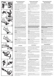
SPRING CHANGEFIG. 1Unscrew the caps (4) with a 21 mmsocket wrench.Remove the caps complete with O-ring(5) from the stanchions.FIG. 2Push the stanchions into the sliders andremove the lower washer (11) and thespring (34) from each fork leg.Drain all oil from the fork legs.WARNING: Remember to alwaysrecycle any used oil.PILOT BUSHING AND SEALASSEMBLY CHANGEFIG. 3 (only right leg)Turn fork legs upside down and pressadjuster retainer (28) with a small screwdriverto release it. Remove adjuster assembly(28) from the slider.<strong>Z3</strong> CoilTo change the fork leg oil follow theprocedure as described in section“REASSEMBLY” from Fig. 27 to Fig. 29.34114528
FIG. 4Remove foot nuts (26) and (29) with asocket wrench.FIG. 5Withdraw the crown and stanchions assembly(1) from the sliders.FIG. 6Remove the dust seal (19) from the top ofthe sliders using a small screwdriver.<strong>Z3</strong> CoilDx.191Sx.2926
FIG. 7Remove the stop ring (20) from the slidersby placing the screwdriver bit in one of thethree openings on the stop ring.IMPORTANT: when removing the stopring, make sure not to damage its seat.FIG. 8Fit the slider protector (A) onto the sliderand remove the oil seal (21) with the helpof a large screwdriver.IMPORTANT: when removing the oilseal, make sure not to damage its seat.Once removed the oil seals should not beused again.FIG. 9Remove the upper washer (22) from theslider.<strong>Z3</strong> Coil2021A22
FIG. 10Fit the bit of a small screwdriver into upperedge slot of the pilot bushing (23) and liftgently. Pull the bushing out of the sliderand make all necessary changes.REPLACING PUMPING ELEMENTSEALSFIG. 11Remove the foot buffer (18) completewith ring (25) from the pumping rod ends(14) and (12).FIG. 12Withdraw the pumping elements (14)and (12) and the rebound spring (15)from the stanchion tube top. Replace theseal ring (13) if damaged or worn out.<strong>Z3</strong> Coil2325 18 12Sx.Dx.131525 18 1414 12
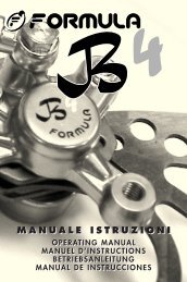
<strong>Z3</strong> CoilFIG. 13 (only right leg)Remove the stop ring (33) from pumpingelement bottom (14) with a small flatscrewdriver.Mark stop ring seat into inner rod forproper fitting.Use the same screwdriver to remove thering (A) and screw inner rod until adjusterthreaded end is disengaged from pumpingelement.Remove inner rod and replace O-ring(27) if damaged.VALVE ASSEMBLY CHANGEFIG. 14To check that the valve assembly is operatingcorrectly, it is necessary to work onthe inside of the stanchion tube.Slip off the stop ring (17) using pointedpliers.Pull the valve assembly (16) out of thetube with one finger in the same sequenceas in the figure.33141727A16
<strong>Z3</strong> CoilREASSEMBLYCAUTION: before reassembling, all metalcomponents should be washed carefullywith inflammable, preferably biodegradable,solvent and dried with compressedair.PILOT BUSHING AND SEALASSEMBLYFIG. 15Check that no dirt or debris is betweenslider and bushing. Insert the pilot bushing(23) into place so that it adheres to theslider.FIG. 16Fit the upper washer (22) into the slider sothat it touches the pilot bushing.FIG. 17Lubricate the oil seal (21) and place itonto the seal press (B) with the hollowside toward the slider.Press the oil seal until it touches the lowerwasher by using the above seal press.2322B21
FIG. 18Insert the stop ring (20) into the slidermaking sure it is properly seated intoplace.Use buffer (B) to properly seat the ringinto the slider.FIG. 19Lubricate the dust seals (19) and fit theminto the stanchions from the spring end.PUMPING ROD ASSEMBLYFIG. 20 (only right leg)Lubricate the O-ring (27) and fit inner rodthreaded end into pumping element (14).Turn inner rod clockwise so that threadedend can be seen the into pumping elementand stop ring seat (33), marked duringdisassembly.Fit stop ring (33) into inner rod seat andring (A) into pumping element seat.<strong>Z3</strong> Coil2<strong>01</strong>927A3314
VALVE AND PUMPING RODASSEMBLYFIG. 21After having overhauled or replaced thevalve unit and after having cleaned theinside of the tube, reassemble. Assemblevalve components (16), in correct sequence.Then fit pumping elements (12) and (14)with seal ring (13) and rebound spring(15) into the valve assembly (16).FIG. 22Lubricate the O-rings (24-25) and reassemblethe foot buffer (18) onto pumpingelement ends (14) and (12).FIG. 23Fit this assembly into the stanchion tubeand properly seat the valve assembly(16).Insert the stop ring (17).<strong>Z3</strong> Coil2524Dx.12-1416151318 1425 24Sx.1618 1217
<strong>Z3</strong> CoilCROWN AND STANCHIONSASSEMBLYFIG. 24Fit the crown and stanchions assembly (1)- with the dust seals in place - gently intothe sliders seals.IMPORTANT: to avoid any damages tosealing surfaces, keep the stanchions dulylubricated and squared into the sliders.Press the crown and stanchions assemblyfully down and check that threaded ends ofpumping elements (14) and (12) are comingout through the bottom of the sliders.Check to see that the stanchions slideunrestricted by cycling the fork up anddown several times.The tube should slide freely inside the sealassembly without any side play. In the eventit is too hard or too soft, repeat the previoussteps described above and check componentsto ensure they are not damaged.Seat the dust seals (19) on top of thesliders.FIG. 25Screw the foot nuts (26) and (29) on thethreaded elements of pumping elements(14) and (12).Tighten to 12 Nm.Check to verify that the stanchions slideproperly through the stroke by pumpingthem up and down several times.FIG. 26Fit the retainer (D) into the slider (E) toreassemly the adjuster unit (28).12NmDx.1Sx.19 19 292628 D E
HOW TO FILL WITH OILFIG. 27Pour oil little by little when the stanchionsare fully down and then pump with thecrown so as to have a better filling.Ensure proper oil level (H), from the top ofthe stanchion tube, in both legs.SPRING AND CAPFIG. 28Fit the springs (34) into each stanchiontube.FIG. 29Lubricate the O-ring (5) on the cap (4).Turn the preload adjuster (9)counterclockwise until it is at its minimumsetting and install the lower washer (11).Start the caps with the O-ring (5) in placeinto the stanchion tube threads by hand.Tighten caps (4) to 12 Nm.<strong>Z3</strong> Coil3412NmHTravel (mm) H (mm)80 35100 40 Lh.35 Rh.130 5045
SPECIFIC MARZOCCHI TOOLSRef. Item. Description and useA R 5089 AB Slider protector: to remove the oil seal from the sliderB R 5090 Oil seal press: to press oil seal into the slider<strong>Z3</strong> CoilBA