General Catalogue 2007 - Ibemo Kazakhstan Ltd
General Catalogue 2007 - Ibemo Kazakhstan Ltd
General Catalogue 2007 - Ibemo Kazakhstan Ltd

Create successful ePaper yourself
Turn your PDF publications into a flip-book with our unique Google optimized e-Paper software.
Breaking Capacity<br />
An attempt has been made to try and make the assigned shortcircuit<br />
breaking capacities of a circuit breaker more understandable<br />
to the specifier and of more practical use to the designer than the old<br />
P1 and P2 ratings. The British Standard still specifies two ratings<br />
I cu : Rated ultimate short-circuit breaking capacity<br />
I cs : Rated service short-circuit breaking capacity.<br />
Ultimate Short Circuit Breaking Capacity<br />
Icu corresponds in practice to P1 in the former standard and is<br />
defined in the same way. This is now covered under test sequence 3,<br />
which is:<br />
• Verify the overcurrent releases at 2.Ir;<br />
• Two successive breaks at Icu,<br />
cycle 0 - 3 min - CO;<br />
• Dielectric withstand at 2Ue (50Hz, 1 min);<br />
• Verify the calibration of the over-current releases.<br />
I cu Represents the maximum short-circuit current which the breaker<br />
can break and is to be compared with the prospective fault<br />
current at the point of installation:<br />
I cu (Of the device) Must be equal to or greater than the prospective<br />
short-circuit at the point of installation.<br />
Service Short-circuit Breaking Capacity<br />
<strong>General</strong>ly, when a short-circuit occurs (in itself a very rare<br />
occurrence) its value is much lower than its calculated value.<br />
Nonetheless, it is essential that these lower values of short- circuit<br />
are cleared effectively and safely, and that the supply is re-established<br />
as quickly as possible. It is for this reason that BS EN 60947-2<br />
has introduced a new characteristic. I cs known as Service Breaking<br />
Capacity and generally expressed as a percentage of I cu . The value<br />
can be chosen by the manufacturer from 25, 50, 75 or 100%.<br />
I cu must be verified as described under test sequence 2 which is:<br />
• Three successive breaks at Ics with<br />
cycle 0 - 3 min - CO - 3 min - CO;<br />
• Dielectric withstand at 2Ui (50 Hz, 1 min);<br />
• Temperature rise at In;<br />
• Verify the calibration of the over-current releases.<br />
This establishes I cs as a performance characteristic which can be<br />
considered not simply as a breaking capacity (as was the case of P2)<br />
but as the ability of the circuit breaker to ensure normal service, even<br />
after having disconnected several short-circuits.<br />
The percentage ratio of I cs to I cu is another important aspect for the<br />
designer to understand. Our wiring regulations, which are based on<br />
IEC 364, give no guidance at the moment on the use of performance<br />
characteristic Ics. To comply with these regulations it is only<br />
necessary for the ultimate breaking capacity of the protective device<br />
to be equal to or greater than prospective fault level: I cu ≥ I cs .<br />
The selection of the percentage ratio of I cs to I cu to achieve optimum<br />
continuity of service depends on the “probable short circuit level”.<br />
Therefore Ics should be equal to or greater than the probable short<br />
circuit level. However for large air circuit breakers it is usual for<br />
I cs = I cu , i.e. 100% because these devices are usually installed as main<br />
incomers to large switchboards where their field of protection is often<br />
limited to the switchboard itself. In these conditions the probable I cs<br />
will be only slightly less in comparison with the I cu .<br />
It is important for this application to select a device where<br />
I cs performance is close to I cu .<br />
Hager <strong>Catalogue</strong> <strong>2007</strong> • Technical<br />
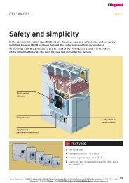
MCCB Breaking Capacity &<br />
Temperature Derating<br />
While this holds true for large switchboards, designed for high<br />
prospective fault levels, it is possible to use lower rated circuit<br />
breakers as incomers on panelboards designed for a relatively low<br />
prospective fault level. This provided that the service performance<br />
level is equal to or greater than the prospective fault level.<br />
For example, it is possible to install an H630 moulded case circuit<br />
breaker as a main incomer on a switchboard supplied from a 400kVA<br />
transformer because the H630 Ics is greater than the PSCC.<br />
However, for those circuit breakers which are usually installed as<br />
outgoers, protecting cables to sub-boards or other loads, a 50% ratio<br />
is adequate because studies have shown that when a short-circuit<br />
does occur it is nearly always single or two phase and located at<br />
the extremity of the protected cable, and is usually less than 25% of<br />
the prospective fault level at the origin of the system and, in almost<br />
all cases, not greater than 50%. It is therefore a wise precaution, to<br />
prolong the working life of the installation, to choose a device having<br />
a service performance Ics equal to 50% Icu. It is advisable to base<br />
the Ics rating of a MCCB on the pscc at the extremity of the circuit<br />
that it is protecting.<br />
Temperature Derating<br />
Hager MCCBs are designed and calibrated to carry their rated<br />
current and to operate within this designated thermal time/current<br />
zone at 40 o C. If the ambient temperature around the circuit breaker<br />
differs from 40 o C then it requires more or less current to operate the<br />
thermal trip depending on the ambient temperature variation.<br />
Table 24 shows the variation of the range of the thermal trip as a<br />
function of the ambient temperature. The instantaneous magnetic trip<br />
is not affected by variations in ambient temperature.<br />
Variation of Thermal Trip Range with Ambient Temperature<br />
30ºC 40ºC 50ºC 60ºC<br />
Type In min max min max min max min max<br />
125A 16 - 16.0 - 16.0 - 15.4 - 14.0<br />
20 - 20.0 - 20.0 - 19.2 - 18.0<br />
25 - 25.0 - 25.0 - 24.0 - 25.5<br />
32 - 32.0 - 32.0 - 30.7 - 28.8<br />
40 - 40.0 - 40.0 - 38.4 - 36.0<br />
50 - 50.0 - 50.0 - 48.0 - 45.0<br />
63 - 63.0 - 63.0 - 60.5 - 56.7<br />
80 - 80.0 - 80.0 - 76.8 - 72.0<br />
100 - 100.0 - 100.0 - 96.0 - 90.0<br />
125 - 125.0 - 125.0 - 120.0 - 112.5<br />
250A 160 128.0 160.0 128.0 160.0 122.9 153.6 115.2 144.0<br />
200 160.0 200.0 160.0 200.0 153.6 192.0 144.0 180.0<br />
250 200.0 250.0 200.0 250.0 192.0 240.0 180.0 225.0<br />
400A 320 256.0 320.0 256.0 320.0 245.8 307.2 230.4 288.0<br />
400 320.0 400.0 320.0 400.0 307.2 384.0 288.0 360.0<br />
630A 500 400.0 500.0 400.0 500.0 384.0 480.0 360.0 450.0<br />
630 504.0 630.0 504.0 630.0 483.8 604.8 453.6 567.0<br />
800A 800 640.0 800.0 640.0 800.0 614.4 768.0 576.0 720.0<br />
Table 24<br />
ibemo <strong>Kazakhstan</strong> - 090301 Republic of <strong>Kazakhstan</strong>, West <strong>Kazakhstan</strong> Oblast, Aksai, Pramzone, BKKS office complex<br />
Phone: +7 71133 93077 ; Fax: +7 71133 93074 ; E-Mail: info@ibemo-kz.com<br />
3.41<br />
Protection<br />
Devices