WBAN 82-302 - Delta-Temp
WBAN 82-302 - Delta-Temp
WBAN 82-302 - Delta-Temp

You also want an ePaper? Increase the reach of your titles
YUMPU automatically turns print PDFs into web optimized ePapers that Google loves.
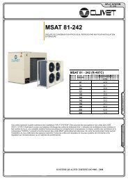
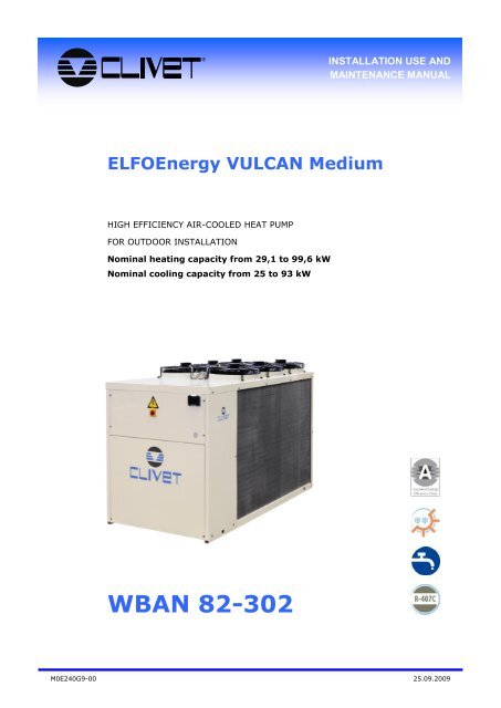
®INSTALLATION USE ANDMAINTENANCE MANUALELFOEnergy VULCAN MediumHIGH EFFICIENCY AIR-COOLED HEAT PUMPFOR OUTDOOR INSTALLATIONNominal heating capacity from 29,1 to 99,6 kWNominal cooling capacity from 25 to 93 kW<strong>WBAN</strong> <strong>82</strong>-<strong>302</strong>M0E240G9-00 25.09.2009
Dear Customer,We congratulate you on choosing an ELFOSystemproduct, the air conditioning system at annual cyclethat offers the possibility in a sole system of meetingall the heating, conditioning and domestic hot waterneeds.Clivet is being working for years to offer systems ableto assure the maximum comfort for long time withhigh reliability, efficiency , quality and safety. Thetarget of the company is to offer advanced systems,that assure the best comfort, reduce the energy consumption,the installation and maintenance costs forall the life-cycle of the system.With this manual, we want to give you informationthat are useful in all the phases: from the reception,to the installation and use until the disposal so that asystem so advanced offers the best procedure of installationand use.Best regards and have a nice reading !CLIVET SpaThe data contained in this bulletin is not binding and may be changed by the manufacturer without prior notice. All reproduction,even partial, is PROHIBITED
GENERAL1 MANUALProvides correct unit installation,use and maintenanceIt is advisable to read it carefullyso you will save timeduring operationsFollow the written indicationsso you will not causedamages to things and injuriespeopleKeep with the wiring diagramin a accessible placefor the operator2 QUALIFIED PERSONALonly qualified personnel canintervene on the unit, asrequired by the regulationsin force.Install ati o n , s tart i ng ,maintenance and repairrequired specific knowledge;if they are carried out byinexperienced personnel,they may cause damages tothings and injuries people.3 RISK SITUATIONSThe unit has been designedand created to preventinjures to peopleDuring designing it is notpossible to plane andoperate on all risk situationRead carefully RESIDUALRISK section where allsituation which may causedamages to things andinjuries to people arereported.4 INTENDED USEUse the unit for the intendeduse only:cooling/heating water or awater and glycol mix for airconditioning,within limitsdefined in the technicalbulletin and on this manual.Any use other than intendeddoes not involve themanufacturer in anycommitment or obligation5 INSTALLATIONF o l l o w l o c a l s a f e t yregulationsKeep out of children’s reachthe packing material becauseis a potential danger sourceVerify that the electrical linecharacteristics are incompliance with data quoteson the unit serial numberlabelKeep packing material out ofchildren’s reach it may bedangerousRecycle and dispose ofp a c k i n g m a t e r i a l s i ncompliance with localregulations.6 PERIODIC INSPECTIONSC a r r y o u t p e r i o d i cinspections to check allreleased, deteriorated or outof order partsCarrying out periodicschecks avoids or minimizesrepairing costs.8 MODIFICATIONAll unit modifications willend the warranty coverageand the manufacturerresponsibility.9 BREAKDOWNMALFUNCTIONDisable the unit immediatelyin case of breakdown ormalfunctionContact a constructorcertified assistance serviceUse original spares partsonlyUsing the unit in case ofbreakdown or malfunctionmay damage the machinesafety and increase costsand time.10 USER TRAININGThe installer has to train theuser on :start-up / shutdownset points changestandby modemaintenancewhat to do / what not to doin case of breakdown11 DATA UPDATEC o n t i n u a l p r o d u c timprovements may implymanual data changesVisit manufacturerweb sitefor updated data7 MAINTENANCETurn the machine off beforeany operationOperating in compliance withlocal safety regulationsM0E240G9-00 Page 4 25/09/2009
UNIT IDENTIFICATIONSERIAL NUMBER LABELThe serial number label allows you to indentify all machinefeatures and it has not to be removed for any reason .The label is placed on the unit, generally beside the electricalpanel and also on the external panelling.It reports the regulations indications such as:Machine type (series and size)serial numberyear of manufacturewiring diagram numberelectrical datamanufacturer logo and addressSERIAL NUMBERIt identifies uniquely each machine.It identifies specific spare parts for the machineASSISTANCE REQUESTSIn case of intervention you have to provide data indicatedbelow.Note data from the serial number label and write them in thechat below, so you will find them easily when needed.SERIESIZESERIAL NUMBERYEAR OF MANUFAC-WIRING DIAGRAMM0E240G9-00 Page 5 25/09/2009
RECEPTION1 RECEPTION CHECKINGBefore accepting the deliveryyou have to check:that the unit hasn’t beendamaged during transport.that the delivered materialmatches the description onthe transport documentIn case of damage oranomaly :Write down on the transportdocument the damage youfound and quote thissentence:CONDITIONAL ACCEPTANCE —CLEAR EVIDENCE OFDEFICIENCIES/DAMAGESDURING TRANSPORTContact supplier and thecarrier by fax and registeredmail with advice of receipt.Contestations should bedone within 8 days fromreception.Signalling over this periodaren’t valid.2 STORAGEObserve external packinginstructionsKeep the unit in a dry placeDo not putting other objectson the unit (except withins u p e r i m p o s i t i o n l i m i t sindicated on packing)Do not place unit thermoretractable protection underthe sun as circuit pressuremay raise until activatingsafety valves4 PACKING REMOVING3 HANDLINGBefore handling :Operate in compliance withsafety regulations in forceVerify unit weight andhandling equipment liftingcapacityidentify critical points duringhandlingdisconnected routesflights / stepsdoorsConsiderer that thebarycentre could out ofcentreverify that the unit keeps itsbalanceUse single protection devices : gloves, glasses ecc.Remove the packaging: be careful not to damage the unit.Verify unit integrityRecycle and dispose of packing material in conformity with localregulations.Sizes <strong>82</strong> 122 162 202 262 <strong>302</strong>Shipping weightKg430 474 647 681 814 834M0E240G9-00 Page 6 25/09/2009
20O P700 (14)700 (15)1050700 (14)O PO P20700 (15)700 (14)147414741474POSITIONING23 POSITIONING3 3 3 33333 3 3 33 333713 131 GENERALDuring positioning consider theseelements :technical spaces required forthe machine and systemplace where the machine willbe installedelectrical connectionswater connectionsair / aeraulic ductsDo not considerer these elementscould decrease performances andoperational life of the unit.2 FUNCTIONAL SPACESFunctional spaces are designedto:guarantee good unitoperationCarry out maintenanceoperations3 3310p r o t e c t a u t h o r i z e doperators and exposed2people 1012 116 Respect all functional spaces754indicated 1 in DIMENSIONSsection .8Double all functional spaces iftwo or more unit are aligned6513 9 13 913241 1 11846 13 241W123289 13241 20 13 1050 13 201100W2 700 (14)13 13 700 (15)W1Units are designed to beinstalled:OUTDOORSin fixed positionsHow to limit vibrationtransmission :use antivibration devices onunit bearing/supportingpointsinstall flexible joints on thehydraulic/ aeraulic/coolingconnectionsInstallation standards :Safe accessible positionavoid flood-prone placesverify unit weight andbearing point capacityverify that all bearing pointsare aligned and leveledinstall the unit raised fromthe ground81010consider the maximum snow1211level11 4113 1320 13 1050 9 20913241 2446 2411100293227A correct air circulation isindispensable to ensure thegood machine operation;so please avoid :Air flow obstaclesdifficulty in circulationleaves or other objects thatmay block the exchangercoilswinds that contrast orassist the air flowheat or pollutants sourcesnear the unit (flue pipe,extractors ecc)stratification (cold air thatstagnate at the bottom)recirculation (exhaust airthat is retake in suction)positioning under theground level, near veryhigh walls , under roof or inangles that can createstratification or recycling10phenomenon1 120 13 1050 13 2011001211Negleting the previousindications can cause :13 13W2LOW PRESSURE (in winter)8Worsening of energyefficiencyworking anomaliesstops due to HIGHPRESSURE (in summer) or13W21411"G"FUNCTIONAL SPACES14"G"700 (14)Sizes <strong>82</strong>-122 Sizes 162-202 Sizes 262-<strong>302</strong>W313 13W4W313 13W4 700 (15)13W4 700 (15)MNMNN700700700700110070019287001100700232870011007002932M0E240G9-00 Page 7 25/09/2009
WATER CONNECTIONS - 11 GENERALSelection and installation ofsystem components must becarry out by installer.Following you will find someindications to integrate with whatis provided by the localregulations in force and by thegood technical laws2 COMPONENTSINTERCEPTING VALVESInstalled at entry and exit allowmaintenance operations withouthaving to empty the system.THERMOMETERS AND MANOME-TERSInstalled at entry and exit of themain elements facilitate inspectionand maintenance.ESCAPE VALVESInstall all the system highestpoints in order to permit the circuitair venting.BLEEDING COCKInstalled in the system low pointsthey allow the discharge.EXPANSION TANKIt keeps a correct system pressurewhen the water temperaturechanges.It must be dimensioned as afunction of water content.Could be necessary install in additionon the unit one or more of itFLOW SWITCHObligatory if it is not present inthe unit .FILTERIt is obligatory if it is not presentin the unit .The filter never should be removed,this operation invalidatesthe guarantySUPPORTSThe hydraulic pipes weight mustn’tburden on the unit connections3 OPERATIONS SEQUENCESYSTEM WASHINGBefore connecting the unit,carefully wash the system byfilling it and emptying it severaltimes with clean water.Ignoring this operation willlead to several filter cleaninginterventions and at worstcases can cause to damageto the exchangers and theother parts.LEAKAGE TESTExecute leakage test beforeisolate the pipes.PIPES INSOLATIONTo avoid heat dispersions andformation of condensate isolateall the pipes.Leave various point of servicefree (wells, vent-holes etc )4 WATER QUALITYWater quality is determined bythe following factors:INORGANIC SALTSpHBIOLOGICAL LOAD(seaweeds etc)SUSPENDED SOLIDSDISSOLVED OXYGENIt is important that qualifiedpersonnel check the waterqualityWater with inadequate characteristicscan cause:pressure drop increaseenergy efficiency decreasecorrosive symptom increase5 RISK OF FREEZEIf the unit or the relativewater connections can besubject to temperatures closeto 0°C adopt measures forprevent risk of freeze.For example:Mix water with ethyleneglycolSafeguard the pipes withheating cables places underthe insulationEmpty the system verifyingthat:- don’t remain close cocksthat can trap water evenafter emptying- there aren’t low pointswhere water can stagnateeven after emptying; ifnecessary make a blowing6 ANTI-FREEZESOLUTIONConsider that the use of antifreezesolution determines anincrease in a pressure drop.Make sure that the glycol typeutilized is inhibited (notcorrosive) and compatiblewith the hydraulic circuitcomponents (pump etc).M0E240G9-00 Page 8 25/09/2009
ELECTRICAL CONNECTIONS - 11 GENERALELECTRICAL LINESThe characteristics of the electricallines must be determined byspecialized personnel able to designelectrical installations; moreover,the lines must be in conformitywith regulations in force.PROTECTION DEVICESThe protection devices of the unitpower line must be able to stop ofpresumed short circuit current,whose value must be determinedin function of system characteristicCABLES SECTIONThe power cables and the protectioncable section must be definein accordance with the characteristicsof the protections adoptee.ELECTRICAL DATAThe serial number label reportsthe unit specific electrical data,included any electrical accessories.The electrical data indicated inthe technical bulletin and in themanual refer to the standard unit,accessories excluded.Refer to the electrical data reporton the serial number label.serial number label2 CONNECTIONS1. All electrical operationsshould be performed by trainedpersonnel having thenecessary requisites by theregulations in force andbeing informed about therisks relevant to these activities.2. refer to the unit electricaldiagram (the number of thediagram is shown on theserial number label)3. verify that the network hascharacteristics conformingto the data shown on theserial number label4. make sure that the unitsupply line is selected atstart.5. Shelter the cables usingadequate measure fairleads6. Before starting work, verifythat the sectioning device atthe start of the unit powerline is open, blocked andequipped with cartel warning7. Primarily you have to realizethe earthing connection8. Before power the unit, makesure that all the protectionsthat were removed duringthe electrical connectionwork have been restored.3 SIGNALS / DATA LINESDo not overpass themaximum power allowed,which varies, according tothe type of signal.Lay the cables far frompower cables or cableshaving a different tensionand that are able to emitelectromagneticdisturbances.Do not lay the cable neardevices which can generateelectromagneticinterferences.Do not lay the cablesparallel to other cables;cable crossings arepossible, only if laid at 90°.Connect the screen to theground, only if there aren’tdisturbancesGuarantee the continuity ofthe screen during theentire extension of thecable.Respect impendency,capacity and attenuationindications.TENSIONEVOLTAGE / SPANNUNGTENSIONV / Ph / HzF.L.A. A F.L.I. kWSCHEMA ELETTRICOWIRING DIAGRAM / SCHALTPLAN N°SCHEMA ELECTRIQUE / ESQUEMA ELECTRICOF.L.A. full load ampereFull load current at max admissible conditionsF.L.I. Full load inputFull load power input( at max. admissible condition )M0E240G9-00 Page 9 25/09/2009
ELECTRICAL CONNECTIONS - 2unit ELECTRICAL PANEL 400/3/50 +NQS1AP1AP4AP4A/BAP5AP9AP10/11FU1FU2FU3FU4FU6 – FU7FU8-FU9-FU10KA1…KA5KM1 - KM2KM3KM5QM1 - QM2QM3QS1T1T2XS1XS2XS3XS4Main control moduleBase for interfaceFan control moduleRS 485 modulePhase monitor moduleSoft starterFuse of the control circuitFuse of the phase monitorFuse of the phase monitorFuse of the control circuitFan fuseHeater fuseAux relayCompressor contactorContactor of the pump utility sideHeater contactorCompressor sentinel breakerSentinel breaker of the pump utility sideMain isolator switchAux. circuit transformerAux. circuit transformerTerminal block of the power supplyTerminal block of the power supplyTerminal block for the connection of the remote condensino unitTerminal block for supervisor connectionM0E240G9-00 Page 10 25/09/2009
ELECTRICAL CONNECTIONS - 3The configuration parameters are indicated in the START-UP sectionXC5 terminal block of Customer connectionson AP1 main control moduleXC5REMOTE ON OFFSA1XC53940Summer—WinterSA2XC52122Second SETPOINTSA3XC534DHW requestSA4XC54142CAPACITY limitationSA5XC578UTILITY flow switchSQ2XC556Water resetDemand limitExt. HUMIDITY probeSignal 4...20mAXC529304-20 mA+XC59100..10 V0 VXC51112H15 VSignal 0...10VXC50..10V47480VSignalling of compressoroperating - optionmax 24 VKM1 – KM2 1 A5354Electrical panel : KM1 - 2KM1-2M0E240G9-00 Page 11 25/09/2009
ELECTRICAL CONNECTIONS - 4The configuration parameters are indicated in the START-UP sectionterminal block of Customer connectionson AP1 main control moduleXC1XC2XC5Distribution pump - supplied by theCustomer3-way valve - supplied by the CustomerControlThermal protectionXC1112KMPUmax 230V ACmax 16A AC1XC5FRPU2526ControlXC53940DHW controlXC2546max 230V ACmax 1A AC1DHW requestXC54142Heater in REPLACEMENTHeater in INTEGRATION<strong>WBAN</strong>XC5XC251522131011max 230V ACmax 1A AC1YVBYVBYVABT9XC5XC13334167KM4ST9BT14YVAM0E240G9-00 Page 12 25/09/2009
ELECTRICAL CONNECTIONS - 5Remote multifuntional keypadThe keypad can be placed in a remote position for 2 different reasons :1. To directly interface with the unit without moving from the unit installation place2. To be used as room thermostat, that measures the ambient temperature and manages the thermoregulationcontrollino the pump on the secondarySee the CONTROL section.The KEYPAD SUPPORT accessory is necessary.Keypad supportKeypad rear view :2 coils type AA LR6+ +Connection between unit and remote keypad supportMax 1000 mtAP3GND+-2 x 0.25+ shield3 x 1.52 3- +23<strong>82</strong>0M0E240G9-00 Page 13 25/09/2009
ELECTRICAL CONNECTIONS - 6Connection to supervisor / MODBUS netPosition of the terminal block inthe electrical panelXGACouple of conductors twisted and shieldedSection of conductor 0.22mm2…0,35mm2Nominal capacity between conductors < 50 pF/mnominal impedance 120 ΩRecommended cable BELDEN 3105AS +S -GNDS+ S-+-+-GNDM0E240G9-00 Page 14 25/09/2009
START-UP - 11 GENERAL4 HYDRAULIC CIRCUITThe indicated operationsshould be done by qualifiedtechnician with specifictraining on the product.Upon request, the servicecentres performing the startup;the electrical, waterconnections and the othersystem works are by theinstaller.Agree upon in advance thestar-up data with the servicecentreBefore realizing the unitconnection make sure thatthe hydraulic system hasbeen cleaned up and theclearing water has beendrainedCheck that the water circuithas been filled andpressurizedCheck that the shut-offvalves in the circuit are inthe "OPEN" position.Check that there isn’t air inthe circuit, if required,evacuate it using the airbleed valve placed in thesystem high points.When using antifreezesolutions, make sure theglycol percentage is suitablefor the type of useenvisaged.2 PRELIMINARY CHECKSBefore checking, please verifythe following :the unit should be installedproperly and in conformitywith this manual.the electrical power supplyline should be sectioned atthe beginning.The line sectionalizingdevice is open, locked andequipped with the suitablewarningmake sure no tension ispresent3 REFRIGERANT CIRCUITCheck carefully therefrigerating circuit: thepresence of oil stains canmean leakage caused bytransportation, movementsor other).Open the cocks of therefrigerator circuit, if thereare any.verify that the refrigeratingcircuit is in pressure: Usingthe unit manometers , ifpresent, or servicemanometers.Make sure that all theservice outlets are closedwith proper caps; if capsare not present a leak ofrefrigerant can be possible.Weight of glycol (%) 10 20 30 40Freezing temperature (°C) -4 -9 -15 -23Safety temperature (°C) -2 -7 -13 -21Verify that the unit isconnected to the groundplantCheck the conductorstightening: the vibrationscaused by handling andtransport might causeloosingFeed the unit by closing thesectioning device, but leaveit on OFF.Check the tension and linefrequency values whichmust be within the limits :230/1/50 + / - 6%400/3/50 + / - 6%5 ELECTRICAL CIRCUITCOMPRESSOR CRANKCASE RESISTANCES (se presenti)Feed the oil resistances on the compressor crankcase at least 8 hoursbefore the start compressor :at the first unit start-upafter each prolonged periods of inactivityCheck that the phasesunbalancing is lower than2%Example:L1 - L2 = 388 VL2 - L3 = 379 VL3 - L1 = 377 Vaverage= 381(388+379+377) / 3 = 381maximum deviation = 7 V(388-381) = 7unbalance = 1,83 %(7/381)x100=1,83%ACCEPTABLEThe working out of thelimits can cause irreversibledamages and voids thewarranty1. Feed the resistances closing the unit isolator (sorter??).2. Control the resistances electrical absorption to be sure that they’refunction .3. Carry out start-up only if the compressor crankcase temperature onthe lower side must be higher at least of 10° C than the outsidetemperature.Do not start the compressor with the crankcase oil below operatingtemperature .M0E240G9-00 Page 15 25/09/2009
START-UP - 26 TEST BLANK9 SCROLL COMPRESSORS10 SETPOINTDuring possible test blankcheck that the electronicthermostatic valve (or solenoidvalve) remains closed.Otherwise, the compressormay be damaged for liquidreturn.7 TENSIONSABSORPTIONSCheck that the air and watertemperatures are included inthe working limitsFor information on the controlsystem, refer to the paragraphCONTROL.Start the unitWith unit of full load, namelyin stable conditions and closeto those of work, check :Power supply tensionPhase unbalanceTotal absorption of the unitAbsorption of the singleelectric loads8 REMOTE CONSENTCheck that the remotecommands (ON-OFF, etc.)are connected and ifnecessary enabled with therelevant parameters asdescribed in ELECTRICALCONNECTIONS sectionCheck that probes oroptional components areconnect and enable with ther e l a t i v e p a r a m e t e r s( ELECTRICAL CONNECTIONsection)Verify the unit compressortype on the GENERALTHECNICAL DATA table .The Scroll compressors haveonly one direction of rotation.Make sure the direction ofrotation is correct, measurethe condensation and suctionpressure.Pressure must clearly differ: atthe start, the suction pressuredecreases whilst thecondensation pressureincreases.If the direction of rotationisn’t correct:the compressor becomenoisyafter few minutes thecompressor will stop for theactivation of the thermalprotectionIn this event, cut the powerand reverse the 2 phases onthe machine power.Prevent the compressor fromworking with in reverserotation: more than 2-3anomalous starts up candamage it.The phase optional monitor,which controls the phasesequence, can be installedlater.CE 97/23 PED DIRECTIVECheck, and if it is necessarymodify, the set-pointsshown in the CONTROLsection11 STARTING REPORTRealize the operating objectiveconditions is useful for checkthe unit over time.With unit of full load, namelyin stable conditions and closeto those of work, take thefollowing data:T e n si o n a n d ge n era labsorptions with unit at fullloadAbsorption o f v ari ede l e c t r i c a l l o a d s(compressors, fans, pumpsetc)<strong>Temp</strong>eratures and capacitiesof different liquid (water,air) in the inlet and outlet ofthe unit<strong>Temp</strong>eratures and pressureson the refrigerant circuitc h a r a c t e r i s t i c p o i n t s(compressor discharge,liquid, intake)The remarks should bepreserved and available duringmaintenance .97/23 CE PED DIRECTIVE gives instructions for installers, usersand maintenance technicians as well.Refer to local actuation norms; briefly and as an example, see thefollowing :COMPULSORY VERIFICATION OF THE FIRST INSTALLATIONonly for units assembled on the installer’s building site (for ex.Condensing circuit + direct expansion unit)CERTIFICATION OF SETTING IN SERVICE for all the unitsPERIODICAL VERIFICATIONS to be executed with the frequencyindicated by the Manufacturer (see the MAINTENANCE section)M0E240G9-00 Page 16 25/09/2009
START-UP - 3SET POINT CORRECTION FOR OUTSIDE TEMPERATURESUMMERWith outside low temperatures the refrigerant requirementsare reduced.The internal comfort can also be obtained with a set-pointhigher than standard.The correction is summed to SP set-point :it increases at the outside temperature T.Ex. decreasingWINTERWith outside mild temperatures the thermal requirements arereduced.The internal comfort can also be obtained with a lower setpoint.The correction is subtracted to SP set-point :lo diminuisce all’ aumentare della temperatura esterna T.ExSP116SP117112 113T.Ex115 114T.ExConfiguration parameters4 CompExt External temp. comp. enabling 0=No 1=Cool 2=Heat 3=Always112 CextMaxC Ext. <strong>Temp</strong>. max. winter correction113 CextMinC Ext. <strong>Temp</strong>. min. winter correction114 CextMaxH Winter correction max. value115 CextMinH Winter correction min. value116 MaxCExtC Summer correction max. value117 MaxCExtH Winter correction max. value118 HExtMinC Ext. enthalpy min. correction119 HExtMaxC Ext. enthalpy max. correctionSET POINT CORRECTION FOR EXTERNAL ENTHALPYSUMMERWith low ext. Humidity the refrigerant requirements are reduced.The internal comfort can also be obtained with a set-pointhigher than standard.The correction is summed to SP set-point :it increases at the fresh air humidity RH decreasing.SP116118 119U.R.Configuration parameters4 CompExt Enable comp. for External <strong>Temp</strong>. 0=No 1=Cool 2=Heat 3=Always16 EnUrExt Enable ext. RH% probe116 MaxCExtC Summer correction max. value118 HExtMinC Ext. enthalpy min. correction119 HExtMaxC Ext. enthalpy max. correctionM0E240G9-00 Page 17 25/09/2009
START-UP - 4WATER RESETESTATEWhen the refrigerant requirements are lowthe WR signal ishigh : the setpoint is increasedThe correction is summed to SP set-point .SPWINTERWhen the thermal requirements are low the WR signal islow : the setpoint is decreased.The correction is subtracted to SP set-point .SP139136141 140W.R.137 138WRConfiguration parameters5 WaterReset Water Reset enabling 0=No 1=Cool 2=Heat 3=Always135 TypeWR Set WR signal 0=0-10V 1=4-20mA136 MaxCWRH Max. value of the Winter WR correction137 SWRMAXH Corresponding signal of the winter max. correction138 SWRMinH Corresponding signal of the winter min. correction139 MaxCWRC Summer correction max. value140 SWRMaxC Signal percentage of Summer MAX correction141 SWRMinC Signal percentage of Summer MIN correctionDISTRIBUTION PUMP - supplied by the CustomerThe pump of the secondary circuit can be controlled :by the multifunction keypad used as ambient thermostatBy remote request at the SA1 inputConfiguration parameters20 PumpBord24 ControlPumpPresence of second pump 0=Customer management 1=Single pumpon the unit 2=Single pump+reserve 3=Pump at variable capacityEnable the off control of the utility pump: 0=No 1=according of theambient set 2=according to the storage temperature25 RemOnOffMode Set SA1 input: 1=On/Off, 0=thermal request by ambienceM0E240G9-00 Page 18 25/09/2009
START-UP - 5HEATER IN REPLACEMENT (Boiler)With fresh air temperature :Lower than p. 560 the boiler is enabledHigher than p. 560 + p. 561 the heat pump is enabledWith system water temperature :Lower than p. 558 the heat pump is disabledHigher than p. 558 - p. 559 the heat pump is enabledConfiguration parameters13 CaldaiaEn Enable boiler function + heat pump558 SogliaMaxImp559 IsteresiSMIWater temp: over it the heat pump is disabled.Closed valves on Heat pump sideHysteresis for Heat pump enabling.Opened valves on Heat pump side560 SogliaExtC Outside temperature threshold: under it the boiler is enabled561 IsteresiExt External temperature hysteresis for heat pump re-activation562 TimeBypassALM Transition time for alarm from heat pumpHEATER IN INTEGRATIONWith fresh air temperature :Lower than p. 647 the compressors are disabile and is activated only the heaterHigher than p. 652 only the compressors are enabledIncluded between p. 647 and p. 652 resistances and heat pump are enabled18 EnPaux Aux. heater enablingConfiguration parameters646 PotRes Power provided by the integration resistances647 LimText Ext. temperature limit for compressor operation648 Tregime Resistance Timeout649 MaxInteg Max. analogical output value of the integration res. when activated at thesame time of the compressor650 MinInteg Max. analogical output value of the integration res. in modulation651 OffsetOnAux Step difference offset for aux connection652 TextOnAux Ext. temperature limit for auxiliary operationDEMAND LIMITIt allows to temporarily limit the electrical capacity absorbed by the unit according to an ext. signal 0 - 10VHigher is the signal and lower the number of available compressors, that is the electrical capacity absorbed.Configuration parameters7 DemandLimitEn Demand Limit enabling175 Treaction demand limit reaction time176 TypeDL Type of signal for the DL 0 = from analogical input , 1 = from serial lineM0E240G9-00 Page 19 25/09/2009
START-UP - 6DHWConfiguration paramenters12 EnH2OSanitaria Enabling of the DHW management410 SanitariaHeatModeManagement for DHW forced production at satisfied system thermoregulationin heat411 DelayValvS Opening time of the DHW valve412 CompExtH2OS Enabling of compensation for outside temperature of the DHW setpoint413 MaxCompH2OS Max. outside T correction value for DHW setpoint414 PriorCoolH2OSan 0=DHW priority ,1=system priority415 PriorHeatH2Osan 0=DHW priority ,1=system priority416 ComandoVSanDHW valve management: 0=Managed according to the logic fixed byEnH2oSanitaria, 1= In Heat always excited, 2= In Cool always excited417 SetH2OSanitaria DHW Set Point420 EnSolare 0=not enabled,1=enabled,2=enabled with solar prediction428 TimeAntiLoop Max permanence time in DHW during the Antiloop control429 SetAccumulo DHW Set Point of the unit internal storage430 <strong>Delta</strong>Chiller <strong>Delta</strong> for DHW setpoint of the heat pump compared with DHW setpoint431 BandaMant Max. variation allowed inside the storage432 BandaAcc Max. variation allowed inside the storage during the storage phase435 EnAntiLegio Enable antilegionella436 SetAntilegio Set point antilegionella439 EnRicircolo0=Not managed, 1=Enabled, 2=Enabled only in Heat,3=Enabled only inCool440 <strong>Temp</strong>oRicOn Time of pump On during the recirculation cycle441 <strong>Temp</strong>oRicOff Time of pump Off during the recirculation cycle442 StarRicircolo Recirculation starting hour443 StopRicircolo Recirculation stopping hourM0E240G9-00 Page 20 25/09/2009
MULTIFUNCTION KEYPAD - 1BUTTON FUNCTIONThe display is illuminated only when the keypad is on the support and is operating. The display is automatically extinguished if it is not used fora short period .ON / OFFPREVIOUS MenuMAIN HomeBACK fastAHEAD fastENTER : access to menuAHEAD BACK slowSYMBOL VISUALIZATIONIcon Meaning NotesFlat batterySummer operatingWinter operatingsymbols in alternative between themAlarm in progressCompressors not timedTimed compressor 1Timed compressor 2symbols in alternative between themAll (or only one) timed compressorsBoilerActive pumpDHW productionDefrostingsymbols in alternative between themAux. heaterM0E240G9-00 Page 21 25/09/2009
MULTIFUNCTION KEYPAD - 2MANU STRUCTURESystem controlsOffComfortEconomicAutomaticOnly DHWPage 23System modalitiesCoolingHeatingPage 24AlarmsActive alarmsAlarm logAlarm resetLog resetPage 25Configuration User parameters Page 27SchedulingWeeklyProgramsName modificationPage 28Date and hourDayMonthYearHourPage 30Password Password entering Page 31M0E240G9-00 Page 22 25/09/2009
MULTIFUNCTION KEYPAD - 3SYSTEM CONTROLSFast access1Fri. 17/10/08 18:02 2Status ECOSetpoint 19.0 100 %T In 17.0T Out 26.0Fri. 17/10/08 18:02StatusOffComfortONSetpoint Economic 19.0 100 %T InAutomatic17.0Only DHWT Out 26.0Long pressSelect the control and confirm:- Off;- Comfort;- Economic;- Automatic;- Only DHW (present if the unit is set).Access from the Main Menu1Fri. 17/10/08 18:02 2 Main Menu 3Status ECOSystem controlsSetpoint 19.0 100 %System modalitiesT In 17.0AlarmsT Out 26.0SchedulingSystSystAlarSchMain MenuOffComfortEconomicAutomaticOnly DHWPressSelect SYSTEM CONTROLSand confirm.Select the control andconfirm.Press Home to go back to thenormal visualization.M0E240G9-00 Page 23 25/09/2009
MULTIFUNCTION KEYPAD - 4SYSTEM MODALITIESFast access1Fri. 17/10/08 18:022Status ECOSetpoint 19.0 100 %T In 17.0T Out 26.0Fri. 17/10/08 18:02Status ONSetpoint 19.0Heating100 %T InCooling17.0T Out 26.0Press.Select the modalities and confirm:- Heating;- Cooling.Access from the Main Menu1Fri. 17/10/08 18:02 2 Main Menu 3Status ECOSystem controlsSetpoint 19.0 100 %System modalitiesT In 17.0AlarmsT Out 26.0ConfigurationsMain MenuSysHeatingSysCoolingAlarConfigurationsPress.Select SYSTEMMODALITIES and confirm.Select the modality andconfirm.Press Home to go back to thenormal visualization.M0E240G9-00 Page 24 25/09/2009
MULTIFUNCTION KEYPAD - 5ALARMS1 Fri. 17/10/08 18:02 2Status ECOMain MenuSystem controls3 Alarm Menu 4Active alarmsActive alarmsXXXXXSetpoint 19.0 100 %T In 17.0T Out 26.0System modalitiesAlarmsConfigurationsAlarm logAlarm resetLog resetAlarm descriptionDate XXXXHour XXXXPressSelect ALARMS and confirm.Select and confirm:- Active alarms;- Alarm log;- Active alarm reset;- Log reset of all alarms.Alarm visualization.If no alarms are present.Zero alarmsOKPress Home to go back to thenormal visualization.IMMEDIATE ACCESS (only if alarms are present)1 Fri. 17/10/08 18:02Status ECOSetpoint 19.0 100 %T In 17.0T Out 26.02 Alarm MenuActive alarmsAlarm logAlarm resetLog reset3Active alarmsE03Out. <strong>Temp</strong>. probeDate 08/08/09Hour 12:45Press.Select ACTIVE ALARMS andconfirm.Alarm visualization.Press Home to go back to thenormal visualization.ALARMS RESET1 Fri. 17/10/08 18:02 2Status ECOMain MenuSystem controls3Alarm MenuActive alarms4Alarm MenuActive alarmsSetpoint 19.0 100 %T In 17.0T Out 26.0System modalitiesAlarmsConfigurationsAlarm logAlarm resetLog resetDo you Alarm confirm log reset?OKAlarm resetLog resetPress.Before resetting analarm identify andremove the cause thatgenerate itSelect ALARMS.Select ALARM RESET andconfirm.Confirm to reset.Press Home to go back to thenormal visualization.Repeated reset can cause irreversibile damages asmalfunctioning of the system itself.In case of doubt please contact an Assistance Centre.M0E240G9-00 Page 25 25/09/2009
MULTIFUNCTION KEYPAD - 6LOG RESET (for manufacturer use)1 Fri. 17/10/08 18:02 2 Main MenuAlarm MenuStatus ECOSystem controlsActive alarmsSetpoint 19.0 100 %System modalitiesAlarm logT In 17.0AlarmsAlarm resetT Out 26.0ConfigurationsLog reset34Alarm MenuAllarmi Password attiviStorico allarmi0Reset allarmiLog resetPress. Select ALARMS. Select LOG RESET andconfirm.This function deletes all thesaved alarms.Enter the password andconfirm.If no alarms are present.Zero alarmsOKPress Home to go back to thenormal visualization.M0E240G9-00 Page 26 25/09/2009
MULTIFUNCTION KEYPAD - 7CONFIGURATION1Fri. 17/10/08 18:023 42 Main MenuUser parametersUser parametersStatus ECOSetpoint 19.0 100 %T In 17.0System modalitiesAlarmsConfigurationId 10MantCoolEnEnable maintenance CoolMin 0 Max 1Id 10EnableMinMin 0Max 10T Out 26.0SchedulingValue 0Value 0Press.Select CONFIGURATION andconfirm.Select the parameter tomodify and confirm.Enter the value and confirm.Press Home to go back to thenormal visualization.USER PARAMETER LISTID Description Extended description10 MantCoolEn Enable summer maintenance 1=Yes/0=No11 MantHeatEn Enable winter maintenance 1=Yes/0=No21 RemMode Set remote inputs 0=H/C or H/DHW only or C/Solo sanitariDHW only from ID, 1=digital input no effect27 EnAntiRug Enable anti-dew compensation 1=Yes/0=No51 SetCool Summer Set Point52 SetHeat Winter Set Point53 SecondSetC Secondary summer SetPoint54 SecondSetH Secondary winter SetPoint247 SetMantCool Summer maintenance Set Point248 SetMantHeat Winter maintenance Set Point417 SetH2OSanitaria DHW Set Point420 EnSolare 0=not enabled,1=enabled,2=enabled with solar prediction429 SetAccumulo DHW Set Point of the storage inside the unit430 <strong>Delta</strong>Chiller <strong>Delta</strong> for DHW setpoint of the heat pump compared to DHW setpoint431 BandaMant Max. variation allowed inside the storage432 BandaAcc Max. variation allowed inside the storage during the storage phase435 EnAntiLegio Enable antilegionella436 SetAntilegio Antilegionella Set point439 EnRicircolo 0=Not enabled, 1=Enabled, 2=Enabled only in Heat,3=Enabled only in Cool532 SetHeater Antifreeze resistance Set Point535 AlFreeze Antifreeze alarm539 PreAF Deactivation threshold of Pre antifreeze steps541 SetfreezeExt Source water temperature threshold for Coil freeze Alarm activation542 SetHeaterExt Source water temperature threshold for antifreeze resistance activation628 IstTamb Ambient temperature hysteresisThe list includes the parameters accessibile to the user, according to the unit configuration some parameters are visible and some not.M0E240G9-00 Page 27 25/09/2009
MULTIFUNCTION KEYPAD - 8PROGRAMS1 Fri. 17/10/08 18:02 2 Main Menu 3 Scheduling Menu 4Status ECOSystem modalitiesWeeklySetpoint 19.0 100 %AlarmsT In 17.0ConfigurationProgramsT Out 26.0SchedulingName modificationProg 1Prog 2Prog 3Prog 4ProgramsPress.Select SCHEDULING andconfirm.Select PROGRAMS andconfirm.Select the program andconfirm.5Com-Eco -Off -P rog 16P rog 1P rog 17Com-Com-8Eco -Off -Eco -Off -Com-Eco -Off -P rog 10 4 8 1216 20 240 4 8 1216 20 240 4 8 1216 20 240 4 8 1216 20 24Ora : 05:00 Val : EcoOra : 05:00 Val : ComOra : 08:00 Val : ComOra : 18:00 Val : EcoB y t h earrows shift the flashingsegment of the hour,thenpress to confirm the choice.Confirm: Com / Eco / Off9Com-Eco -Off -P rog 1to save modificationsOKCom-Eco -Off -P rog 1Com-Eco -Off -P rog 1Com-Eco -Off -P rog 10 4 8 1216 20 240 4 8 1216 20 240 4 8 1216 20 240 4 8 1216 20 24Hour : 18:00 Val : EcoHour : 00:00 Val : OffHour : 00:00 Val : Eco Hour : 00:00 Val : ComfortExample of program Example of program Example of programTo save the modificationspress previous menu andthen confirm .Repeat starting from point 4 forthe other programs.Program Off.Program Economic.Maintenance of thetemperature.Program Comfort.Ideal temperature.Press Home to go back to thenormal visualization.M0E240G9-00 Page 28 25/09/2009
MULTIFUNCTION KEYPAD - 9WEEKLY1 Fri. 17/10/08 18:02 2Status ECOSetpoint 19.0 100 %T In 17.0T Out 26.0Main MenuSystem modalitiesAlarmsConfigurationScheduling3 Scheduling Menu 4WeeklyProgramsName modificationWeeklyMonday Prog 1Tuesday Prog 1Wednesday Prog 1Thursday Prog 1Press.Select SCHEDULING andconfirm.Select WEEKLY and confirm.Select the day and confirm.5 Choose the program 6Prog 1WeeklyMonday Prog 1Prog 2Tuesday Prog 2Prog 3Wednesday Prog 1Prog 4Thursday Prog 1Select the program by the dayand confirm.The chosen program forTuesday is the Prog 2.Press Home to go back to thenormal visualization.NAME MODIFICATION1 Fri. 17/10/08 18:02 2Status ECOSetpoint 19.0 100 %T In 17.0T Out 26.0Main MenuSystem modalitiesAlarmsConfigurationScheduling3 Scheduling MenuWeeklyProgramsName modification4Change the nameProg 1Prog 2Prog 3Prog 4Press.Select SCHEDULING andconfirm.Select NAMEMODIFICATION and confirm.Select the program to nameand confirm.5Change the name6Prog 1 ComfortChange the nameComfortProg 2Prog 3Prog 4Prog 2Prog 3Prog 4Rotate to enter le letter, movethe cursor by the arrows andconfirm.New name.Press Home to go back to thenormal visualization.M0E240G9-00 Page 29 25/09/2009
MULTIFUNCTION KEYPAD - 10DATE AND HOUR1 Fri. 17/10/08 18:02 2 Main Menu 3StatusSetpointT InT OutECO19.0 100 %17.026.0AlarmsConfigurationSchedulingDate and hourClock settingsDay 18Month 6Year 2009hour 10:004Clock settingsDay 18Month 76Year 2009hour 10:00Press.Select DATE AND HOUR andconfirm.Select the MONTH andconfirm.Enter the month and confirm.5Clock settingsDay 18Month 7Year 2009Hour 10:00Press Home to go back to thenormal visualization.M0E240G9-00 Page 30 25/09/2009
KEYPAD - INSTALLER USE 1PASSWORD1 Fri. 17/10/08 18:02 2Main Menu3Status ECOAlarmsSetpoint 19.0 100 %SchedulingT In 17.0Date and hourT Out 26.0PasswordPasswordPassword0Press.Select PASSWORD andconfirmEnter password and confirm.Press Home to go back to thenormal visualization.STATA VISUALIZATION (visible only after having entered the password INSTALLER )1Fri. 17/10/08 18:02Status ECOSetpoint 19.0 100 %T In 17.0T Out 26.02Main MenuSystem controlsSystem modalitiesStatusAlarms3 Stata MenuBase InfoKeypad InfoMachine stataStata I/O4I/O UnitDigital inputsAnalogical inputsDigital outputsAnalogical outputsPress.Select STATA and confirm.Select and confirm:- Base Info version and baserevision;- Keypad Info keypad version;- Unit stata visualization only;- Stata I/O visualization only.Press Home to go back to thenormal visualization.M0E240G9-00 Page 31 25/09/2009
KEYPAD - INSTALLER USE 2KEYPAD CONFIGURATIONS (visible only after having entered the password INSTALLER )1 Fri. 17/10/08 18:02 2Main Menu3Status ECOSystem modalitiesSetpoint 19.0 100 %StataT In 17.0AlarmsT Out 26.0ConfigurationsConfiguration MenuKeypadUnitSystem variables4 Keypad configurationKeypadLanguagePress.Select CONFIGURATIONS andconfirm.Select KEYPAD and confirmSelect and confirm:- Keypad access toparameters;- Language modification ofthe keypad language.5Maintenance man ParametersId 1Time PswTimeout PasswordMin 0 Max 600Value 100s6Maintenance man ParametersId 1 Min 0 Time PswTimeout Max Password 600300Min 0 Max 600Value 100s7Maintenance man ParametersId 1Time PswTimeout PasswordMin 0 Max 600Value 300sSelect the paramenter andconfirm.Enter the value and confirm.Modified value.Press Home to go back to thenormal visualization.M0E240G9-00 Page 32 25/09/2009
KEYPAD - INSTALLER USE 3UNIT CONFIGURATIONS (visible only after having entered the password INSTALLER )1 Fri. 17/10/08 18:02 2Main Menu 3Status ECOSystem modalitiesSetpoint 19.0 100 %StatusT In 17.0AlarmsT Out 26.0ConfigurationsConfiguration MenuKeypadUnitSystem variables4Unit configurationAllConfigurationSetpointCharge compensationPress.Select CONFIGURATIONS andconfirmSelect UNIT and confirm.Select a group and confirm.Maintenance man Parameters5 6Id 39MaxSetHeatMax Set in heatMin -60 Max 90Maintenance man ParametersId 39MaxSetHeatMin - 60.0Max Set Max in heat 90.0Min -60 50 Max 907Maintenance man ParametersId 39MaxSetHeatMax Set in heatMin -60 Max 90Value 40.0Value 40.0Value 50.0Select the parameter tomodify and confirm.Enter the value and confirm.Modified value.Press Home to go back to thenormal visualization.UNIT PARAMETERSFrom the UNIT CONFIGURATION menu (point 4) it is possible to choose ALL (the parameters) to access to all the parameters or to choosesome subgroups where the parameters are assembled according to the function.Only the group of active parameters are visualized, that is relevant to the functions enabled by the unit configuration.ConfigurationSetpointCor. Ambient TCharge compensationOutdoor T correctionWater reset cor.Duty Cycle comp.Demand LimitDuration compensationOutdoor T limitsMaintenanceFreecoolingNaturalcoolingCommunicationMininetCompressorsDHWPressure alarmsVentilationAntifreezeBoilerDefrostingPumpsAux heaterUtility T limitsOffsetM0E240G9-00 Page 33 25/09/2009
KEYPAD - INSTALLER USE 4CONFIGURATIONS OF SYSTEM VARIABLES (visible only after having entered the password INSTALLER)1 Fri. 17/10/08 18:02 2Main Menu3Status ECOSystem modalitiesSetpoint 19.0 100 %StataT In 17.0AlarmsT Out 26.0ConfigurationsConfiguration MenuKeypadUnitSystem variables4System variablesCmp 1 startsMin 0Max 32767Value 15Press.Select CONFIGURATIONS andconfirm.Select SYSTEM VARIABLESand confirm.Select and confirm:- Comp 1 starts- Comp 2 starts- Comp 1 hours- Comp 2 hours- Pump 1 hours- Pump 2 hours- Demand limit5System variablesMin 0Cmp 1 startsMax 32767Min 015Max 32767Value 96System variablesCmp 1 startsMin 0Max 32767Value 15Enter the value and confirm.Modified value.Press Home to go back to thenormal visualization.M0E240G9-00 Page 34 25/09/2009
ALARM LIST - 1e 00 Base keypad Timeout A NE 01 AI9_Utility input temperature probe A SE 02 AI10_Utility supply temperature probe A SE 03 AI5_Outdoor temperature probe A SE 04 AI11_<strong>Temp</strong>. probe of source output/coil A SE 05 AI6_Return temperature probe source side A SE 06 AI7_<strong>Temp</strong>. probe in storage A SE 07 AI8_<strong>Temp</strong>. probe of utility AUX heater Sonda temp. riscaldatore AUX utilizzo A SE 08 AI12_Pressure 1 probe (HP) A SE 09 AI22_Pressure 1 probe (LP_TE) A SE 10 AI4_Externe RH% probe A SE 11 AI3_Water Reset Input A SE 12 AI1_Demand Limit Input A SE 13 DI6_Phase monitor A Se 14 Capacity reading Timeout A SE 15 AI15_Solar temperature (17) / AI15_Source temperature circ. 2 (18) A SE 16 AI13_High ECS temperature (17) / AI13_Output temperature circ.2 utility (18) A SE 17 AI14_Low ECS temperature (17) / AI14_Utility input temperature 2 (18) A SE 18 AI24_Discharge temperature probe A SE 19 AI23_Return temperature probe A SE 20 Alco driver disconnection A SE 21 Disconnection between the driver and the thermostatic motor A SE 22 No power supplì to the thermostatic driver A SE 23 DI16_Source fan thermal (19) / DI16_Source pump thermal (20) M SE 24 DI18_DHW pump thermal (17) M SE 25 DI19_Source fan thermal of Circuit 2 (18-19) / DI19_Source pump thermal Circuit 2 (18-20) M SE 26 DI15_Compressor 1 thermal / DI15_Circuit 1 thermal (18) M SE 27 DI14_Compressor 2 thermal / DI14_Circuit 2 thermal (18) M SE 28 DI11_Utility pump 1 thermal M SE 29 DI21_Utility pump 2 thermal M SE 30 AI2_Utility water flow-rateE 31 AI16_Pressure 1 probe of circuit 2 A SA = AUTOMATIC resetM = MANUAL resetS = it is memorie in the alarm logN = it is NOT memorie in the alarm logM0E240G9-00 Page 35 25/09/2009
ALARM LIST - 2F 01 DI12_High pressure (HP) A/M SF 02 DI13_Low pressure (LP) A/M Sf 03 HP1 Prealarm A Sf 04 LP1 Prealarm A Sf/F 05 HP2 Prealarm A/M Sf/F 06 LP2 Prealarm A/M Sf/F 07 Max pressure rateo A/M Sf/F 08 Defrosting forcing for low pressure A/M N/Sf/F 09 Defrosting stop alarm A/M SF 10 Max. discharge temperature alarm M Sf/F 11 HP1 prealarm Circuit 2 A/M Sf/F 12 LP1 prealarm Circuit 2 A/M Sf/F 13 HP2 prealarm Circuit 2 A/M Sf/F 14 LP2 prealarm Circuit 2 A/M Sf/F 15 Max pressure rateo Circuit 2 A/M Sf/F 16 Defrosting forcing for low pressure circuit 2 A/M N/Sf/F 17 Defrosting stop alarm utility 2 A/M SF 18 DI17_High pressure Circuit 2 (HP) A/M SF 19 DI18_Low pressure Circuit 2 (LP) (18) M SI 01 DI7 e DI8_Utility pump flow A/M SI 02 DI9_Source pump flow A SI 03 Utility freeze alarm M SI 04 Freeze alarm source side M SI 05 AUX heater antifreeze M SI 06 System charged with utility water M SI 07 Incongruent T <strong>Delta</strong> M SI 08 Thermal alarm on al the utility pumps M Si 09 Utility antifreeze prealarm A Si 10 Change of utility pump A Ni 11 User input water temperature out of limit of the actual operating mode A Si 12 DHW Incongruent thermostat A NI 13 Ambient antifreeze alarm A SI 14 DI17_DHW high temperature alarm A SI 15 DI19_Water charged DHW system (DHW) A SI 16 DI5_Source pump flow circuit 2 A SA = AUTOMATIC resetM = MANUAL resetS = it is memorie in the alarm logN = it is NOT memorie in the alarm logM0E240G9-00 Page 36 25/09/2009
MAINTENANCE1 GENERALMaintenance must be done byauthorized centres or by qualifiedpersonnelThe maintenance enables:maintain the unit efficiencyReduce the deteriorationspeed to whom every equipmentis subject over timeassemble information anddata to understand the stateof the unit efficiency andavoid possible damages2 INSPECTIONS FREQUENCYThe inspections should be carriedout at least:Every year for only the coolingunitsEvery six months for the coolingand warming unitsThe frequency, however, dependson the use .in the event of frequent use it isrecommended to plan inspectionsat close intervals :frequent use (continuous orvery intermittent use, near theoperating limits, etc)critical use (service necessary).3 CONTROLSThe controls to effect are indicatedat the following page.4 MACHINE BOOKLETIt’s advisable to create a machinebooklet to take notes ofthe unit interventions.In this way will be easiermarker the various interventionsand will be e facilitateany troubleshooting.Report on the booklet :datatype of intervention effectedintervention descriptionCarried out measures etc ..5 PUT A RESTIf a long period of inactivity isforeseen :Turn of the power in orderto avoid electrical risks ordamages by lightning strikeavoid the risk of frosts(empty or add glycol in theplant sections subjected totemperatures below zero ,power antifreeze resistancesif are present )It’s recommended that thestarter after the period ofdetention is made by aqualified technician, especiallyafter seasonal stops orseasonal switch.When restarting, refer to theSTART-UP section .Schedule technical assistancein advance to avoid hitches andbe able to use the installationwhen necessary.M0E240G9-00 Page 37 25/09/2009
MAINTENANCE - 2CONTROL BOARDControls effected on ……………. By ……………………………. Of the Company………………………………….STRUCTURE1. Insulation status2. Presence of corrosions3. Panel fixing4. Fan fixing5. Coil cleaningWATER CIRCUIT1. Charged pressure of water system2. Air in the pipes3. Water filter cleaning4. Water flow-rate5. Flow switch / differential pressure switch functionELECTRICAL CIRCUIT1. Capacity contactor status, terminal closing, cable insulation integrity2. Voltage and phase unbalancing (no load and on-load)3. Absorptions of the single electrical loadsREFRIGERANT CIRCUIT1. Leak control *2. Work parameters of the refrigerant circuit (see START-UP section)3. Exchanger efficiencyCONTROL & CONTROL1. Protective device test : safety valves, pressure switches, thermostats, flow switches etc2. Control system test: setpoint, climatic compensations, capacity stepping, water / air flow-ratevariations etc3. Control device test : alarm signalling, thermometers, probes, pressure gauges etcNotes / interventions recommended to the owner*European regulation 303/2008 :Refer to the local actuation regulations; in short and just as anindication the regulation order as follow.Companies and technicians that effect interventions ofinstallation, maintenance/repairs, leak control and recoverymust be CERTIFIED as expected by the local regulations.The leak control must be effected with annual renewal.M0E240G9-00 Page 38 25/09/2009
MAINTENANCE - 3FRESH AIR COILATTENTION: contact with theexchanger fins can cause cuts.Wear protective gloves to performthe above described operations.It is extremely important thatthe battery gives the maximumthermal exchange; therefore, itssurface must be cleaned fromdust and deposits. Remove allimpurities from the surface.Using an air pressure gun, cleanthe aluminum surface of the battery.Be careful to direct the airin the opposite direction of thefan air movement. Hold the gunparallel to the fins to avoid damages.As an alternative, anaspirator can be used to suckimpurities from the air inputside.Verify that the aluminum finsare not bent or damaged. In theevent of damages, contact theauthorized assistance center andget the battery ―ironed out‖ inorder to restore the initial conditionfor an optimal air flowWATER EXCHANGERIt is very important for the e-xchanger to be able to providethe maximum thermal exchange.Therefore, it is essential forthe inner surfaces to be clean ofdirt and incrustations.Periodically check the differencebetween the temperature of thesupply water and the condensationtemperature. If the differenceis greater than 8 °C – 10 ° Cit is advisable to clean theexchanger.The clearing must be effected :With circulation opposite tothe usual oneWith a speed at least 1,5times higher than the nominaloneWith an appropriate productmoderately acid (95%water + 5% phosphoricacidAfter the cleaning rincewith water to inhibe thedetergent restsCheck :ELECTRIC FANSthe fans and the relativeprotection gridsare wellfixedThe fan bearings (evidentby noise and anomalousvibrations )the terminal protectioncovers are closed and thecable holders are properlypositionedM0E240G9-00 Page 39 25/09/2009
DECOMMISSIONING1 DISCONNECTINGOnly authorised personnel must disconnect the unit.Avoid leak or spills into the environment .Before disconnecting the unit, the following must be recovered, ifpresent:refrigerant gasAnti-freeze solutions in the hydraulic circuitAwaiting dismantling and disposal, the unit can also be storedoutdoors, as bad weather and rapid changes in temperature willnot cause damage to the environment, if electric, cooling andhydraulic circuits of the unit are integral and closed.2 DISMANTLING ANDDISPOSALAll the materials must berecovered or disposed of incompliance with thecorresponding nationalstandards in force.2002/96/CE DIRECTIVE REV.1 del 2 9 / 0 1 / 0 7The units covered by the legislation in question aremarked with the symbol on the side.With the aim of protecting the environment, all of ourunits are produced in compliance with Directive2002/96/EC on waste electrical and electronicequipment (WEEE).The potential effects on the environment and on human health dueto the presence of hazardous substances are shown in the use andmaintenance manual in the section on residual risks.Information in addition to that indicated below, if required, can beobtained from the manufacturer/distributor/importer, who areresponsible for the collection/handling of waste originating fromequipment covered by 2002/96/EC. This information is alsoavailable from the retailer who sold this appliance or from the localauthorities who handle waste.Directive 2002/96/EC requires disposal and recycling of electricaland electronic equipment as described therein to be handledthrough appropriate collection, in suitable centres, separate fromcollection for the disposal of mixed urban waste.The user must not dispose of the unit at the end of its life cycle asurban waste. It must instead be handed over to appropriatecollection centres as set forth by current standards or as instructedby the distributor.If disposal takes places at the same time as delivery of a newelectrical or electronic equipment for the same family, the productmay be collected directly by the distributor.M0E240G9-00 Page 40 25/09/2009
TECHNICAL DATA - 1APPLICATION: TERMINAL UNITSGENERAL TECHNICAL SPECIFICATIONSSize <strong>82</strong> 122 162 202 262 <strong>302</strong>COOLINGCooling capacity (12/7°C - 35°C) 1 kW 25,1 35,3 46,4 64,9 77,5 93,2Compressor power input (12/7°C - 35°C) 1 kW 7,06 10,5 13,3 19,2 22,8 27,3Total power input 2 kW 7,97 11,4 14,7 20,6 24,6 29,3Recovered heat output 3 kW 8 11,5 14,9 21 25,1 30,1EER EUROVENT 4 3,15 3,1 3,16 3,16 3,15 3,18HEATINGHeat output (40/45°C - 7 °C D.B. / 6°C W.B.) 5 kW 29,1 40,9 53,7 70,2 85,7 99,6Compressor power input (40/45°C - 7 °C D.B. / 6°C W.B.) 7 kW 7,3 10,8 13,8 19 23,7 26,7Total power input 2 kW 8,6 12 15,5 20,3 25,6 28,7COP EUROVENT 7 3,4 3,4 3,47 3,45 3,35 3,47COMPRESSORType of compressors SCROLL SCROLL SCROLL SCROLL SCROLL SCROLLNo. of Compressors Nr 2 2 2 2 2 2Std Capacity control steps Nr 2 2 2 2 2 2Oil charge (C1) l 1,89 1,89 4 4 4,14 4,14Oil charge (C2) l 1,89 1,89 4 4 4,14 4,14Refrigerant circuits Nr 2 2 2 2 2 2INTERNAL EXCHANGERType of internal exchanger 6 PHE PHE PHE PHE PHE PHENo. of internal exchangers Nr 1 1 1 1 1 1Water flow rate (Internal Exchanger) (12/7°C - 35°C) 1 l/s 1,2 1,7 2,2 3,1 3,7 4,5internal exchanger pressure drop (12/7°C - 35°C) kPa 14 14 15 16 16 17Useful pump discharge head (12/7°C - 35°C) 1 kPa 158 164 149 169 159 183EXTERNAL SECTION FANSType of fans 7 AX AX AX AX AX AXNumber of fans Nr 4 4 6 6 8 8Standard air flow l/s 5000 5000 7420 7420 9585 9585Installed unit power kW 0,22 0,22 0,22 0,22 0,22 0,22CONNECTIONSWater fittings 8 2" 2" 2" 2" 2" 2"Water fittings 9 1 1/2" 1 1/2" 1 1/2" 1 1/2" 1 1/2" 1 1/2"HYDRAULIC CIRCUITMax water side pressure kPa 550 550 550 550 550 550Safety valve calibration kPa 600 600 600 600 600 600POWER SUPPLYStandard power supply V 400/3/50+N 400/3/50+N 400/3/50+N 400/3/50+N 400/3/50+N 400/3/50+NNOISE LEVELSSound pressure level (1 m) dB(A) 62 62 64 64 66 66DIMENSIONSLength mm 1932 1932 2332 2332 2932 2932Depth mm 1100 1100 1100 1100 1100 1100Height mm 1417 1417 1417 1417 1417 1417Packing volume m3 4 4 4,5 4,5 5,7 5,7STANDARD UNIT WEIGHTSShipping weight kg 430 474 647 681 814 834Operating weight kg 420 466 635 670 803 <strong>82</strong>6(1) Data referred to the following conditions :- internal exchanger water = 12/7°C- external exchanger air intake 35°C(2) Total absorbed power is given by the compressor absorbed power + fan absorbed power + auxiliary circuit absorbed power.(3) Partial regeneration- internal exchanger water outlet temperature = 7°C- outdoor air temperature 35°C(4) 100% EER- internal exchanger water outlet temperature = 7°C- room temperature = 35°C(5) Data referred to the following conditions :- outlet water internal exchanger 45°C- room temperature = 7°C (RH = 85%)(6) PHE = plates(7) Data referred to the following conditions :- outlet water internal exchanger 45°C- room temperature = 7°C (RH = 85%)(8) System(9) Partial regenerationM0E240G9-00 Page 41 25/09/2009
GENERAL TECHNICAL SPECIFICATIONSTECHNICAL DATA - 2APPLICATION: UNIT FOR UNDERFLOOR HEATINGSize <strong>82</strong> 122 162 202 262 <strong>302</strong>COOLINGCooling capacity (23/18°C - 35°C) 1 kW 32,8 46 60,7 85,5 96,3 121Compressor power input (23/18°C - 35°C) 1 kW 7,69 11,6 14,7 21,8 24,3 30,7Total power input 2 kW 8,6 12,5 16 23,1 26,1 32,5Recovered heat output 3 kW 10,1 14,4 18,9 26,8 30,2 37,9EER EUROVENT 4 3,81 3,68 3,8 3,69 3,69 3,72EER (EN 14511:2004; 23/18°C - 35 °C) 5 3,98 3,84 3,93 3,87 3,86 3,95HEATINGHeat output (30/35°C - 7 °C D.B. / 6°C W.B.) 3 kW 29,1 41,4 52,5 71,2 83,9 99,8Compressor power input (30/35°C - 7 °C D.B. / 6°C W.B.) 3 kW 6,2 9,1 11,3 16 18,8 22,6Total power input kW 7,1 10,2 12,8 17,4 20,6 24,4COP EUROVENT 7 4,08 4,07 4,11 4,1 4,07 4,09COP (EN 14511:2004; 30/35°C - 7 °C D.B. / 6°C W.B.) 8 4,11 4,13 4,13 4,12 4,1 4,13COMPRESSORType of compressors SCROLL SCROLL SCROLL SCROLL SCROLL SCROLLNo. of Compressors Nr 2 2 2 2 2 2Std Capacity control steps Nr 2 2 2 2 2 2Oil charge (C1) l 1,89 1,89 4 4 4,14 4,14Oil charge (C2) l 1,89 1,89 4 4 4,14 4,14Refrigerant circuits Nr 2 2 2 2 2 2INTERNAL EXCHANGERType of internal exchanger 9 PHE PHE PHE PHE PHE PHENo. of internal exchangers Nr 1 1 1 1 1 1Water flow rate (Internal Exchanger) (23/18°C - 35°C) l/s 1,62 2,27 3 4,23 4,76 5,98internal exchanger pressure drop (23/18°C - 35°C) 1 kPa 25 25 27 29 25 30Useful pump discharge head (23/18°C - 35°C) 1 kPa 133 139 127 138 131 158EXTERNAL SECTION FANSType of fans 10 AX AX AX AX AX AXNumber of fans Nr 4 4 6 6 8 8Standard air flow l/s 5000 5000 7420 7420 9585 9585Installed unit power kW 0,22 0,22 0,22 0,22 0,22 0,22CONNECTIONSWater fittings 11 2" 2" 2" 2" 2" 2"Water fittings 12 1 1/2" 1 1/2" 1 1/2" 1 1/2" 1 1/2" 1 1/2"HYDRAULIC CIRCUITMax water side pressure kPa 550 550 550 550 550 550Safety valve calibration kPa 600 600 600 600 600 600POWER SUPPLYStandard power supply V 400/3/50+N 400/3/50+N 400/3/50+N 400/3/50+N 400/3/50+N 400/3/50+NNOISE LEVELSSound pressure level (1 m) dB(A) 62 62 64 64 66 66DIMENSIONSLength mm 1928 1928 2328 2328 2932 2932Depth mm 1100 1100 1100 1100 1100 1100Height mm 1474 1474 1474 1474 1474 1474Packing volume m3 4 4 4,5 4,5 5,7 5,7STANDARD UNIT WEIGHTSShipping weight kg 430 474 647 681 814 834Operating weight kg 420 466 635 670 803 <strong>82</strong>6(1) Data referred to the following conditions :- internal exchanger water = 23/18°C- external exchanger air intake 35°C(2) Total absorbed power is given by the compressor absorbed power + fan absorbed power + auxiliary circuit absorbed power.(3) Recovery exchanger water=40/45°C- internal exchanger water outlet temperature = 7°C- room temperature = 35°C(4) EER calculated as the relationship between cooling capacity and total absorbed power.(5) The indicated EER values were calculated in compliance with the provisions of standard EN 14511:2004.(7) COP calculated as the relationship between heating capacity and total absorbed power.(8) The indicated COP values were calculated in compliance with the provisions of standard EN 14511:2004.(9) PHE = plates(10) AX = axial-flow fan(11) System(12) Partial regenerationM0E240G9-00 Page 42 25/09/2009
Tw (°C)Tw (°C)TECHNICAL DATA - 3OPERATING LIMITS (COOLING)2015TA = EXTERNAL EXCHANGER AIR INTAKE TEMPERATURETW [°C] = HEAT EXCHANGER OUTLET WATERTEMPERATURE10(GRAPH INFORMED TO SIZE <strong>82</strong>, FOR MORE DETAILS FOREACH SIZE, REFER TO THE TABLE BELOW).500 5 10 15 20 25 30 35 40 45 50 55Ta (°C)OPERATING LIMITS (HEATING)65605550) 45C(°40wT35<strong>302</strong>5201TW [°C] = HEAT EXCHANGER OUTLET WATERTEMPERATURETA [°C] = DRY BULB AIR TEMPERATURE(1) THE SHADED AREA SHOWS OPERATION WITH AIRFLOW RATE IN MODULATION.15-20 -15 -10 -5 0 5 10 15 20 25 30 35 40 45Ta (°C)OPERATING LIMITS (COOLING)Size <strong>82</strong> 122 162 202 262 <strong>302</strong>EXTERNAL EXCHANGERMax air intake temperature 1 °C 50 50 50 50 50 48Max air intake temperature 2 °C 38 50 38 45 45 43Min. air intake temperature 3 °C -10 -10 -10 -10 -10 -10INTERNAL EXCHANGERMax water inlet temperature 4 °C 24 24 24 24 24 24Min. water outlet temperature 5 °C 6 6 6 6 6 6Min. water outlet temperature 6 °C 4 4 4 4 4 4Water thermal head (min / max) °C 3 / 8 3 / 8 3 / 8 3 / 8 3 / 8 3 / 8OPERATING LIMITS (HEATING)EXTERNAL EXCHANGERMax air temperature inlet (WB) 7 °C 35 35 35 35 35 35Min air inlet temperature (W.B.) 8 °C -15 -15 -15 -15 -15 -15INTERNAL EXCHANGERMin. water inlet temperature 9 °C 20 20 20 20 20 20Max water outlet temperature 10 °C 60 60 60 60 60 60Water thermal head (min / max) °C 5 / 10 5 / 10 5 / 10 5 / 10 5 / 10 5 / 10Warning: the still air condition is meant as absence of air flow tothe unit. Any wind condition can let air pass through the condensercoil thus worsening the operating limits of the unit (see limitswith air speed at 0,5 m/s & 1 m/s).ATTENTION: IN CASE OF PREDOMINANT WINDS, WINDBREAKBARRIERS ARE NECESSARY.Water thermal head (min / max) are indicated in the section INTER-NAL EXCHANGER PRESSURE DROP(1) unit at full load: internal exchanger water 12/7°C(2) unit at full load: internal exchanger water = 23/18°C(3) external exchanger air in quiet(4) this limit can be exceeded for brief and transitory periods withautomatic capacity control of the unit: the maximum limit is 30°C.(5) standard unit: outdoor air temperature 35°C(6) antifreeze protection(7) unit at full load: outlet water internal exchanger 45°C(8) water to internal exchanger 48/53(9) room temperature = 7°C (RH = 85%)(10) outdoor air temperature: -10°C D.B./ -10.5 °C W.B.M0E240G9-00 Page 43 25/09/2009
DpSizeTECHNICAL DATA - 4SOUND LEVELSSound Power Level (dB)Octave band (Hz)SoundpressurelevelSoundpowerlevel63 125 250 500 1000 2000 4000 8000 dB(A) dB(A)<strong>82</strong> 86 80 80 76 71 72 64 57 62 79122 88 81 80 79 74 69 64 56 63 80162 90 85 84 80 74 75 66 66 65 <strong>82</strong>202 89 85 84 78 73 76 66 68 65 <strong>82</strong>262 91 86 85 81 75 76 67 67 66 83<strong>302</strong> 91 87 86 80 75 78 68 70 67 84Measures according to ISO 3744 regulations, with respect tothe EUROVENT 8/1 certification.The sound levels refer to the unit at full load, in the ratedtest conditions.The sound pressure level refers to a distance of 1m from theexternal surface of the units operating in an open field.Data referred to the following conditions :- internal exchanger water = 12/7°C.INTERNAL EXCHANGER PRESSURE DROPEXCHANGER PRESSURE DROP LIMIT.50<strong>82</strong> 122 162 202WARNING: DON'T USE OVER THIS LIMIT40)aP(kP330D020262<strong>302</strong>Q[L/S]= WATER-FLOW RATEDP = PRESSURE DROPKEEP WITHIN THE HEAT EXCHANGEROPERATING LIMITS (UPPER AND LOWER).101,0 1,5 2,0 2,5 3,0 3,5 4,0 4,5 5,0 5,5 6,0Q (l/s)EXCHAMGER PRESSURE DROP LIMIT.WARNING: DON'T USE BELOW THIS LIMITELECTRICAL DATASize <strong>82</strong> 122 162 202 262 <strong>302</strong>F.L.A. - FULL LOAD CURRENT AT MAX ADMISSIBLE CONDITIONSF.L.A. - Pump A 1,9 3 2,5 3,2 3,2 4,8F.L.A. - Total A 19,2 29,5 37,7 47,4 53,6 65F.L.I. FULL LOAD POWER INPUT AT MAX ADMISSIBLE CONDITIONF.L.I. - Pump kW 0,6 0,9 1,1 1,5 1,5 2,2F.L.I. - Total kW 10,2 14,9 20,3 26,7 31,5 36,6M.I.C. MAXIMUM INRUSH CURRENTM.I.C. - Value A 75,9 118,6 120,8 154 197,6 235Power supply 400/3/50 (+ NEUTRAL) +/- 6%.Maximum Phase Unbalance: 2%.The pump is included in the total values calculation.For non standard voltage please contact Clivet technical office.The units are compliant with the provisions of European standards CEI EN 60204 and CEI EN 60335.M0E240G9-00 Page 44 25/09/2009
DIMENSIONS - 1<strong>WBAN</strong> <strong>82</strong>-122(1) COMPRESSOR(2) FINNED EXCHANGER(3) HELICAL FANS(4) PLATE EXCHANGER(5) EXCHANGER WATER INLET(6) EXCHANGER WATER OUTLET(7) PUMP(8) POWER INPUT(9) LIFTING HOLES(10) ELECTRICAL PANEL(11) MICROPROCESSOR KEYBOARD(12) MAIN ISOLATOR SWITCH(13) VIBRATION MOUNTS POSITION(14) MINIMUM DIMENSION FOR A PROPER AIR FLOW TO THE CONDENSER COIL(15) MINIMUM DIMENSION FOR A SAFE PASSAGE(G) BARYCENTREVICTAULIC CONNECTION JOINTSSize <strong>82</strong> 122M mm 757 761N mm 1070 1045O mm 456 439P mm 549 549Length mm 1928 1928Depth mm 1100 1100Height mm 1474 1474W1 kg 142 159W2 kg 88 101W3 kg 117 126W4 kg 73 80Operating weight kg 420 466Shipping weight kg 430 474M0E240G9-00 Page 45 25/09/2009
DIMENSIONS - 2<strong>WBAN</strong> 162-202(1) COMPRESSOR(2) FINNED EXCHANGER(3) HELICAL FANS(4) PLATE EXCHANGER(5) EXCHANGER WATER INLET(6) EXCHANGER WATER OUTLET(7) PUMP(8) POWER INPUT(9) LIFTING HOLES(10) ELECTRICAL PANEL(11) MICROPROCESSOR KEYBOARD(12) MAIN ISOLATOR SWITCH(13) VIBRATION MOUNTS POSITION(14) MINIMUM DIMENSION FOR A PROPER AIR FLOW TO THE CONDENSERCOIL(15) MINIMUM DIMENSION FOR A SAFE PASSAGE(G) BARYCENTREVICTAULIC CONNECTION JOINTSSize 162 202M mm 817 815N mm 1303 1386O mm 465 452P mm 550 554Length mm 2328 2328Depth mm 1100 1100Height mm 1474 1474W1 kg 224 246W2 kg 121 124W3 kg 188 200W4 kg 102 100Operating weight kg 635 670Shipping weight kg 647 681M0E240G9-00 Page 46 25/09/2009
DIMENSIONS - 3<strong>WBAN</strong> 262-<strong>302</strong>(1) COMPRESSOR(2) FINNED EXCHANGER(3) HELICAL FANS(4) PLATE EXCHANGER(5) EXCHANGER WATER INLET(6) EXCHANGER WATER OUTLET(7) PUMP(8) POWER INPUT(9) LIFTING HOLES(10) ELECTRICAL PANEL(11) MICROPROCESSOR KEYBOARD(12) MAIN ISOLATOR SWITCH(13) VIBRATION MOUNTS POSITION(14) MINIMUM DIMENSION FOR A PROPER AIR FLOW TO THE CON-DENSER COIL(15) MINIMUM DIMENSION FOR A SAFE PASSAGE(G) BARYCENTREVICTAULIC CONNECTION JOINTSSize 262 <strong>302</strong>M mm 969 950N mm 1801 1<strong>82</strong>4O mm 423 426P mm 576 575Length mm 2932 2932Depth mm 1100 1100Height mm 1474 1474W1 kg 318 329W2 kg 148 148W3 kg 230 241W4 kg 107 108Operating weight kg 803 <strong>82</strong>6Shipping weight kg 814 834M0E240G9-00 Page 47 25/09/2009
M0E240G9-00 Page 48 25/09/2009
INDEXIndications for the user………………………………. 3General ……………………………………………………. 4Unit identification ……………………. 5Reception …………………………………………………. 6Positioning …………………………………………… 7Water connections…………………………………..8Electrical connections………………………………….. 9Start-up ……………………………………… 15Multifunction keypad …………………………….….21Alarm list .........................................35Maintenance ……………………………………………….37Decommissioning ………………………………………..40Technical data.........................................41Dimensions............... ............................45M0E240G9-00 Page 49 25/09/2009
M0E240G9-00 Page 50 25/09/2009
M0E240G9-00 Page 51 25/09/2009
®CLIVET SPAVia Camp Lonc 25, Z.I. Villapaiera - 32032 Feltre (BL) - ItalyTel. + 39 0439 3131 - Fax + 39 0439 313300 - info@clivet.itCLIVET UK LTD4 Kingdom Close, Segensworth East - Fareham, Hampshire - PO15 5TJ - United KingdomTel. + 44 (0) 1489 572238 - Fax + 44 (0) 1489 573033 - info@clivet-uk.co.ukCLIVET SASZAC des Godets 1, Impasse de la Noisette, Hall A6 - 91370 Verrières le Buisson - FranceTel. + 33 (0)1 69202575 - Fax + 33 (0)1 69206076 -info.fr@clivet.comCLIVET ESPAÑA S.A.Parque Empresarial Villapark, Avda. Quitapesares 50 - 28670, Villaviciosa de Odón, Madrid - EspañaTel. + 34 91 665<strong>82</strong>80 - Fax + 34 91 6657806 - info@clivet.esCLIVET GmbHHummelsbütteler Steindamm 84, 22851 Norderstedt - GermanyTel. + 49 (0) 40 32 59 57-0 - Fax + 49 (0) 40 32 59 57-194 - info.de@clivet.comCLIVET NEDERLAND B.V.Siliciumweg 20a, 3812 SX Amersfoort - NetherlandsTel. + 31 (0) 33 7503420 - Fax + 31 (0) 33 7503424 - info@clivet.nlCLIVET RUSSIAElektrozavodskaya st. 24, office 509 - 107023, Moscow, RussiaTel. + 74956462009 - Fax + 74956462009 - info.ru@clivet.comCLIVET MIDEAST FZCRep Office: PO Box 28178 - Suite 24, Al Abbas Building 1-B - Khalid Bin Waleed Street - Bur Dubai - Dubai, UAETel. + 97 14 3518501 - Fax + 97 14 3518502 - info@clivetme.comCLIVET TF AIR SYSTEMS (P)LTD.Plot No.222-224 and 229-232 - Kiadb Indl Area III PHSE MALUR - 563103 KOLAR DIST - Malur - IndiaTel. + 91 8151232683/5 - Fax + 91 8151232684 - info@clivettfa.comwww.clivet.coM0E240G9-00 25.09.2009