Create successful ePaper yourself
Turn your PDF publications into a flip-book with our unique Google optimized e-Paper software.
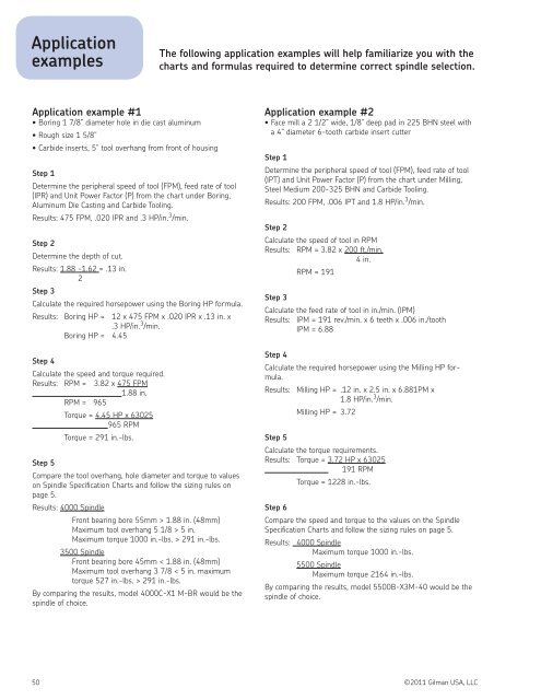
ApplicationexamplesThe following application examples will help familiarize you with thecharts <strong>and</strong> formulas required to determine correct spindle selection.Application example #1• Boring 1 7/8” diameter hole in die cast aluminum• Rough size 1 5/8”• Carbide inserts, 5” tool overhang from front of housingStep 1Determine the peripheral speed of tool (FPM), feed rate of tool(lPR) <strong>and</strong> Unit Power Factor (P) from the chart under Boring,Aluminum Die Casting <strong>and</strong> Carbide Tooling.Results: 475 FPM, .020 IPR <strong>and</strong> .3 HP/in. 3 /min.Step 2Determine the depth of cut.Results: 1.88 -1.62 = .13 in.2Step 3Calculate the required horsepower using the Boring HP formula.Results: Boring HP = 12 x 475 FPM x .020 IPR x .13 in. x.3 HP/in. 3 /min.Boring HP = 4.45Step 4Calculate the speed <strong>and</strong> torque required.Results: RPM = 3.82 x 475 FPM1.88 in.RPM = 965Torque = 4.45 HP x 63025965 RPMTorque = 291 in.-lbs.Step 5Compare the tool overhang, hole diameter <strong>and</strong> torque to valueson Spindle Specification Charts <strong>and</strong> follow the sizing rules onpage 5.Results: 4000 SpindleFront bearing bore 55mm > 1.88 in. (48mm)Maximum tool overhang 5 1/8 > 5 in.Maximum torque 1000 in.-lbs. > 291 in.-lbs.3500 SpindleFront bearing bore 45mm < 1.88 in. (48mm)Maximum tool overhang 3 7/8 < 5 in. maximumtorque 527 in.-lbs. > 291 in.-lbs.By comparing the results, model 4000C-X1 M-BR would be thespindle of choice.Application example #2• Face mill a 2 1/2” wide, 1/8” deep pad in 225 BHN steel witha 4” diameter 6-tooth carbide insert cutterStep 1Determine the peripheral speed of tool (FPM), feed rate of tool(lPT) <strong>and</strong> Unit Power Factor (P) from the chart under Milling,Steel Medium 200-325 BHN <strong>and</strong> Carbide Tooling.Results: 200 FPM, .006 IPT <strong>and</strong> 1.8 HP/in. 3 /min.Step 2Calculate the speed of tool in RPMResults: RPM = 3.82 x 200 ft./min.4 in.RPM = 191Step 3Calculate the feed rate of tool in in./min. (IPM)Results: IPM = 191 rev./min. x 6 teeth x .006 in./toothIPM = 6.88Step 4Calculate the required horsepower using the Milling HP formula.Results: Milling HP = .12 in. x 2.5 in. x 6.881PM x1.8 HP/in. 3 /min.Milling HP = 3.72Step 5Calculate the torque requirements.Results: Torque = 3.72 HP x 63025191 RPMTorque = 1228 in.-lbs.Step 6Compare the speed <strong>and</strong> torque to the values on the SpindleSpecification Charts <strong>and</strong> follow the sizing rules on page 5.Results: 4000 SpindleMaximum torque 1000 in.-lbs.5500 SpindleMaximum torque 2164 in.-lbs.By comparing the results, model 5500B-X3M-40 would be thespindle of choice.50 ©2011 <strong>Gilman</strong> <strong>USA</strong>, LLC


