CNS STANDARD OPERATING PROCEDURE Two Photon ...
CNS STANDARD OPERATING PROCEDURE Two Photon ...
CNS STANDARD OPERATING PROCEDURE Two Photon ...

You also want an ePaper? Increase the reach of your titles
YUMPU automatically turns print PDFs into web optimized ePapers that Google loves.
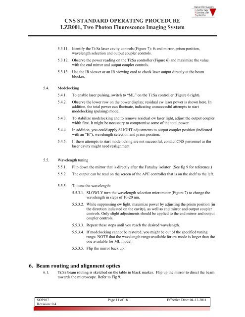
<strong>CNS</strong> <strong>STANDARD</strong> <strong>OPERATING</strong> <strong>PROCEDURE</strong>LZR001, <strong>Two</strong> <strong>Photon</strong> Fluorescence Imaging System5.3.11. Identify the Ti:Sa laser cavity controls (Figure 7): fs end mirror, prism position,wavelength selection and output coupler controls.5.3.12. Observe the power reading on the Ti:Sa controller (Figure 6) and maximize the valuewith the end mirror and output coupler controls.5.3.13. Use the IR viewer or an IR viewing card to check laser output directly at the beamblocker.5.4. Modelocking5.4.1. To enable laser pulsing, switch to “ML” on the Ti:Sa controller (Figure 6 right).5.4.2. Observe the lower row on the power display; residual cw laser power is shown here. Inaddition, the total power can fluctuate, indicating unsuccessful attempts to startmodelocking (pulsing) mode.5.4.3. To stabilize modelocking and to remove residual cw laser light, adjust the output couplerwidth first. It might be necessary to compromise some of the total power.5.4.4. In addition, you could apply SLIGHT adjustments to output coupler position (indicatedwith an “H”), wavelength selection and prism position.5.4.5. If these attempts to start modelocking are not successful, contact <strong>CNS</strong> personnel as thelaser cavity might need realignment.5.5. Wavelength tuning5.5.1. Flip down the mirror that is directly after the Faraday isolator. (See fig 9 for reference.)5.5.2. The output can be read on the screen of the APE controller that is on the shelf to the left.5.5.3. To tune the wavelength:5.5.3.1. SLOWLY turn the wavelength selection micrometer (Figure 7) to change thewavelength in steps of 10-20 nm.5.5.3.2. While suppressing cw light, maximize power by adjusting the prism position (inthe direction indicated on the cavity), as well as end mirror and output couplercontrols. Only slight adjustments should be applied to the end mirror and outputcoupler controls.5.5.3.3. Repeat these steps until you reach the desired wavelength.5.5.3.4. If modelocking cannot be restored, you might be out of the specified tuningrange. NOTE that the wavelength range available for cw mode is larger than theone available for ML mode!5.5.3.5. Flip the mirror back up.6. Beam routing and alignment optics6.1. Ti:Sa beam routing is sketched on the table in black marker. Flip up the mirror to direct the beamtowards the microscope. Refer to Fig 9.SOP107Revision: 0.4Page 11 of 18 Effective Date: 04-13-2011