GLOBE7 GLOBE7J GLOBE10Power supply 230 V~ / 50-60 Hz 120 V~ / 50-60Hz 230 V~ / 50-60 HzAbsorption 0,7 A 1,4 A 1,2 AFuse F1 F1,6A F3,15A F1,6AThrust 500 N 500 N 900 NMax stroke 2500 mm 2500 mm 2500 mmMax load 7 m² 7 m² 10 m²Opening speed0,15 m/s (chain)0,18 m/s (belt)0,15 m/s (chain)0,18 m/s (belt)0,12 m/s (belt + 71RC1)0,15 m/s (chain)0,18 m/s (belt)Closing speed0,10 m/s (chain)0,12 m/s (belt)0,10 m/s (chain)0,12 m/s (belt)0,10 m/s (chain)0,12 m/s (belt)Service class 3 - FREQUENT 3 - FREQUENT 3 - FREQUENTIntermittence S2 = 30 min / S3= 50% S2 = 30 min / S3= 50% S2 = 30 min / S3= 50%Temperature -20° C / +55° C -20° C / +55° C -20° C / +55° CDegree of protection IP10 IP10 IP10Control Panel 70R 70R 71R (71RC1)2. REFERENCE ILLUSTRATIONS AND ACCESSORIESThe given operating and performance features can only be guaranteedwith the use of DITEC accessories and safety devices.2.1 Standard installation references (fig. 1)[1] Radio[2] Drive unit[3] Retention bracket[4] Slide[5] Release cord[6] Guide[7] Guide coupling[8] Transmission[9] Photocells[10] Sensitive edge[11] Transmitter support[12] Connect the power supply to an omnipolar switch with contact openingdistance of at least 3 mm (not supplied by us) or by means of power plug.Connection to supply mains must be carried out in an independent racewayseparate from control connections and safety device connections.2.2 AccessoriesBATK1 Battery kitGLOBEC Adapter for up and over doors with counterweightsASB1 External release kit with cord and lock L=900 mmASB2 Cord release device L= 2000 mmGLOBEL Extension set for 1120 mm chainGLOBELV Extension set for 1120 mm belt (for steel guide only)GLOBEFM Additional close stopGLOBESI Intermediate supportGLOBEGF Iron track L=3000 mmGLOBEGA Aluminium track L=3000 mm3. INSTALLATION3.1 Chain type GLOBE assembly (fig. 4)- Extend the chain.- Fit the coupling [1] as far as the guide stop. Fit the guide [2] asfar as the stop. Fit the coupling [3] as far as the guide stop [2].- Superimpose the guide [4] on the coupling [3], correctly fitthe transmission in the guide [4]: lift the guide as shown inthe detail to permit fitting the transmission.- Move the coupling [3] towards the transmission as far asthe guide stop [4].Note: the guides must be fitted in a specific direction (see stops[x] shown in illustration).3.2 Belt type GLOBE assembly (fig.5)- (fig. 5a) Fit the belt to the transmission and slide.- (fig. 5b) Fit the belt stop as shown in the illustration.- (fig. 5c) Fasten the two ends of the belt to the release pinby means of the couplings keeping to the pin directionshown in the illustration.- (fig. 5d) Fit the drive pin (belt - transmission - slide) in the guide.- (fig. 5e) Pass the belt around the pulley and secure bymeans of the pin [Y]. Fit the guide as shown in fig. 3, lockin the drive unit as far as the stop and tighten screw [K].- (fig. 5f) Push the transmission towards the outside of theguide and fasten the retention bracket to the wall.3.3 Chain or belt tensioning (fig.6)- Correct tensioning is achieved by leaving 1÷2 mm betweenthe spring retainer [E] and stop [H] to enable the spring [E]to work in the best possible way.Attention: over-tightening could affect proper operation of theautomatic system.3.4 GLOBE installation (fig. 7-8)- Establish and trace the retention point of the guide on thewall and ceiling (fig. 7a).Attention: in the case of spring balanced up and over doors withcounterweights use GLOBEC (fig. 7b). With the off-board driveunit, fit the guide to the wall using the transmission bracket (fig. 7c).(fig. 7d) Fit the bracket [3] and secure using the screwsprovided. Lift the unit and bend the brackets to measure (ifnecessary eliminate the excess parts), then fasten to the ceiling.Attention: (fig. 8) to fully open sectional doors with specialheights, the arm [M] can be shortened and the coupling point[L] can be moved from 20 mm to 100 mm further in than [G].If necessary, fit a shim [J] (not supplied by us, max 200 mm)between the wall and the tightener [L]. This way the stroke of theslide will be increased by exploiting all the available guide.- Manually release (see OPERATING INSTRUCTIONS)and move the slide up to the closed door, then fit the retentionbracket [G] on the top edge, possibly interposingthe supplied reinforcing angular [P] (fig.8c-d); afterwards,re-lock the slide by moving the door manually.- (Fig. 9) Fit the stop in the guide and secure in the desiredopening position.- (Fig. 10) For stronger fastening the intermediate supportGLOBESI can be installed.GLOBE - IP183918
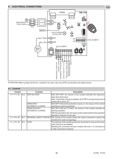
4. ELECTRICAL CONNECTIONSGBOPEN70R-71RANTAlimentazionePower supplyF1TRANSF.24 V~ BATJR4SOPRGSIGMotor24V=BATK1Nero / BlackBlu / BlueENCLuce di cortesiaCourtesy light-M+MOnly GLOBE10JR3JR2ONBIXMR2COMOFF 1 2 3 4 5 6POWERALARMSAOnly GLOBE101513140 1 5 8 9 R1 TCElettroserratura / Electric lockLampada / LampLampeggiante / Flashing lightUscita / Output 24 V= / 0,3 APasso-passo / Step by stepSicurezza di inversione /Reversal safety contactStopATTENTION: Make a jumper all the N.C. contacts if not used. Use only DITEC accessories and safety devices.4.1 ControlsControl Function Description1 5 N.O. STEP-BY-STEP With DIP1=OFF the closure of the contact activates the sequence:open-stop-close-open.Note: if automatic closing is enabled, the STOP is not permanent but ata time that is set by TC.OPEN WITHAUTOMATIC CLOSINGWith DIP1=ON and the automatic closure on, the closure of the contactactivates an opening operation.OPEN WITHOUTAUTOMATIC CLOSINGWith DIP1=ON and TC=MAX, the closure of the contact activates anopening operation.With the automation idle, the closure of the contact performs the operationopposite to that prior to the stop.1 8 N.C. REVERSAL SAFETY CONTACT The closing of the contact during the closure manoeuvre causes themovement to invert (re-opening).1 9 N.C. STOP The opening of the contact causes the movement to stop and the automaticclosure to be disabled.Resetting the command, the door remains still until a 1-5 command ora radio command is received.19 GLOBE - IP1839