Telenium IP install.pdf - TierOne Telecommunications
Telenium IP install.pdf - TierOne Telecommunications
Telenium IP install.pdf - TierOne Telecommunications

Create successful ePaper yourself
Turn your PDF publications into a flip-book with our unique Google optimized e-Paper software.
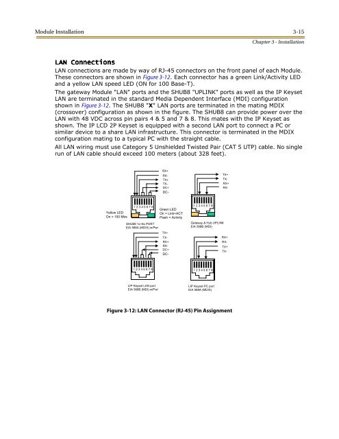
Module Installation 3-15Chapter 3 - InstallationLAN ConnectionsLAN connections are made by way of RJ-45 connectors on the front panel of each Module.These connectors are shown in Figure 3-12. Each connector has a green Link/Activity LEDand a yellow LAN speed LED (ON for 100 Base-T).The gateway Module "LAN" ports and the SHUB8 "UPLINK" ports as well as the <strong>IP</strong> KeysetLAN are terminated in the standard Media Dependent Interface (MDI) configurationshown in Figure 3-12. The SHUB8 "X" LAN ports are terminated in the mating MDIX(crossover) configuration as shown in the figure. The SHUB8 can provide power over theLAN with 48 VDC across pin pairs 4 & 5 and 7 & 8. This mates with the <strong>IP</strong> Keyset asshown. The <strong>IP</strong> LCD 2P Keyset is equipped with a second LAN port to connect a PC orsimilar device to a share LAN infrastructure. This connector is terminated in the MDIXconfiguration mating to a typical PC with the straight cable.All LAN wiring must use Category 5 Unshielded Twisted Pair (CAT 5 UTP) cable. No singlerun of LAN cable should exceed 100 meters (about 328 feet).RX+RX-TX+TX-DC+DC-TX+TX-RX+RX-Yellow LEDOn = 100 Mbs1 2 3 4 5 6 7 8SHUB8 1x~8x PORTEIA 568A (MDIX) w/PwrTX+TX-RX+RX-DC+DC-Green LEDOn = Link+ACTFlash = Activity1 2 3 4 5 6 7 8Gateway & Hub UPLINKEIA 568B (MDI)RX+RX-TX+TX-1 2 3 4 5 6 7 81 2 3 4 5 6 7 8L<strong>IP</strong> Keyset LAN portEIA 568B (MDI) w/PwrL<strong>IP</strong> Keyset PC portEIA 568A (MDIX)Figure 3-12: LAN Connector (RJ-45) Pin Assignment