4 - Big Ass Fans
4 - Big Ass Fans
4 - Big Ass Fans

You also want an ePaper? Increase the reach of your titles
YUMPU automatically turns print PDFs into web optimized ePapers that Google loves.
Installation Guide:Oct. 2013Rev. F<strong>Big</strong> <strong>Ass</strong> Fan Company2348 Innovation DriveLexington, KY 405111-877-BIG-FANSwww.bigassfans.comMay be covered by one or more of the following United States Patents:6244821; 6589016; 6817835; 6939108; 7252478; 7284960; D607988; D587799; 7654798; D642674; 7934907; 8079823; D635237;D641075; D650893; D642674; 8075273; D650893; 8147182; 8147204; 8152453; and other patents pending.Yellow Jacket and the Yellow Jacket logo are trademarks of Delta T Corporation, registered in the United States and/or other countries.
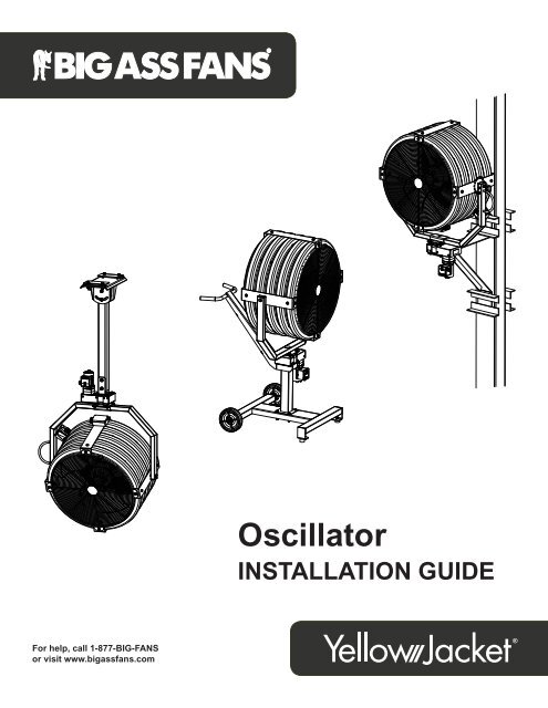
ContentsIntroductionSafety Instructions iiPortable BaseParts and Hardware 1Installing the Oscillator 1. <strong>Ass</strong>emble Portable Base 12. Attach Handle and Second Pedestal 23a. Install Handle and Oscillator <strong>Ass</strong>embly (one pedestal) 23b. Install Oscillator <strong>Ass</strong>embly (two pedestals) 34. Install Fan Yoke 35. Adjust Angle of Oscillation (optional) 46. Remove Original Speed Control Cover 47. Install New Speed Control Cover and Complete Wiring 4Wiring the Oscillator Wiring Diagram: 10 Lead SNTech Motors 5Wiring Diagram: 6 Lead Genteq ® Motors 6Column/Yoke MountParts and Hardware 7Installing the Oscillator 1. Install Wall/Column Supports or Yokes 82. Modify Original Speed Control 83. Install Oscillator <strong>Ass</strong>embly 84. Install Fan Yoke 95. Install Junction Box 106. Adjust Angle of Oscillation (optional) 117. Install Remote Speed Control 118. Install Safety Cable 12Wiring the Oscillator Wiring Diagram: 10 Lead SNTech Motors 13Wiring Diagram: 6 Lead Genteq ® Motors 14
YELLOW JACKET ®Portable Base Oscillator Installation1The following instructions are for installing the Oscillator accessory on a Yellow Jacket ® fan that is mounted to a portable base. Consultthe complete Yellow Jacket Installation Guide for all other aspects of fan installation, operation, and safety information.WARNING: Disconnect the fan from power before installation!WARNING: Do not prevent the oscillator from rotating when in operation!CAUTION: If you purchased the misting system, be sure to install the oscillator before installing the misting system!Parts and hardwareThe parts and hardware listed below are intended for the oscillator option on a Yellow Jacket with a portable base mount. For a list ofcolumn/yoke mount parts and hardware, see page 7. For a complete list of fan components, see the Yellow Jacket Installation Guide. Ifyou are missing any parts or hardware required for installation, contact Customer Service at 1-877-BIG-FANS.Note: The illustrations below are not to scale.(8) 3/8” Washer Cord Grip ConnectorOscillator <strong>Ass</strong>emblySpeed ControlCoverHandle(8) 3/8-16 x 3/4” HexHead Cap Screw(3) Yellow Wire NutInstalling the oscillatorwashers, (4) nuts, and fan yoke assembly from the pedestal. Discard the used hardware.(8) washers, (4) nuts, and fan yoke assembly from the upper pedestal. Discard the used hardware. Next, remove the (4) bolts, (8)washers, and (4) nuts (Pedestal Hardware) and the upper pedestal from the lower pedestal. Set the Pedestal Hardware aside. You willuse it to reattach the upper pedestal and handle to the lower pedestal.1. <strong>Ass</strong>emble portable baseIn the complete Yellow Jacket Installation Guide, follow the steps under “Mounting Method: Portable Base” to secure the wheels andpedestal to the portable base. If you are installing two pedestals, do not attach the second pedestal yet.Attach Wheels (to Portable Base)Attach Pedestal (to Portable Base)WWW.BIGASSFANS.COM ©2012 DELTA T CORP. DBA BIG ASS FAN ALL RIGHTS RESERVED
YELLOW JACKET ®Portable Base Oscillator Installation (cont.)33b. Install oscillator assembly (two pedestals)If you are not installing two pedestals, skip this step and proceed to step 4.shown. The inner portion of the oscillator enclosure has (4) weld nuts to which the bolts should attach. Ensure the oscillator motor isoriented as shown.Proceed to step 4.Lower Oscillator Hardware (BAF-Supplied):a. (4) 3/8-16 x 3/4” Hex Head Cap Screwb. (4) 3/8” Washerba4. Install fan yokeSecure the fan yoke to the oscillator bracket. Position the yoke so that the yoke handle is on the same side as the oscillator motor asshown.Upper Oscillator Hardware (BAF-Supplied):a. (4) 3/8-16 x 3/4” Hex Head Cap Screwb. (4) 3/8” WasherabYokeHandleYokeHandleOne pedestalTwo pedestalsWWW.BIGASSFANS.COM ©2012 DELTA T CORP. DBA BIG ASS FAN ALL RIGHTS RESERVED
YELLOW JACKET ®4 Portable Base Oscillator Installation (cont.)The oscillator arm is preset to oscillate a full 60 degrees;however, the angle of oscillation can be adjusted and set to 45°,60°, or 90°. The innermost hole is 90°, the middle hole is 60°,and the outermost hole is 45°.To adjust the angle of oscillation, remove the oscillator enclosurecover by unscrewing the (8) screws. Remove the lock nutfrom the bottom of the crank rod, adjust the rod end, and thenreinstall the nut.9060456. Remove original speed control coverWARNING: Disconnect the fan from power before replacingthe cover!Remove the original cover from the speed control by unscrewing the(4) cover fasteners. Disconnect the wiring to the speed control knob,and then remove the speed knob from the original cover and set itaside.SpeedKnobOn the fan, disconnect all wiring except the yellow, purple, and grayleads to the motor (if present). Remove the 1/2” hole seal from thebottom of the control box.7. Install new speed control cover andcomplete wiringWARNING: Disconnect the fan from power!Install the speed control knob on the new speedcontrol cover. Make sure the knob is turned all the waycounterclockwise and that the line is pointing to theOFF position. Note: If the speed knob will not line upproperly, loosen the square brass barrel in the speedknob shaft, adjust the knob, and then reinstall. If theposition is still inaccurate, repeat this process until it iscorrected.Route and secure the oscillator power cord to the newcord grip connector on the speed control box. Verifythe cords will have enough slack to accommodate foroscillating motion.Complete all wiring connections as shown in theappropriate wiring diagram on page 5 or page 6. Installthe new speed control cover on the junction box withthe (4) screws.Note: Wiring and power cord are not shown in the illustration above.WWW.BIGASSFANS.COM ©2012 DELTA T CORP. DBA BIG ASS FAN ALL RIGHTS RESERVED
YELLOW JACKET ®Portable Base Oscillator Installation (cont.)Wiring the oscillator: 10 lead SNTech motors5CAUTION: The installation of a <strong>Big</strong> <strong>Ass</strong> manual and with any additional requirements set forth by the National Electric Code (NEC), ANSI/NFPA 70-2011, and alllocal codes. Code compliance is ultimately YOUR responsibility!If the motor has ten (10) leads, it is an SNTech motor. If the motor has six (6) leads, it is a Genteq ® motor. See thefollowing page for 6 lead Genteq wiring instructions.SN-ECMBlackRed 1GrayGrayPurpleYellowBlackPinkOrangeRedWhiteGreen w/Yellow TracerFan MotorOscillator MotorBlackRed 2Green w/ Yellow eo TracerBlackWhiteGreenBlackRed 1100k ΩBlackRed 2Green w/ Yellow TracerBlackWhite GreenWWW.BIGASSFANS.COM ©2012 DELTA T CORP. DBA BIG ASS FAN ALL RIGHTS RESERVED
Parts and hardwareYELLOW JACKET ®Column/Yoke Mount Oscillator InstallationThe following instructions are for installing the Oscillator accessory on a Yellow Jacket ® fan that is mounted to a wall, column, or I-beam.Consult the complete Yellow Jacket Installation Guide for all other aspects of fan installation, operation, and safety information.WARNING: Do not prevent the oscillator from rotating when in operation!CAUTION: If you purchased the misting system, be sure to install the oscillator before installing the misting system!WARNING: The safety cable is an important part of the fan installation and must be installed correctly!The parts and hardware listed below are intended for the oscillator option on a Yellow Jacket with a yoke mount or column/wall mount.For a list of portable base mount parts and hardware, see page 1. For a complete list of fan parts and hardware, see the Yellow JacketInstallation Guide. If you are missing any parts or hardware required for installation, contact Customer Service at 1-877-BIG-FANS.Note: The illustrations below are not to scale.7OscillatorOscillator <strong>Ass</strong>embly(4) 3/8-16 x 1”Hex Head CapSpeed Control ScrewCover Kit 1 (4) 3/8-16 x 1-1/4”Hex Head CapScrew(8) 3/8” WasherCord GripConnector1/2” NylonLocknut(3) YellowWire NutRemotely Mounted Speed ControlRemote SpeedControl Box(3) 1/2” NylonLocknut300V RMS CableCorrugatedConduit1/2” Nylon ConduitFitting(3) Cord GripConnector(2) 8-18 x 1/2”Self-drilling Screw(9) OrangeWire NutJunction BoxSafety CableSafety Cable 2 (2) Gripple ®3 & (2) Wire Rope Clip 3 OR Shackle 31. The Speed Control Cover kit includes two pre-installed oscillator switch wires.2. The safety cable is only installed on fans mounted to columns or the Yoke Mount. For Yoke Mount installations, the safety cable will have two looped ends.3. Gripples and wire rope clips are included with the Column Mount only. Shackles are included with the Yoke Mount only.Note: Two feet of 16 GA wire in the following colors is also provided: black, orange, red, white, green with yellow tracer, and pink.Note: The Column Mount hardware includes an additional bolt, nut, and two washers. This hardware is not needed for oscillator installation.WWW.BIGASSFANS.COM ©2012 DELTA T CORP. DBA BIG ASS FAN ALL RIGHTS RESERVED
YELLOW JACKET ®8Column/Yoke Mount Oscillator Installation (cont.)Installing the oscillatorIf you are installing the oscillator on a previously assembled fan, remove the (4) bolts, (8) washers, (4) nuts, and fan yoke assemblyfrom the wall/column supports or yoke mount.1. Install wall/column supports or yokesIn the complete Yellow Jacket ® Installation Guide, follow the steps to install the wall supports, column supports, or the upper yoke,extension tube, and lower yoke brackets.2. Modify original speed controlRemove the speed knob from the original cover and set it aside. Disconnect all wiring except the yellow, purple, and gray leads to themotor (if present). Remove the power cord and original cord grip connector from the back of the box, and then install the provided nylonSpeedControlKnobCord GripConnectorSpeedControlCover3. Install oscillator assemblyAttach the oscillator assembly to the wall/column supports or lower yoke as shown. The inner portion of the oscillator enclosure has (4)weld nuts to which the bolts should attach. Ensure the oscillator motor is oriented as shown.Upper Oscillator Hardware (BAF-Supplied):a. (4) 3/8-16 x 1-1/4” Hex Head Cap Screwb. (4) 3/8” WasherabbaWall/Column SupportsYoke MountWWW.BIGASSFANS.COM ©2012 DELTA T CORP. DBA BIG ASS FAN ALL RIGHTS RESERVED
YELLOW JACKET ®10 Column/Yoke Mount Oscillator Installation (cont.)<strong>Big</strong> <strong>Ass</strong> <strong>Fans</strong> does not supply the cable needed to install the oscillator On/Off switch.a. Remove the cover from the junction box, and then secure the junction box to the fan brace with the Junction Box Hardware asshown. Note: Install the junction box on the yoke side of the fan closest to the supports.b. Route and install the provided corrugated conduit and enclosed wiring from the junction box to the speed control junction box (on thefan). Press the conduit into the connectors.c. Route the oscillator cord to the junction box and secure it to the designated connector. Note: It is critical that the fan orientation andangle is set before routing the cord.d. Install the cord grip connector and power cord (previously removed from original speed control) in the open 1/2” connector hole onthe junction box.e. Strip 5” of outer jacket off of the remote speed control cables. Install the cables in the (2) cord grip connectors for the Speed Knoband the On/Off Switch.Junction Box Hardware (BAF-Supplied):a. (2) 8-18 x 1/2” Hex Head Self-drilling ScrewCorrugated ConduitJunctionBoxOscillatorOriginalSpeedControlCord GripConnector &Fan Power CordSpeedKnobOn/OffSwitch(Remote Speed Control)CoveraJunctionBoxNote: The mounting method or fan orientation may differ fromthe illustration above.WWW.BIGASSFANS.COM ©2012 DELTA T CORP. DBA BIG ASS FAN ALL RIGHTS RESERVED
YELLOW JACKET ®Column/Yoke Mount Oscillator Installation (cont.)11The oscillator arm is preset to oscillate a full 60 degrees; however, the angle of oscillation can be adjusted and set to 45°, 60°, or 90°.The innermost hole is 90°, the middle hole is 60°, and the outermost hole is 45°.To adjust the angle of oscillation, remove the oscillator enclosure cover by unscrewing the (8) screws. Remove the lock nut from thebottom of the crank rod, adjust the rod end, and then reinstall the nut.9060457. Install remote speed controla. On the remote speed control, remove the cover and install it on the fan speed control. The original speed control on the fan can bediscarded.b. On the remote speed control, install the new cover (with knob). Make sure the knob is pointing to the OFF position. Note: If thespeed knob does not line up properly, loosen the square brass barrel in the speed knob shaft, and then reinstall. If the position is stillinaccurate, repeat this process until it is corrected.c. Mount the remote speed control box to a suitable wall or column no more than 30 ft from the fan. Make sure the (2) connector holesare facing the ceiling.d. Route and secure the speed control and oscillator switch cables to the new cord grip connectors on the remote speed control box.e. Verify the cord will have enough slack to accommodate oscillating motion. Note: The Oscillator Remote Speed Control kit is providedwith 15 ft of cable; however, the control can be mounted up to 30 ft from the location of the fan using customer-supplied cable.f. Complete all wiring connections as shown in the appropriate wiring diagram on page 13 or page 14.WWW.BIGASSFANS.COM ©2012 DELTA T CORP. DBA BIG ASS FAN ALL RIGHTS RESERVED
YELLOW JACKET ®12 Column/Yoke Mount Oscillator Installation (cont.)8. Install safety cableWARNING: The safety cable is a crucial part of the fan and must be installed correctly. If you have any questions, callCustomer Service at 1-877-BIG-FANS.CAUTION: Ensure there is enough slack in the safety cable to accommodate for the oscillating motion!Column MountRoute one end of the safety cable through a Gripple ® , and thenloop the cable around the column and back through the Grippleas shown. Route the cable through the second Gripple, aroundthe fan yoke, and then back through the second Gripple asshown.Note: Ensure the safety cable is secured to the column abovethe Column Mount brackets. Ensure the cable is secured to thefan yoke in the location shown below. If the cable is securedtoo high on the fan yoke, it may slide down the yoke duringoperation.Pull the loose ends of the cable through the Gripples until thecable is drawn tightly around the column and fan yoke. Test thefan to ensure there will be enough slack in the safety cable toaccommodate for the oscillating motion. Secure the loose endsof the cable with the two (2) wire rope clips and torque to4.5 ft·lb (6.1 N·m).Yoke MountWrap the safety cable around the mounting structure, andthen secure it with the shackle as shown below. Test the fanto ensure there will be enough slack in the safety cable toaccommodate for the oscillating motion.SafetyCableShackleGripple ®SafetyCableWire RopeClipWWW.BIGASSFANS.COM ©2012 DELTA T CORP. DBA BIG ASS FAN ALL RIGHTS RESERVED
14YELLOW JACKET ®Column/Yoke Mount Oscillator Installation (cont.)Wiring the oscillator: 6 lead Genteq ® motorsCAUTION: The installation of a <strong>Big</strong> <strong>Ass</strong> manual and with any additional requirements set forth by the National Electric Code (NEC), ANSI/NFPA 70-2011, and alllocal codes. Code compliance is ultimately YOUR responsibility!If the motor has six (6) leads, it is a Genteq ® motor. If the motor has ten (10) leads, it is an SNTech motor. See theprevious page for 10 lead SNTech wiring instructions.Fan MotorOrangeVioletBlackRedWhiteGreen w/Yellow TracerJunction BoxGreenWhiteBlackFan Power CordBlackVioletOrangeRedWhiteGreenGreen w/ YellowRed 1Red 2Customer-supplied WireOscillator Motor100k ΩRemote Speed Control60GreenWhiteRedBlackVioletOrangeBlackVioletOrangeRedWhiteGreenJunction BoxZoomGreenWhiteBlackGreen w/ YellowRed 1Red 2WWW.BIGASSFANS.COM ©2012 DELTA T CORP. DBA BIG ASS FAN ALL RIGHTS RESERVED
*002582*002582Rev. F2348 Innovation Drive Lexington, KY 40511 1-877-BIG-FANS