2 - Big Ass Fans
2 - Big Ass Fans
2 - Big Ass Fans
- No tags were found...

Create successful ePaper yourself
Turn your PDF publications into a flip-book with our unique Google optimized e-Paper software.
8’–24’ POWERFOIL ® X2.0 WASHDOWN & POWERFOIL ® X2.0PLUS WASHDOWNInstallation ChecklistDo you have the appropriate mount to accommodate your roof pitch? If you are uncertain orfeel you have the incorrect mount for your building structure, please contact Customer Service at1-877-BIG-FANS.Did a structural engineer approve the mounting structure? See page 9 for <strong>Big</strong> <strong>Ass</strong> <strong>Fans</strong>-approvedmounting structures.Are you familiar with the function and use of the safety cable? See page 19 for information onproperly securing the safety cable.Will the fan be installed so that the airfoils have at least 2 ft (0.61 m) of clearance fromobstructions?Will the fan be installed so that it is not subjected to high winds such as from an HVAC systemor near a large garage door? If the fan is mounted at the same level or higher than a diffuser, thewinglets must be at a distance that is at least 1x the measure of the fan’s diameter. If the fan is mountedat the same height or below a diffuser, the winglets must be at a distance that is at least 2x the measureof the fan’s diameter.Will the distance between multiple fans be at least 2.5x the fans’ diameter when measured fromthe centers of the fans.If installing the fan on an I-beam, ensure the upper yoke is the correct size. See page 12 for moreinformation on installing the fan to an I-beam.If you ordered multiple fans, did you keep the parts for each fan together? It is critical that the airfoilsbe properly matched with the motor unit.Do you have the correct power circuit for the fan controller? See pages 2–3 for informationconcerning power requirements for the fan controller.Customer Service: 1-877-BIG-FANS(International: 1-859-233-1271)WWW.BIGASSFANS.COM ©2012 DELTA T CORP. DBA BIG ASS FAN CO. ALL RIGHTS RESERVED
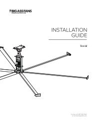
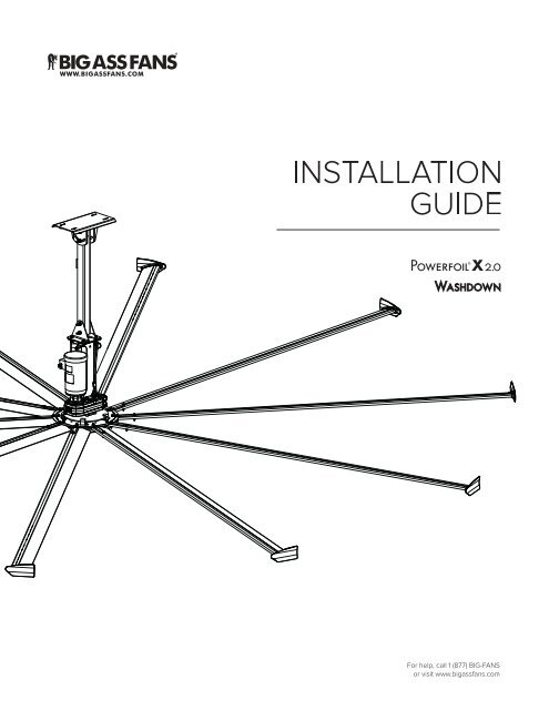
8’–24’ POWERFOIL ® X2.0 WASHDOWN & POWERFOIL ® X2.0PLUS WASHDOWNInstallation Guide8’–24’ Powerfoil ® X2.0 WashdowniInstallation Guide:Oct. 2013Rev. FThis product was manufactured in a plant whose Management3128438Conforms to ANSI/UL STD 507: Electric <strong>Fans</strong>Contact InformationManufacturing2425 Merchant StreetLexington, KY 405111-877-BIG-FANSwww.bigassfans.comCustomer Service2348 Innovation DriveLexington, KY 405111-877-BIG-FANSwww.bigassfans.comWarranty Returns800 Winchester RoadLexington, KY 405051-877-BIG-FANSwww.bigassfans.comUnit 4, 5 McPhall RoadCoomera QLD 4209(07) 550 0690www.bigassfans.com.auEU Authorized RepresentativeA L U R A G R O U PZwolsestraat 1562587 WB The Hague,The NetherlandsPh.: +31 70 250 0353PowerfoilX2.0 and the PowerfoilX2.0 logo are trademarks of Delta T Corporation, registered in the United States and/or other countries. All other trademarks used herein are the propertiesof their respective owners. No part of this document may be reproduced or translated into a different language without the prior written consent of <strong>Big</strong> <strong>Ass</strong> Fan Company. The informationcontained in this document is subject to change without notice.May be covered by one or more of the following United States Patents: 6244821; 6589016; 6817835; 6939108; 7252478; 7284960; D607988; D587799; 7654798; D642674; 7934907;8079823; D635237; D641075; D650893; D642674; 8075273; D650893; 8147182; 8147204; 8152453; and other patents pending.WWW.BIGASSFANS.COM ©2012 DELTA T CORP. DBA BIG ASS FAN CO. ALL RIGHTS RESERVED
ii8’–24’ POWERFOIL ® X2.0 WASHDOWN & POWERFOIL ® X2.0PLUS WASHDOWNIMPORTANT SAFETY INSTRUCTIONSREAD AND SAVE THESE INSTRUCTIONSTO REDUCE THE RISK OF FIRE, ELECTRIC SHOCK, OR INJURY TO PERSONS, OBSERVE THE FOLLOWING:WARNING: Before servicing or cleaning unit, switch power off at service panel and lock the service disconnecting means toprevent power from being switched on accidentally. When the service disconnecting means cannot be locked, securely fasten aprominent warning device, such as a tag, to the service panel.WARNING: <strong>Big</strong> <strong>Ass</strong> <strong>Fans</strong> must be installed with <strong>Big</strong> <strong>Ass</strong> Fan-supplied controllers. Other parts cannot be substituted.CAUTION: The installation of a <strong>Big</strong> <strong>Ass</strong> and with any additional requirements set forth by the National Electric Code (NEC), ANSI/NFPA 70-2011, and all local codes. Codecompliance is ultimately YOUR responsibility! Failure to comply with these codes could result in personal injury or propertydamage.WARNING: The fan controllers contain high voltage capacitors which take time to discharge after removal of mains supply. Beforeservicing the fan controller, ensure isolation of mains supply from line inputs at the controller. Wait three minutes for capacitorsto discharge to safe voltage levels. Failure to do so may result in personal injury or death. Note: Darkened display LEDs are not anindication of safe voltage levels.CAUTION: Exercise caution and common sense when powering the fan. Do not connect the fan to a damaged or hazardous powersource. Do not attempt to resolve electrical malfunctions or failures on your own. Contact <strong>Big</strong> <strong>Ass</strong> <strong>Fans</strong> at 1-877-BIG-FANS if youhave any questions regarding the electrical installation of this fan.CAUTION: When service or replacement of a component in the fan requires the removal or disconnection of a safety device, thesafety device is to be reinstalled or remounted as previously installed.power supply before servicing.CAUTION: Do not bend the airfoils when installing, adjusting, or cleaning the fan. Do not insert foreign objects between rotatingfan airfoils.WARNING: Stay alert, watch what you are doing, and use common sense when installing fans. Do not install fans if tired or understandards.CAUTION: Use this fan only in the manner intended by the manufacturer. If you have questions, contact the manufacturer.CAUTION: The installation of this fan requires the use of some power tools. Follow the safety procedures found in the owner’smanual for each of these tools and do not use them for purposes other than those intended by the manufacturer.CAUTION: The <strong>Big</strong> <strong>Ass</strong> <strong>Fans</strong> product warranty will not cover equipment damage or failure that is caused by improper installation.CAUTION: Do not operate fan with a damaged cord or plug. Return fan to an authorized service facility for examination or repair.WARNING: This appliance is not intended for use by persons (including children) with reduced physical, sensory or mentalcapabilities, or lack of experience and knowledge, unless they have been given supervision or instruction concerning use ofthe appliance by a person responsible for their safety. Children should be supervised to ensure that they do not play with theappliance.Leave this installation guide with the owner of the fan after installation.Suitable for use in wet locations and outdoor use when installed in a GFCI protected branch circuit.ATTENTION: If installing the fan in the United States, the fan must be installed per the following National Fire Protection<strong>Ass</strong>ociation (NFPA) guidelines:• The fan must be centered approximately between four adjacent sprinklers.• • WWW.BIGASSFANS.COM ©2012 DELTA T CORP. DBA BIG ASS FAN CO. ALL RIGHTS RESERVED
8’–24’ POWERFOIL ® ® X2.0PLUS WASHDOWNMounting Reference GuideThe following is intended as a reference guide for Powerfoil ® X2.0 Washdown and Powerfoil ® X2.0Plus Washdown fan mounting methods. See the referenced pages for complete faninstallation and operating instructions. Consult a structural engineer to determine which mounting method best suits your building structure.I-Beam Bar JoistsZ-PurlinsSolid BeamI-Beam (Angled)See page 12 for mountinginstructions.See page 13 for mountinginstructions.See complete instructionsincluded with the Z-PurlinInstallation Kit.See complete instructionsincluded with the L-BracketInstallation Kit.See complete instructionsincluded with the CompoundAngle Mount Installation Kit.WWW.BIGASSFANS.COM ©2012 DELTA T CORP. DBA BIG ASS
8’–24’ POWERFOIL ® X2.0 WASHDOWN & POWERFOIL ® X2.0PLUS WASHDOWNContentsIntroductionSafety Instructions iiMounting Reference GuideiiiThank You 1About <strong>Big</strong> <strong>Ass</strong> <strong>Fans</strong> 1About the Fan 1 2Pre-InstallationWhat’s in the Box 4Parts and Hardware 5Tools Needed 6Understanding Roof Pitch 6Fan Diagram 7Controller Diagram 8Preparing the Work Site 9 10Mounting Structure:I-BeamMounting Structure:Bar JoistsAttach Upper Yoke (to I-Beam) 121. Select Proper Angle Irons 132. Pre-drill Angle Irons 143. Secure Angle Irons (span is longer than 8 ft) 144a. Fasten Single Angle Irons to Roof Structure 154b. Fasten Double Angle Irons to Roof Structure 165a. Attach Upper Yoke (to Angle Irons) 175b. Attach Main Fan Unit (to Angle Irons) 18Hanging the Fan1. Attach Extension Tube (to Upper Yoke) 192. Secure Upper Safety Cable 193. Attach Lower Yoke (to Extension Tube) 204. Attach Main Fan Unit (to Lower Yoke) 20 20Installing Guy Wires1. Attach Locking Carabiners to Main Fan Unit 212. Attach Beam Clamp 213. Route Guy Wire through Gripple ® 234. Install Remaining Guy Wires 23Installing Airfoils1. Attach Winglets to Airfoils 242. Position Airfoils 243. Attach Airfoils to Hub 25Electrical InstallationSafety Guidelines 26Delta Secondary 27Branch Circuit Protection 28Mounting the Variable Frequency Drive (VFD) 29Wiring: Fan Controller (200V–250V Single-Phase, 1 HP) 30Wiring: Fan Controller (200V–250V Single-Phase, 2 HP) 31Wiring: Fan Controller (200V–250V Three-Phase, 1 HP & 2 HP) 32Wiring: Fan Controller (400V–480V Three-Phase, 1 HP & 2 HP) 33Daisy Chaining 34 36 37 38 39Starting, Stopping, and Direction Control 39Changing the Fan Speed 39Cycling through the LED Display Modes 40Toggling the Fan’s Command Source 40WWW.BIGASSFANS.COM ©2012 DELTA T CORP. DBA BIG ASS FAN CO. ALL RIGHTS RESERVED
8’–24’ POWERFOIL ® X2.0 WASHDOWN & POWERFOIL ® X2.0PLUS WASHDOWNContents (cont.)Electrical Installation(cont.)Understanding and Clearing Fan Faults 41Programming and Parameter Changes 41Locking and Unlocking Procedures 42Operating the FanHeating Season 44Cooling Season 44Preventive MaintenanceAnnual Preventive Maintenance 45General Preventive Maintenance 45Annual Maintenance Checklist 47TroubleshootingGeneral Troubleshooting 49E Series Fan Error Codes 50M Series Fan Error Codes 52Warranty ReturnInstructions<strong>Big</strong> <strong>Ass</strong> InstallersReturn Instructions 54Warranty Claim Form Instructions 55Warranty Claim Form 57Responsibility Agreement 58Check-In Procedure 59 61WWW.BIGASSFANS.COM ©2012 DELTA T CORP. DBA BIG ASS FAN CO. ALL RIGHTS RESERVED
About the fan8’–24’ POWERFOIL ® X2.0 WASHDOWN & POWERFOIL ® X2.0PLUS WASHDOWNIntroduction<strong>Ass</strong> assWho we are and what we do<strong>Ass</strong> <strong>Ass</strong> The Powerfoil ® • • • • • 1WWW.BIGASSFANS.COM ©2012 DELTA T CORP. DBA BIG ASS FAN CO. ALL RIGHTS RESERVED
8’–24’ POWERFOIL ® X2.0 WASHDOWN & POWERFOIL ® X2.0PLUS WASHDOWN2 Fan size20 ftMotor size,HP (kW)2.02.0Minimum requiredsupply circuit sizePowerfoil ® Nominaloutput 1Maximum full loadmotor current(as programmed) 2MaxRPMAirfoillengthSuggesteddistance fromceiling 3 2. CAUTION: <strong>Big</strong> <strong>Ass</strong> <strong>Fans</strong> requires that the Powerfoil X2.0 fan be supplied from one of the following types of transformers:575V–600V models: 575V/330V Wye secondary (neutral not utilized)400V–480V models: 480V/277V Wye secondary (neutral not utilized)200V–250V models: 208V/120V Wye secondary (neutral not utilized)240V/120V Delta secondary (Wild/High Phase B)Integration into any other power distribution scheme may result in improper fan operation or premature hardware failure! Seepage 26 for more information.WWW.BIGASSFANS.COM ©2012 DELTA T CORP. DBA BIG ASS FAN CO. ALL RIGHTS RESERVED
8’–24’ POWERFOIL ® X2.0 WASHDOWN & POWERFOIL ® X2.0PLUS WASHDOWN3Fan size20 ftMotor size,HP (kW)2.02.0Minimum required supplycircuit sizePowerfoil ® Nominal output 1Maximum full loadmotor current(as programmed) 2Max RPMAirfoillengthSuggesteddistance fromceiling 3 2. CAUTION: <strong>Big</strong> <strong>Ass</strong> <strong>Fans</strong> requires that the Powerfoil X2.0 Plus fan be supplied from one of the following types oftransformers:575V–600V models: 575V/330V Wye secondary (neutral not utilized)400V–480V models: 480V/277V Wye secondary (neutral not utilized)200V–250V models: 208V/120V Wye secondary (neutral not utilized)240V/120V Delta secondary (Wild/High Phase B)Integration into any other power distribution scheme may result in improper fan operation or premature hardware failure! Seepage 26 for more information.WWW.BIGASSFANS.COM ©2012 DELTA T CORP. DBA BIG ASS FAN CO. ALL RIGHTS RESERVED
4What’s in the box8’–24’ POWERFOIL ® X2.0 WASHDOWN & POWERFOIL ® X2.0PLUS WASHDOWNPre-InstallationIf you ordered multiple fans, be sure to keep the components of each fan together. The fans each have differently ratedcomponents that are not interchangeable.Note: Dashed lines indicate internal boxes. The drawings below are not to scale. Main BoxExtension Tube BoxAirfoil Box 2 Powerfoil ® 2. WWW.BIGASSFANS.COM ©2012 DELTA T CORP. DBA BIG ASS FAN CO. ALL RIGHTS RESERVED
Parts and hardware8’–24’ POWERFOIL ® X2.0 WASHDOWN & POWERFOIL ® X2.0PLUS WASHDOWN5Note: The drawings below are not to scale. No hardware substitutions are acceptable.HardwareUpper Yoke HardwareExtension Tube HardwareLower Yoke HardwareGuy Wire Hardware ®Winglet HardwareAirfoil HardwareMain Fan Unit HardwareMountingAirfoils 2or ® ® 4 6Electrical <strong>Ass</strong> 2. WWW.BIGASSFANS.COM ©2012 DELTA T CORP. DBA BIG ASS FAN CO. ALL RIGHTS RESERVED
6Tools needed8’–24’ POWERFOIL ® X2.0 WASHDOWN & POWERFOIL ® X2.0PLUS WASHDOWN<strong>Ass</strong> Note: This list of suggested tools is notexhaustive. Additional tools may be necessary.Mechanical installationElectrical installationUnderstanding roof pitch<strong>Ass</strong> Standard Upper Yoke90-Degree Offset MountWWW.BIGASSFANS.COM ©2012 DELTA T CORP. DBA BIG ASS FAN CO. ALL RIGHTS RESERVED
Fan diagram8’–24’ POWERFOIL ® X2.0 WASHDOWN & POWERFOIL ® X2.0PLUS WASHDOWN7A. Safety Cable. B. Upper Yoke.C. Extension Tube. D. Lower Yoke. E. VFD Enclosure (not shown). F. Gearbox. G. Motor. H. Hub.I. Airfoil. J. Winglet (Powerfoil ® [shown] or Powerfoil ® Plus). BACDGFHIJWWW.BIGASSFANS.COM ©2012 DELTA T CORP. DBA BIG ASS FAN CO. ALL RIGHTS RESERVED
8Controller diagram8’–24’ POWERFOIL ® X2.0 WASHDOWN & POWERFOIL ® X2.0PLUS WASHDOWNNote: The illustration below does not show wiring.A. Controller Keypad. B. Disconnect.C. Variable Frequency Drive (VFD). D. Fire Relay. E. Fuses.F. Category 5 Cable and Connector.VFD Enclosure (Front View)ABVFD Enclosure (Inner View)BFCEDWWW.BIGASSFANS.COM ©2012 DELTA T CORP. DBA BIG ASS FAN CO. ALL RIGHTS RESERVED
Preparing the work site8’–24’ POWERFOIL ® X2.0 WASHDOWN & POWERFOIL ® X2.0PLUS WASHDOWN9Mechanical installation• ® • <strong>Ass</strong> I-BeamAngle Iron• • • • Safety requirementMinimum distancesHVACDiffuserHVACDiffuserElectrical installation• • <strong>Ass</strong> • • • • • • WWW.BIGASSFANS.COM ©2012 DELTA T CORP. DBA BIG ASS FAN CO. ALL RIGHTS RESERVED
8’–24’ POWERFOIL ® X2.0 WASHDOWN & POWERFOIL ® X2.0PLUS WASHDOWN10Overhead ViewSide ViewWWW.BIGASSFANS.COM ©2012 DELTA T CORP. DBA BIG ASS FAN CO. ALL RIGHTS RESERVED
8’–24’ POWERFOIL ® X2.0 WASHDOWN & POWERFOIL ® X2.0PLUS WASHDOWN11Powerfoil ® X2.0PlusNote:PowerfoilPlus winglets are optional and may not be included in your fan order.TipsNote: Powerfoil X2.0Plus fans deliver air from a much higher angle, resolving many ofthe issues outlined below.• • • • WWW.BIGASSFANS.COM ©2012 DELTA T CORP. DBA BIG ASS FAN CO. ALL RIGHTS RESERVED
8’–24’ POWERFOIL ® X2.0 WASHDOWN & POWERFOIL ® X2.0PLUS WASHDOWN12 Mounting Structure: I-Beam<strong>Big</strong> <strong>Ass</strong> <strong>Fans</strong> can only be hung from an I-beam or bar joists. See the following page for bar joist mounting instructions.Consult a structural engineer for installation methods not covered in this manual.WARNING: The fan should not be installed unless the structure on which the fan is to be mounted is of soundconstruction, undamaged, and capable of supporting the loads of the fan and its method of mounting. A structuralengineer should verify that the structure is adequate prior to fan installation. Verifying the stability of the mountingstructure is the sole responsibility of the customer and/or end user, and <strong>Big</strong> <strong>Ass</strong> <strong>Fans</strong> hereby expressly disclaims anyliability arising therefrom, or arising from the use of any materials or hardware other than those supplied by <strong>Big</strong> <strong>Ass</strong> <strong>Fans</strong>CAUTION: It is not recommended to mount a <strong>Big</strong> <strong>Ass</strong> Fan to a fabricated I-beam. The I-beam on which the fan will mountmust be part of the existing building structure. Do not direct mount the fan to an I-beam.spacer are closer to one edge than the other. Make sure this edge of the spacer is facing the I-beam. Small Upper YokeI-beamUpper yokemounting holesouter holesmiddle holesinner holesUpper Yoke(top view)Large Upper YokeI-beamUpper yokemounting holesaSide VieweSpacers are only used if3/8” (1 cm).Note: Ensure the spacers are oriented as shown above.WWW.BIGASSFANS.COM ©2012 DELTA T CORP. DBA BIG ASS FAN CO. ALL RIGHTS RESERVED
8’–24’ POWERFOIL ® X2.0 WASHDOWN & POWERFOIL ® X2.0PLUS WASHDOWNMounting Structure: Bar Joists<strong>Big</strong> <strong>Ass</strong> <strong>Fans</strong> can only be hung from an I-beam or bar joists. See the previous page for I-beam mounting instructions.Consult a structural engineer for installation methods not covered in this manual.WARNING: The fan should not be installed unless the structure on which the fan is to be mounted is of soundconstruction, undamaged, and capable of supporting the loads of the fan and its method of mounting. A structuralengineer should verify that the structure is adequate prior to fan installation. Verifying the stability of the mountingstructure is the sole responsibility of the customer and/or end user, and <strong>Big</strong> <strong>Ass</strong> <strong>Fans</strong> hereby expressly disclaims anyliability arising therefrom, or arising from the use of any materials or hardware other than those supplied by <strong>Big</strong> <strong>Ass</strong> <strong>Fans</strong>WARNING: Never use beam clips when mounting the fan to angle irons! Beam clips are only intended for I-beaminstallations.CAUTION: Do not install the fan from a single purlin, truss, or bar joist.CAUTION: The angle irons must be fastened to the roof structure at each end.1. Select proper angle ironsAngle iron spanMinimum angle iron dimensionsNumber of angleirons needed Angle Iron Side View(see table for dimensions)HeightWidthThickness6’ (1.8m) or lessover 6’ (1.8m) - 8’ (2.4m)over 8’ (2.4m) - 12’ (3.7m)WWW.BIGASSFANS.COM ©2012 DELTA T CORP. DBA BIG ASS FAN CO. ALL RIGHTS RESERVED
8’–24’ POWERFOIL ® X2.0 WASHDOWN & POWERFOIL ® X2.0PLUS WASHDOWN14 2. Pre-drill angle ironsmounting structure.Ø 9/16" (1.4cm)A1/2 AMount with extension tube: 5-3/8” (13.7cm)Direct mount: 5-1/2” (14cm)Distance between roofstructure mounting points Proceed to step 4b. aSide ViewWWW.BIGASSFANS.COM ©2012 DELTA T CORP. DBA BIG ASS FAN CO. ALL RIGHTS RESERVED
8’–24’ POWERFOIL ® X2.0 WASHDOWN & POWERFOIL ® X2.0PLUS WASHDOWN4a. Fasten single angle irons to roof structure<strong>Ass</strong> Square Washer3”(7.6 cm)aØ 9/16”(1.4 cm)Thickness:1/4” (6 mm)3”(7.6 cm)WWW.BIGASSFANS.COM ©2012 DELTA T CORP. DBA BIG ASS FAN CO. ALL RIGHTS RESERVED
168’–24’ POWERFOIL ® X2.0 WASHDOWN & POWERFOIL ® X2.0PLUS WASHDOWN4b. Fasten double angle irons to roof structure Square Washer3”(7.6 cm)aØ 9/16”(1.4 cm)3”(7.6 cm)Thickness:1/4” (6 mm)WWW.BIGASSFANS.COM ©2012 DELTA T CORP. DBA BIG ASS FAN CO. ALL RIGHTS RESERVED
8’–24’ POWERFOIL ® X2.0 WASHDOWN & POWERFOIL ® X2.0PLUS WASHDOWNmounting structure. 10-7/8" (27.6 cm) 15-5/8" (39.7 cm)Small Upper Yoke13-3/4’’ (34.9 cm) x9-5/8” (24.4 cm)Large Upper Yoke18-1/2’’(46.9 cm) x9-5/8”(24.4 cm)The angle irons should be aligned with the outermost holes on the upper yoke. Do not use beam clips on angle irons!aSide ViewWWW.BIGASSFANS.COM ©2012 DELTA T CORP. DBA BIG ASS FAN CO. ALL RIGHTS RESERVED
8’–24’ POWERFOIL ® X2.0 WASHDOWN & POWERFOIL ® X2.0PLUS WASHDOWNCAUTION: The main fan unit is heavy. Use caution when raising it. 5 1/2”(14 cm)aWWW.BIGASSFANS.COM ©2012 DELTA T CORP. DBA BIG ASS FAN CO. ALL RIGHTS RESERVED
8’–24’ POWERFOIL ® X2.0 WASHDOWN & POWERFOIL ® X2.0PLUS WASHDOWNHanging the Fan a2. Secure upper safety cableThe safety cable is a crucial part of the fan and must be installed correctly. If you have questions or require assistance,I-Beam MountShackleAngle Iron MountDirect MountWWW.BIGASSFANS.COM ©2012 DELTA T CORP. DBA BIG ASS FAN CO. ALL RIGHTS RESERVED
8’–24’ POWERFOIL ® X2.0 WASHDOWN & POWERFOIL ® X2.0PLUS WASHDOWN20 aCAUTION: Do not remove main fan unit from itsprotective packaging prior to hanging it!CAUTION: To prevent damage, avoid contact with thebottom of the main fan unit and hub!CAUTION: The main fan unit is heavy. Use caution whenraising it. be used if the fan is ever moved or relocated. aWWW.BIGASSFANS.COM ©2012 DELTA T CORP. DBA BIG ASS FAN CO. ALL RIGHTS RESERVED
8’–24’ POWERFOIL ® X2.0 WASHDOWN & POWERFOIL ® X2.0PLUS WASHDOWNInstalling Guy Wires21Guy wires may not be included in your fan order. They are intended to constrain the fan’s lateral movement and areinstallation site, guy wires may be needed for fans with shorter tubes to prevent any lateral movement. If guy wires areneeded and were not included with your fan order, contact <strong>Big</strong> <strong>Ass</strong> WARNING: Ensure power is disconnected from the fan before installing the guy wires.1. Attach locking carabiners to main fan unit2. Attach beam clampBeam Clampa WWW.BIGASSFANS.COM ©2012 DELTA T CORP. DBA BIG ASS FAN CO. ALL RIGHTS RESERVED
8’–24’ POWERFOIL ® X2.0 WASHDOWN & POWERFOIL ® X2.0PLUS WASHDOWN22 I-BeamI-Beam45°I-BeamI-BeamI-BeamI-BeamWWW.BIGASSFANS.COM ©2012 DELTA T CORP. DBA BIG ASS FAN CO. ALL RIGHTS RESERVED
8’–24’ POWERFOIL ® X2.0 WASHDOWN & POWERFOIL ® X2.0PLUS WASHDOWN ®4. Install remaining guy wiresCAUTION: Over-tightening the guy wires could throw the fan off balance.Wire Rope Clipsystem.WWW.BIGASSFANS.COM ©2012 DELTA T CORP. DBA BIG ASS FAN CO. ALL RIGHTS RESERVED
8’–24’ POWERFOIL ® X2.0 WASHDOWN & POWERFOIL ® X2.0PLUS WASHDOWN24 Installing Airfoils<strong>Big</strong> <strong>Ass</strong> WARNING: Disconnect power to the fan before installing the airfoils.1. Attach winglets to airfoils PowerfoilPlusPowerfoilaa2. Position airfoilsThe airfoils must beWWW.BIGASSFANS.COM ©2012 DELTA T CORP. DBA BIG ASS FAN CO. ALL RIGHTS RESERVED
8’–24’ POWERFOIL ® X2.0 WASHDOWN & POWERFOIL ® X2.0PLUS WASHDOWN Airfoil RetaineraWWW.BIGASSFANS.COM ©2012 DELTA T CORP. DBA BIG ASS FAN CO. ALL RIGHTS RESERVED
8’–24’ POWERFOIL ® X2.0 WASHDOWN & POWERFOIL ® X2.0PLUS WASHDOWN26 Electrical InstallationWARNING: The installation of a <strong>Big</strong> <strong>Ass</strong> and with any additional requirements set forth by the National Electric Code (NEC), ANSI/NFPA 70-2011, and all local codes.WARNING: The fan controllers contain high voltage capacitors that take time to discharge after removal of mains supply.Before working on the fan controller, ensure isolation of mains supply from line inputs at the fan controller’s disconnect ifinstalled (L1, L2/N, L3). Wait three (3) minutes for capacitors to discharge to safe voltage levels. Failure to do so may result inpersonal injury or death. Note: Darkened display LEDs are not an indication of safe voltage levels.is also mandatory that the installer verify that airfoils, motor hub assemblies, and fan controllers are matched properly at thetime of installation, especially if multiple fan systems will be installed.CAUTION: An incorrectly installed controller can result in component damage or reduction in the fan’s life. Wiring orpower source. Do not attempt to resolve electrical malfunctions or failures on your own. Contact <strong>Big</strong> <strong>Ass</strong> <strong>Fans</strong> at 1-877-BIG-FANS if you have any questions regarding the electrical installation of this fan.CAUTION: The <strong>Big</strong> <strong>Ass</strong> <strong>Fans</strong> product warranty will not cover equipment damage or failure that is caused by improperinstallation.Damage to the fan assembly or loss of warranty coverage can result.ATTENTION: If installing the fan in the United States, the fan must be installed per the following National Fire Protection<strong>Ass</strong>ociation (NFPA) guidelines:• • • .WWW.BIGASSFANS.COM ©2012 DELTA T CORP. DBA BIG ASS FAN CO. ALL RIGHTS RESERVED
Delta secondary8’–24’ POWERFOIL ® X2.0 WASHDOWN & POWERFOIL ® X2.0PLUS WASHDOWNElectrical Installation (cont.)27models rely on internal references made between each incoming phase and ground. To prevent nuisance tripping such as“phase B,” terminates on “L2” of the fan controller’s input power terminals.open). Proper fan operation cannot be guaranteed due to a lack of proper phase-to-ground voltage references.There are many different arrangements available for industrial and commercial power distribution in North America. The most commonare the following:• 575V/330V Three-Phase (Wye Secondary). Provides 575V between phases, and 330V from each phase to Neutral/Ground.• . Provides 480V between phases, and 277V from each phase to Neutral/Ground.• 208V/120V Three-Phase (Wye Secondary). Provides 208V between phases, and 120V from each phase to Neutral/Ground.• . Provides 240V between phases for three-phase loads, 120V from phase “A” and“C” to Neutral/Ground, and 208V from phase “B” to Neutral/Ground as shown below. In this transformer arrangement, phase “B” isper NEC 110.15.“B” Phase120V 120V240V240V208V“C” Phase240VNeutral / Ground“A” PhaseWWW.BIGASSFANS.COM ©2012 DELTA T CORP. DBA BIG ASS FAN CO. ALL RIGHTS RESERVED
ON1 23ON1 23ON1 23ON1 23ON1 23ON1 23ON1 23ON1 2328Branch circuit protection8’–24’ POWERFOIL ® X2.0 WASHDOWN & POWERFOIL ® X2.0PLUS WASHDOWNElectrical Installation (cont.)The fan controllers include fuses for branch short circuit protection. If desired, these fan controller models can be installed with adedicated fusible disconnect and/or input circuit breaker. National and local industrial safety standards and/or electrical codes maydetermine additional requirements for these installations.ElectricalDistribution PanelIncludedFusingIncludedFusingIncludedFusingIncludedFusingREA RUDY NFAULT 1 2REA RUDY NFAULT 1 2REA RUDY NFAULT 1 2REA RUDY NFAULT 1 2AVAC INPIPNNPRA RBRCAVAC INPIPNNPRA RBRCAVAC INPIPNNPRA RBRCAVAC INPIPNNPRA RBRCElectricalDistribution PanelIncludedFusingIncludedFusingIncludedFusingIncludedFusingREA RUDY NFAULT 1 2REA RUDY NFAULT 1 2REA RUDY NFAULT 1 2REA RUDY NFAULT 1 2AVAC INPIPNNPRA RBRCAVAC INPIPNNPRA RBRCAVAC INPIPNNPRA RBRCAVAC INPIPNNPRA RBRCWWW.BIGASSFANS.COM ©2012 DELTA T CORP. DBA BIG ASS FAN CO. ALL RIGHTS RESERVED
8’–24’ POWERFOIL ® X2.0 WASHDOWN & POWERFOIL ® X2.0PLUS WASHDOWNElectrical Installation (cont.)Mounting the variable frequency drive (VFD)The VFD enclosure does not provide conduit knockouts. <strong>Big</strong> <strong>Ass</strong> <strong>Fans</strong> recommends using a hole punch to create conduit knockouts inthe most accessible locations on the enclosure.1. Select a mounting locationSelect a mounting location that is shaded from direct sunlight and allows enough clearance for the door to fully open. The mountingequipment.2. Predrill the VFD enclosureDrill appropriately sized holes in the VFD enclosure to accommodate the conduit connectors.Position the holes where the conduit can most accessibly exit the enclosure. Note: Useappropriately rated connectors (IP56) to protect against foreign matter from entering theenclosure.3. Mount the VFD enclosure (to the wall)Mount the VFD enclosure to the wall using the screws provided with the enclosure.Refer to the wiring diagrams on the following pages for your fan controller. Note: Wiring is not shown in the illustration below.WWW.BIGASSFANS.COM ©2012 DELTA T CORP. DBA BIG ASS FAN CO. ALL RIGHTS RESERVED
308’–24’ POWERFOIL ® X2.0 WASHDOWN & POWERFOIL ® X2.0PLUS WASHDOWNElectrical Installation (cont.)should perform the installation.The diagram below shows a standard fan controller (200V–250V, 1HP) using single-phase input from AC power supply. See pages 2–3for detailed voltage, current, and circuit breaker/fuse requirements.Mains Input Leads1 L1 3 L2 5 L3READY RUN FAULTON1 2 3OptionalInlineEMI/RFI(EMC)FILTER2 T1 4 T2 6 T33 Pole DisconnectAVIACINPNPNPRA RB RC15A15AAC Input FusingData Cable to RemotelyMounted KeypadESFR RelayMotor Output LeadsWWW.BIGASSFANS.COM ©2012 DELTA T CORP. DBA BIG ASS FAN CO. ALL RIGHTS RESERVED
8’–24’ POWERFOIL ® X2.0 WASHDOWN & POWERFOIL ® X2.0PLUS WASHDOWNElectrical Installation (cont.)31should perform the installation.The diagram below shows a standard fan controller (200V–250V, 1HP) using single-phase input from AC power supply. See pages 2–3for detailed voltage, current, and circuit breaker/fuse requirements.Mains Input Leads1 L1 3 L2 5 L3READY RUN FAULTONAVIACI1 2 3RA RBRCOptionalInlineEMI/RFI(EMC)FILTER2 T1 4 T2 6 T33 Pole DisconnectNPNPNP25A25AAC Input FusingData Cable to RemotelyMounted KeypadESFR RelayMotor Output LeadsWWW.BIGASSFANS.COM ©2012 DELTA T CORP. DBA BIG ASS FAN CO. ALL RIGHTS RESERVED
8’–24’ POWERFOIL ® X2.0 WASHDOWN & POWERFOIL ® X2.0PLUS WASHDOWN32 Electrical Installation (cont.)should perform the installation.The diagram below shows a standard fan controller (200V–250V, 1HP and 2HP) using three-phase input from AC power supply. Seepages 2–3 for detailed voltage, current, and circuit breaker/fuse requirements.Mains Input Leads1 L1 3 L2 5 L3READY RUN FAULTON1 2 3OptionalInlineEMI/RFI(EMC)FILTER2 T1 4 T2 6 T33 Pole DisconnectAVIACINPNPNPRA RB RC10A/15A10A/15A10A/15AAC Input FusingData Cable to RemotelyMounted KeypadESFR RelayMotor Output LeadsWWW.BIGASSFANS.COM ©2012 DELTA T CORP. DBA BIG ASS FAN CO. ALL RIGHTS RESERVED
8’–24’ POWERFOIL ® X2.0 WASHDOWN & POWERFOIL ® X2.0PLUS WASHDOWNElectrical Installation (cont.)33should perform the installation.The diagram below shows a standard fan controller (400V–480V, 1HP and 2HP) using three-phase input from AC power supply. Seepages 2–3 for detailed voltage, current, and circuit breaker/fuse requirements.Mains Input Leads1 L1 3 L2 5 L3READY RUN FAULTON1 2 3OptionalInlineEMI/RFI(EMC)FILTER2 T1 4 T2 6 T33 Pole DisconnectAVIACINPNPNPRA RB RC6A/10A6A/10A6A/10AAC Input FusingData Cable to RemotelyMounted KeypadESFR RelayMotor Output LeadsWWW.BIGASSFANS.COM ©2012 DELTA T CORP. DBA BIG ASS FAN CO. ALL RIGHTS RESERVED
Daisy Chaining8’–24’ POWERFOIL ® X2.0 WASHDOWN & POWERFOIL ® X2.0PLUS WASHDOWNElectrical Installation (cont.)The Powerfoil ® X2.0 fan is preprogrammed to operate in Master/Slave or Daisy Chain mode. Starting, stopping, and speed controlsignals are transmitted by the master fan controller to remaining slaved fans via 0–10 VDC analog outputs. The wall controller for theslaved fans remains active as a display so that the operator can still view any fault messages, toggle between output frequency and fanRPM displays, or operate the fan via the LOCAL/REM button.LOCALREMThe LOCAL/REM button toggles the fan’s command sources between the wall controller (LOC LED illuminated) andexternal sources (REM LED illuminated). In a daisy chained installation, the master fan controller will operate via the wallcontroller (local mode), and the Slaved fan controller(s) will operate via the 0–10 VDC command reference provided by themaster fan controller (REM mode). Note: To access the LOCAL/REM button, the controller cover must be removed.Wall Controller UnitCAT 5 cable2 Conductor ShieldedCable with Drain LeadMaster Fan Controller“LOC ” LE D is illuminatedSlaved Fan Controller“R E M” LE D is illuminatedSlaved Fan Controller“R E M” LE D is illuminatedSlaved Fan Controller“R E M” LE D is illuminateda two-conductor shielded cable, will follow command references provided by the master controller. See the following page for detailedwiring diagrams. Limit two-conductor shielded cable runs to 200 ft (61 m) or less. Consult <strong>Big</strong> <strong>Ass</strong> <strong>Fans</strong> Customer Service Departmentat 1-877-BIG-FANS for conversion to 4–20 mA current loop.System redundancyIf one of the fans in the chain is disabled, the next fan controller in the chain can become the master controller for all remaining fans bypressing the LOCAL/REM button on that fan’s wall controller.Master Slave Disabled Master Slave SlaveWWW.BIGASSFANS.COM ©2012 DELTA T CORP. DBA BIG ASS FAN CO. ALL RIGHTS RESERVED
Daisy chaining (cont.)8’–24’ POWERFOIL ® X2.0 WASHDOWN & POWERFOIL ® X2.0PLUS WASHDOWNElectrical Installation (cont.)35Reverse fan rotation is disabled when the fan is operated as a slaved unit. Note: To access all buttons on the controller, the controllercover must be removed.RS-4851:Reserved2:EV3:GND4:SG-5:SG+6:Reserved7:Reserved8:ReservedRARBRCDigital Input (MI1Digital Input (MI2Digital Input (MI3Digital Input (MI4Master FanControllerFHURUN STOP FWD REV REM LOCDigital Input (MI5Digital Input (MI6DCMDigital Common -(DCM+24VDC / 20mA (24VMODELOCALREMANL Common (ACMANL In 0-10VDC / 47kΩ (AVIFWDREVPROGDATAANL In 4-20mA / 250Ω (ACI+10VDC / 3mA (10VANL Out; 0-10VDC / 2mA / 20kΩ (AFM0-10VDC AnalogOutput to Slaved <strong>Fans</strong>RUNSTOPRESETOpto-Out Common (MCMOpto-Out; Max 48VDC / 50mA ( M01LOCAL/REMOTE ToggleLOC indicator is litI/O Mode SelectionDIP SwitchesRS-4851:Reserved2:EV3:GND4:SG-5:SG+6:Reserved7:Reserved8:ReservedRARBRCDigital Input (MI1Digital Input (MI2FHUDigital Input (MI3Digital Input (MI4Digital Input (MI5Digital Input (MI6DCMDigital Common -(DCM+24VDC / 20mA (24VANL Common (ACMANL In 0-10VDC / 47kΩ (AVIANL In 4-20mA / 250Ω (ACI+10VDC / 3mA (10VANL Out; 0-10VDC / 2mA / 20kΩ (AFMOpto-Out Common (MCMOpto-Out; Max 48VDC / 50mA ( M01Slaved FanController0–10VDC Analogoutput to master fan0–10VDC Analogoutput to additionalslaved fansRUN STOP FWD REV REM LOCFWDREVRUNMODELOCALREMPROGDATASTOPRESETLOCAL/REMOTE ToggleREM indicator is litI/O Mode SelectionDIP SwitchesWWW.BIGASSFANS.COM ©2012 DELTA T CORP. DBA BIG ASS FAN CO. ALL RIGHTS RESERVED
8’–24’ POWERFOIL ® X2.0 WASHDOWN & POWERFOIL ® X2.0PLUS WASHDOWN36Electrical Installation (cont.)Basic Distributed I/O Interface; LOCAL ControlNote: RA to Digital Input #1 jumper removed.RS-4851:Reserved2:EV3:GND4:SG-5:SG+6:Reserved7:Reserved8:ReservedRARBRCDigital Input (MI1FWD / STOPFHUDigital Input (MI2RUN STOP FWD REV REM LOCDigital Input (MI3Digital Input (MI4REV / STOPMODELOCALREMDigital Input (MI5Digital Input (MI6DCMDigital Common(DCM+24VDC / 20mA (24VANL Common (ACMRequired 0-10VDCAnalog Speed Reference-V +FWDREVRUNPROGDATASTOPRESETANL In 4-20mA / 250 (ACI+10VDC / 3mA (10VANL out; 0-10VDC / 2mA / 20k (AFMOpto-Out Common (MCMOpto-Out; Max 48VDC / 50mA (M01Optional 0-10VDCAnalog SpeedFeedbackOptional Drive FaultStatus Output48V @ 50mA Max.LOCAL / REMOTETOGGLE“REM” indicator is LitThe Powerfoil ® X2.0 fan is programmed to be controlled via the included wall controller, which starts, stops, and performs speedcontrol duties for the fan. Fault messages and toggling between output frequency and fan RPM displays are also controlled by the wallcontroller. This mode of operation is commonly referred to as “local control.”*For the wall control unit to be active, the LOC indicator light must be illuminated by pressing the LOCAL/REM button.WWW.BIGASSFANS.COM ©2012 DELTA T CORP. DBA BIG ASS FAN CO. ALL RIGHTS RESERVED
8’–24’ POWERFOIL ® X2.0 WASHDOWN & POWERFOIL ® X2.0PLUS WASHDOWNElectrical Installation (cont.)Basic Distributed I/O Interface; EXTERNAL Control37Note: RA to Digital Input #1 jumper removed.RS-4851:Reserved2:EV3:GND4:SG-5:SG+6:Reserved7:Reserved8:ReservedRARBRCDigital Input (MI1FWD / STOPFHUDigital Input (MI2RUN STOP FWD REV REM LOCDigital Input (MI3Digital Input (MI4REV / STOPMODELOCALREMDigital Input (MI5Digital Input (MI6DCMDigital Common(DCM+24VDC / 20mA (24VANL Common (ACMRequired 0-10VDCAnalog Speed Reference-V +FWDREVRUNPROGDATASTOPRESETANL In 4-20mA / 250 (ACI+10VDC / 3mA (10VANL out; 0-10VDC / 2mA / 20k (AFMOpto-Out Common (MCMOpto-Out; Max 48VDC / 50mA (M01Optional 0-10VDCAnalog SpeedFeedbackOptional Drive FaultStatus Output48V @ 50mA Max.LOCAL / REMOTETOGGLE“REM” indicator is LitI/O mode selectionDIP SwitchesThe Powerfoil ® X2.0 fan is also programmed to be controlled by an Energy Management System or Building Automation System.Starting, stopping, and speed control duties are handled by the distributed I/O (2 N.O. contacts, 1 analog) provided by the installer. Thewall controller remains active as a display so that fault messages can still be viewed, and toggling between output frequency and fanRPM displays can still be performed. This mode of operation is commonly referred to as “external control.”*For distributed I/O to be active, the REM indicator light must be illuminated by pressing the LOCAL/REM button as shownabove.About I/O Mode Selection<strong>Big</strong> <strong>Ass</strong> <strong>Fans</strong> factory defaults for analog and digital inputs are ACI (4-20 mA) and NPN (inputs pulled down to DC Common). If required,these may be switched to AVI (0-10 VDC as shown above) and PNP (inputs pulled up to 24 VDC) via the dip switches shown above. IfWWW.BIGASSFANS.COM ©2012 DELTA T CORP. DBA BIG ASS FAN CO. ALL RIGHTS RESERVED
8’–24’ POWERFOIL ® X2.0 WASHDOWN & POWERFOIL ® X2.0PLUS WASHDOWN38 Electrical Installation (cont.)Interfacing with basic timers, thermostats, and other equipmentRS-4851:Reserved2:EV3:GND4:SG-5:SG+6:Reserved7:Reserved8:ReservedRARBRCDigital Input (MI1Digital Input (MI2Digital Input (MI3Digital Input (MI4Digital Input (MI5FHF UHURUN STOP JOG FWD REV EXT PURUN STOP FWD REV REM LOCJOGMODEMODEPULOCALREMDigital Input (MI6DCMDigital Common -(DCM+24VDC / 20mA (24VThermostat, T-Stat or Timer timer,or Auxiliary other equipment Contactauxiliary contactFWDREVFWDREVRUNRUNPROGDATAPROGSTOPDATARESETSTOPRESETANL Common (ACMANL In 0-10VDC / 47k(AVIANL In 4-20mA / 250(ACI+10VDC / 3mA (10VANL Out; 0-10VDC / 2mA / 20k(AFMOpto-Out Common (MCMOpto-Out; Max 48VDC / 50mA ( M01I/O mode selectionDIP Switches switchesWhen a contact closure is seen across Digital Input #4 (MI4) and DC Common (DCM), the fan is pre-programmed to issue a base-blockcode and initiate fan shutdown. This is essentially turning off the fan controller’s output terminals, while leaving the fan controller in Runmode.Auxiliary contacts can be associated with basic timers and thermostats, as well as equipment such as overhead cranes, in order toinitiate fan shutdown simultaneously with equipment shutdown when contact closure is seen.WWW.BIGASSFANS.COM ©2012 DELTA T CORP. DBA BIG ASS FAN CO. ALL RIGHTS RESERVED
8’–24’ POWERFOIL ® X2.0 WASHDOWN & POWERFOIL ® X2.0PLUS WASHDOWNController OperationUpon initial power-up of the fan, the controller display appears as shown on the right.The controller is programmed to show the fan’s current running speed in RPM on theLED display. The display also indicates if the fan is stopped (STOP), set to run forward(FWD), or is set to respond to a remote control source (REM) such as an EnergyManagement System or Building Automation System.Wall ControllerOther main LED display modes include Motor Current, Memory Status, Motor CommandFrequency, and Motor Actual Frequency. Useful indicators of fan status on the controllerare RUN/STOP, JOG, FWD/REV direction, and External or Local Control.To operate the fan from the controller, press the LOCAL/REM button to make surethat the LOC indicator is illuminated. The RUN, STOP, and FWD/REV buttons arefunctional only when the LOC indicator is illuminated. Note: To access the LOCAL/REMbutton on the controller, the controller cover must be removed.FHURUN STOP FWD REV REM LOCMODELOCALREMStarting, stopping, and direction controlThe LOC indicator must be illuminated on the controller in order to start, stop, or changethe direction of the fan. Note: The RUN, STOP/RESET, and FWD/REV buttons aredisabled while External Automation Control is enabled (REM LED illuminated).FWDREVRUNPROGDATASTOPRESETRUNSTOPRESETTo start the fan, press the RUN button on the controller’s display. Whenthe RUN button is pressed, the STOP LED extinguishes and the RUNLED illuminates while the fan accelerates to the commanded speed.To decelerate the fan, press the STOP/RESET button. The RUN LEDthe STOP LED will illuminate.Note: The controller cover is removedin the above illustration.FWDREVProper fan rotation is initially set at the factory. To reverse the rotation of the fan, press the FWD/REV button. The fandoes not have to be stopped in order to perform this action. When pressed while the fan is running, the FWD or REVChanging the fan speedTo change the fan speed,regardless of what is visible on the LED display, with the exception of the Memory Read/Write screen.When one of the direction keys is pressed, the current display mode is forced to change to the FanFreq. Command screen as shown below.Note: To accelerate this process, press either the LEFT or RIGHT arrow button to select which digit is controlled by the UP and DOWNbuttons. Allowing selection of the digit can make changing the fan speed a very fast or very accurate operation. The controller covermust be removed in order to access the LEFT and RIGHT arrow buttonsFHURUN STOP FWD REV REM LOCWWW.BIGASSFANS.COM ©2012 DELTA T CORP. DBA BIG ASS FAN CO. ALL RIGHTS RESERVED
Cycling through the LED display modes8’–24’ POWERFOIL ® X2.0 WASHDOWN & POWERFOIL ® X2.0PLUS WASHDOWNController Operation (cont.)MODETo cycle through the possible display options on the wall controller, press the MODE button repeatedly. Below arethe possible screens in the order in which they appear on the display. Note: To access the MODE button, the controllercover must be removed.FHUFFMODE HMODE HMODEUURUN STOPFWD REV REMLOCRUN STOPFWD REV REMLOCRUN STOPFWD REV REMLOCFAN RPM(start-up screen)FAN MOTOR CURRENTMEMORY READ/WRITEMODE DFHUMODEFHURUN STOPFWD REV REMLOCRUN STOPFWD REV REMLOCFAN ACTUAL FREQ.FAN FREQ. COMMANDToggling the fan’s command sourceLOCALREMTo select the fan’s command source, press the LOCAL/REM button. The fan controller is preprogrammed to acceptdigital and analog inputs from customer automation systems for start/stop and speed commands, or to be directlycontrolled from the wall controller. Upon startup, the fan puts priority on external commands provided by automationsystems or other fans. Note: To access all buttons on the controller, the controller cover must be removed.To operate the fan from the wall controller, press the LOCAL/REM button to make sure that the LOC indicator is illuminated. TheRUN, STOP, and FWD/REV buttons are functional only when the LOC indicator is illuminated. Note: To access the LOCAL/REM buttonon the controller, the controller cover must be removed.FHULOCALREMFHULOCALREMRUN STOPFWD REV REMLOCRUN STOPFWD REV REMLOC“R E M” is Illuminated “LO C” is IlluminatedEXTERNAL AUTOMATIONCONTROL ENABLEDWALL CONTROL COMMANDSENABLEDWWW.BIGASSFANS.COM ©2012 DELTA T CORP. DBA BIG ASS FAN CO. ALL RIGHTS RESERVED
Understanding and clearing fan faults8’–24’ POWERFOIL ® X2.0 WASHDOWN & POWERFOIL ® X2.0PLUS WASHDOWNController Operation (cont.)FHUEF or “External Fault” is displayed when the fan has stopped due to an alarm condition. EF also displays if theuser has interfaced the fan system with other equipment requiring fan shutdown, such as an ESFR system.RUN STOP FWD REV REM LOCFHURUN STOP FWD REV REM LOCInternal faultsfan controller or motor. For example, the error code for “input power phase loss” is shown on the left. For a fulllist of error codes and their meanings, see “Fan Error Codes” on page 50.STOPRESETTo reset the fan controller, press the STOP/RESET button (after the condition that induced the fault has been cleared).Programming and parameter changesCAUTION: Under no circumstances should an operator attempt to alter the programming of the fan’s controller without<strong>Ass</strong> <strong>Fans</strong> installer, the <strong>Big</strong> <strong>Ass</strong> <strong>Fans</strong> Customer Service Department, or the <strong>Big</strong> <strong>Ass</strong><strong>Fans</strong> Engineering Department.PROGDATATo access parameters and make changes to the behavior of the fan system, press the PROG/DATA button. Ifthis button is pushed inadvertently, exit programming mode by pressing the MODE button twice to return to the normaloperational screen. Note: To access the PROG/DATA button on the controller, the controller cover must be removed.WWW.BIGASSFANS.COM ©2012 DELTA T CORP. DBA BIG ASS FAN CO. ALL RIGHTS RESERVED
Locking and unlocking procedures8’–24’ POWERFOIL ® X2.0 WASHDOWN & POWERFOIL ® X2.0PLUS WASHDOWNController Operation (cont.)To lock or unlock the wall controller, follow the chart below. Note: To access the required buttons, the controller cover must beremoved.Frequency Command “F”Frequency Output “H”FHUMODEFHUMODERUN STOP FWD REV REM LOCRUN STOP FWD REV REM LOCMODEFHURUN STOP FWD REV REM LOCInvalid CodePROGDATAPROGDATAPress & hold to clearcode from memory.4 Digit Code Entry &Digit SelectionFHURUN STOP FWD REV REM LOCFHURUN STOP FWD REV REM LOCORMODEWWW.BIGASSFANS.COM ©2012 DELTA T CORP. DBA BIG ASS FAN CO. ALL RIGHTS RESERVED
Locking and unlocking procedures8’–24’ POWERFOIL ® X2.0 WASHDOWN & POWERFOIL ® X2.0PLUS WASHDOWNController Operation (cont.)User Selected Value “U”Output Current DisplayFHUMODEFHURUN STOP FWD REV REM LOCRUN STOP FWD REV REM LOCMODELockout Entry(Unlocked)FHURUN STOP FWD REV REM LOCORThese buttons are disabled in “LOC 1”.IF NO CODESAVED INMEMORY4 Digit Code Entry &Digit SelectionFHURUN STOP FWD REV REM LOCFHURUN STOP FWD REV REM LOCIF CODE IS ALREADY SAVED IN MEMORYLOCALREMFWDREVSTOPRESETRUNPROGDATAPROGDATAPress to save codeto memoryKeypad LockedFHURUN STOP FWD REV REM LOCWWW.BIGASSFANS.COM ©2012 DELTA T CORP. DBA BIG ASS FAN CO. ALL RIGHTS RESERVED
8’–24’ POWERFOIL ® X2.0 WASHDOWN & POWERFOIL ® X2.0PLUS WASHDOWNOperating the Fan<strong>Big</strong> <strong>Ass</strong> <strong>Fans</strong> are the highest quality, most meticulously engineered HVLS fans on the planet, moving a lot of air with their size, notspeed. Moving at a low speed means less energy used for operation, translating into more energy savings year-round. Follow the<strong>Ass</strong> Fan.To ensure proper fan rotation:1. Turn on the fan.2. Verify that the fan is rotating in the counterclockwise direction (when viewed from below).3. If the fan is not rotating counterclockwise, reverse the direction of rotation. See page 39 for instructions on changing the direction ofrotation.The Powerfoil ® the fan should be operated continuously during the heating season and should not be operated in reverse (clockwise). <strong>Big</strong> <strong>Ass</strong> <strong>Fans</strong> areFloor-to-ceiling height (ft) Starting fan speed Display %< 40 15 Hz 20–30% 20 Hz 30–40%Stand directly below the tips of the airfoils with hand outstretched. If you feel a draft, slightly decrease the fan speed by 0.5 Hz (1–2%).Repeat until the draft is no longer noticeable.Cooling seasonThe cooling effect created by the breeze from the Powerfoil X2.0 fan keeps occupants comfortable with the thermostat at a highersetting. During the cooling season, every degree higher that the thermostat is reset reduces the energy consumed by the air conditionerby 1.5–2%. To minimize energy usage during the cooling season, operate the fan only when building occupants are present.Floor-to-ceiling height (ft) Starting fan speed Display %< 40 25 Hz 40–50% 40 Hz 60–70%Increase the speed of the fan until desired air speed or maximum fan speed is reached. In air conditioned facilities, increase thethermostat setting by 2–7°F to save energy.WWW.BIGASSFANS.COM ©2012 DELTA T CORP. DBA BIG ASS FAN CO. ALL RIGHTS RESERVED
FWDREVLOCALREMPROGDATA8’–24’ POWERFOIL ® X2.0 WASHDOWN & POWERFOIL ® X2.0PLUS WASHDOWNPlease take a few moments each year to perform the following preventive maintenance inspection on your fan to ensure its safe andNote: Actual installation setup may differ from picture.Annual preventive maintenancePreventive Maintenance Ensure torqued to General preventive maintenance• • ® • WARNING: Do not operate a fan with missing or damaged components. Pleasecontact Customer Service at 1-877-BIG-FANS.458954FHURUN STOP FWD REV REM LOCMODE6RUNSTOPRESET7WWW.BIGASSFANS.COM ©2012 DELTA T CORP. DBA BIG ASS FAN CO. ALL RIGHTS RESERVED
Notes
Annual Maintenance ChecklistFan Model: Fan Model: Fan Model:Serial #: Serial #: Serial #:Location: Location: Location:Date Initials Date Initials Date Initials
8’–24’ POWERFOIL ® X2.0 WASHDOWN & POWERFOIL ® X2.0PLUS WASHDOWN49The fan is turning in the wrong direction.A popping noise is coming from the fan.The fan will not start.• • • The fan controller generates radiofrequency noise (RF).the proper wiring practices outlined inThe motor makes noise when fan speed isincreased.Note: Some motor, gearbox, or drive noise is to be expected and is normal.• • • Verify that the mounting structure is rigid enough to support the fan and that the fan is• WWW.BIGASSFANS.COM ©2012 DELTA T CORP. DBA BIG ASS FAN CO. ALL RIGHTS RESERVED
508’–24’ POWERFOIL ® X2.0 WASHDOWN & POWERFOIL ® X2.0PLUS WASHDOWNE Series fan error codesError codeDescription and corrective actionOver CurrentAbnormal condition exists on the motor side of the fan system.High AC Input VoltageIncoming AC line voltage has exceeded acceptable limits or the motor is trying to stop too quickly.Drive OvertempVerify the fan is installed in an acceptable environment (122°F [50°C] maximum).Under VoltageIncoming AC line voltage has fallen below acceptable limits.Over Current During AccelerationMotor circuit insulation failure or over boosting.Excessive Drive Output CurrentAn abnormal condition exists on the motor side of the fan system.Over Current During AccelerationMotor circuit insulation failure or over boosting.Motor circuit insulation failure or over boosting.External FaultESFR input has been triggered (MI3).will notGround FaultDrive output terminal shorted to ground.Communications ErrorThe drive has been issued a command while in fault status.Analog ErrorThe ACI switch is active. The drive is searching for a 4-20mA signal, but it is not present or is out of tolerance.Incoming Phase LossPossible loose connections or blown over current devices.WWW.BIGASSFANS.COM ©2012 DELTA T CORP. DBA BIG ASS FAN CO. ALL RIGHTS RESERVED
8’–24’ POWERFOIL ® X2.0 WASHDOWN & POWERFOIL ® X2.0PLUS WASHDOWN51Error codeDescription and corrective actionCommunications Error—SlaveBase BlockBase Block input (M4) has been triggered.Setting°WWW.BIGASSFANS.COM ©2012 DELTA T CORP. DBA BIG ASS FAN CO. ALL RIGHTS RESERVED
528’–24’ POWERFOIL ® X2.0 WASHDOWN & POWERFOIL ® X2.0PLUS WASHDOWNM Series fan error codesError codeDescription and corrective actionOver CurrentAbnormal condition exists on the motor side of the fan system.High AC Input VoltageIncoming AC line voltage has exceeded acceptable limits or the motor is trying to stop too quickly.Drive OvertempVerify the fan is installed in an acceptable environment (122°F [50°C] maximum).Under VoltageIncoming AC line voltage has fallen below acceptable limits.Excessive Drive Output CurrentAn abnormal condition exists on the motor side of the fan system.Over Current During AccelerationMotor circuit insulation failure or over boosting.Over Current During AccelerationMotor circuit insulation failure or over boosting.Motor circuit insulation failure or over boosting.External FaultESFR input has been triggered (MI3). will notGround FaultDrive output terminal shorted to ground.Incoming Phase LossPossible loose connections or blown over current devices.Base BlockBase Block input (M4) has been triggered.WWW.BIGASSFANS.COM ©2012 DELTA T CORP. DBA BIG ASS FAN CO. ALL RIGHTS RESERVED
8’–24’ POWERFOIL ® X2.0 WASHDOWN & POWERFOIL ® X2.0PLUS WASHDOWN53Error codeDescription and corrective actionCommunications Error—SlaveSettingDisplay internal counter valueDisplay parameter settingOutput current to motorWWW.BIGASSFANS.COM ©2012 DELTA T CORP. DBA BIG ASS FAN CO. ALL RIGHTS RESERVED
8’–24’ POWERFOIL ® X2.0 WASHDOWN & POWERFOIL ® X2.0PLUS WASHDOWN54 Warranty Return InstructionsCongratulations on your purchase of a <strong>Big</strong> <strong>Ass</strong> Fan! We are delighted that you have chosen our product to improve the quality of yourindoor environment, and hope you’ll have much pleasure using the fan for years to come.Replacement of products under warranty return instructionsIf you believe a part failed during normal operation and is covered under warranty, <strong>Big</strong> <strong>Ass</strong> <strong>Fans</strong> will ship a replacement part to youpursuant to your notice that you will be replacing the original part within 10 days. The replacement part will be shipped to you prior toour receipt of the item that failed, and prior to our evaluation of this part to determine the reasons for its failure and whether it is coveredunder warranty.receipt of the replacement part. Should the part be covered under warranty, you will not be charged for the replacement item; however,you will be charged for the replacement part plus shipping if (1) the part is not under warranty because the source of failure is outsidethe scope of the warranty, or (2) the warranty period has expired. If there is no warranty coverage, we will send you a detailed letter ofexplanation. We also will charge you for the replacement item plus shipping and handling if you do not return the original item within 10days of the receipt of the replacement item.Instructions for returning the original item1. Please use the return label that is included in the box containing the replacement part. The return shipment address is:<strong>Big</strong> <strong>Ass</strong> Fan CompanyATTN: RMA#________800 Winchester RoadLexington, KY 405052. 3. 4. component within 10 days of receipt of the replacement.5. If the part weighs 50 lbs. or less, please use the provided prepaid UPS Ground shipping label and drop off at your nearest UPSIf you have questions, please contact us at 1-877-BIG-FANS.WWW.BIGASSFANS.COM ©2012 DELTA T CORP. DBA BIG ASS FAN CO. ALL RIGHTS RESERVED
Warranty claim form instructions8’–24’ POWERFOIL ® X2.0 WASHDOWN & POWERFOIL ® X2.0PLUS WASHDOWNWarranty Return Instructions (cont.)551. Complete Warranty Claim Form and Responsibility Agreement and fax them to 859-967-1695, Attn: Customer Service. TheseAuthorization (RMA) number. <strong>Fans</strong> CustomerService.2. No more than 10 days prior to the date you have made arrangements to replace the component part, call Customer Service atthe component immediately following your initial notice to us, returning the Warranty Claim Form and Responsibility Agreementhonored without receipt of these pages within the warranty period. We will not send out any replacement part until you have called towhile awaiting installation, and that you are not billed for the replacement because you have waited too long to return the originalcomponent (see Responsibility Agreement).3. at 800 Winchester Road, Lexington, KY 40505.a. Upon receiving the replacement part, verify that replacement part order is correct. If order is incorrect or damaged, notify <strong>Big</strong> <strong>Ass</strong>Fan Company within 24 hours after receiving order.b. bothreturn documents are not used, you will be responsible for any damage incurred in transit as well as any additional costs involved.Note: c. d. expect delivery of the original part.4. invoiced for the cost of the replacement part, plus freight, on Net 15 terms (see Responsibility Agreement), and this invoice will bedue and payable. If you subsequently return the replacement part to us after payment has been made, we will refund any paymentmade for the replacement part, unless we subsequently determine that the part is not covered under warranty.WWW.BIGASSFANS.COM ©2012 DELTA T CORP. DBA BIG ASS FAN CO. ALL RIGHTS RESERVED
Warranty Claim Form800 Winchester RoadLexington, KY 40505Phone: 1-877-BIG-FANSFax: (859) 967-1695www.bigassfans.comName (print):Signature:Company:City/State/ZIP:Phone:Items Returned:Fax:Date ofPurchase:Reason(s) for Returning Item (please provide detail, including length of time after fan had been in operation that problem wasnoticed, nature of problem, any attempts you made to remedy the problem, etc.):Fan Company Customer ServiceDate Replacement Parts(Please do not request shipment until you are prepared to install.Call us at 1-877-BIG-FANS to arrange shipment when you havescheduled installation.)(to be completed by <strong>Big</strong> <strong>Ass</strong> Fan Company)Date:
800 Winchester RoadLexington, KY 40505Phone: 1-877-BIG-FANSFax: (859) 967-1695www.bigassfans.comTo: <strong>Big</strong> <strong>Ass</strong> Fan Company<strong>Ass</strong><strong>Fans</strong> (“<strong>Big</strong> <strong>Ass</strong> merchandise should be replaced at no cost under <strong>Big</strong> <strong>Ass</strong> Fan Company’s stated warranty policy.The undersigned further agrees that if <strong>Big</strong> <strong>Ass</strong> Fan Company determines that this merchandise does not qualify under its statedwarranty policy, <strong>Big</strong> <strong>Ass</strong> Fan Company can invoice for the replacement merchandise plus shipping and handling for the original part andall replacements, and such invoice will be paid within 15 days of receipt of the same.The undersigned agrees to ship to <strong>Big</strong> <strong>Ass</strong> Fan Company’s location at 800 Winchester Road, Lexington, KY 40505 all of themerchandise replaced by <strong>Big</strong> <strong>Ass</strong> the receipt of the any replacements.The undersigned further agrees that if said replaced merchandise has not been shipped to <strong>Big</strong> <strong>Ass</strong> days, <strong>Big</strong> <strong>Ass</strong> Fan Company can invoice for the replacement merchandise plus shipping and handling, and the invoice will be paidwithin 15 days of receipt.Signed:Title:For:(Name of Company)Date:
(for <strong>Big</strong> <strong>Ass</strong> 2348 Innovation DriveLexington, KY 40511Phone: 1-877-BIG-FANSFax: (859) 967-1695www.bigassfans.comDate:Company:City/State/ZIP:Contact Name:Phone:change and consult Field Service Manager for approval.extension tube exceed 4 ft (1.2 m), guy wires are explained and fully understood.Times in/out, duration, and schedule presented and accepted.Time (please list the number of employees and total duration of jobs):Safety rules and regulations have been brought to installer’s attention (e.g., badges, safety harnesses, vests, hard hats,forbidden or secure, they are brought to the supervisor’s attention and instructed not to enter. If there are any special siteconditions (i.e., open areas and operating machinery to be avoided), they are also brought to the supervisor’s attention andinstructed how to bypass the area if required.Safety Rules and Regulations listed:Additional comments:
(for <strong>Big</strong> <strong>Ass</strong> In accordance with NFPA 13 Standard from the National Fire Prevention <strong>Ass</strong>ociation as referenced in sections 12.1.4 and 11.1.7: HighVolume Low Speed (HVLS) <strong>Fans</strong>:• The maximum fan diameter shall be 24 feet (7.3 m).• • • the requirements of NFPA 72- National Fire Alarm and Signaling Code.I<strong>Ass</strong> <strong>Fans</strong> by customer’s request,please provide Please sign below if both parties agree that all aspects of this installation have been thoroughly explained and are of clearunderstanding and agreement of the installation to be completed.Customer Signature:Printed Name:Date:Contractor Signature:Printed Name:Date:signed by the facility manager and the supervisor. These documents will then be forwarded to the Field Service Manager at <strong>Big</strong> <strong>Ass</strong><strong>Fans</strong>.
(for <strong>Big</strong> <strong>Ass</strong> 2348 Innovation DriveLexington, KY 40511Phone: 1-877-BIG-FANSFax: (859) 967-1695www.bigassfans.comDate:Company:City/State/ZIP:Contact Name:Phone:<strong>Fans</strong> have been running for over an hour and operate without visible defect or issue.Angle irons are securely fastened and are without any apparent problems in accordance with installation techniques discussedIf extension tube is 4 ft (1.2 m) or longer, guy wires are in place and there is no evidence of a wobble.Supervisor or contractor has supplied and explained the Installation Guide. If not, explain:The supervisor or contractor has explained and I understand how to operate fan including starting/stopping, speed operation,and power disconnect. If not, explain:Additional comments:
(for <strong>Big</strong> <strong>Ass</strong> In accordance with NFPA 13 Standard from the National Fire Prevention <strong>Ass</strong>ociation as referenced in sections 12.1.4 and 11.1.7: HighVolume Low Speed (HVLS) <strong>Fans</strong>:• The maximum fan diameter shall be 24 feet (7.3 m).• • • the requirements of NFPA 72- National Fire Alarm and Signaling Code.I<strong>Ass</strong> <strong>Fans</strong> by customer’s request,please provide Please sign below if both parties agree that all aspects of this installation have been thoroughly explained and are of clearunderstanding and agreement of the installation to be completed.Customer Signature:Printed Name:Date:Contractor Signature:Printed Name:Date:signed by the facility manager and the supervisor. These documents will then be forwarded to the Field Service Manager at <strong>Big</strong> <strong>Ass</strong><strong>Fans</strong>.
*002972*0029722348 Innovation Drive, Lexington, KY 40511