INSTALLATION GUIDE - Big Ass Fans
INSTALLATION GUIDE - Big Ass Fans
INSTALLATION GUIDE - Big Ass Fans

You also want an ePaper? Increase the reach of your titles
YUMPU automatically turns print PDFs into web optimized ePapers that Google loves.
PIVOTInstallation ChecklistDid a structural engineer approve the mounting structure? See p. 6 for <strong>Big</strong> <strong>Ass</strong> <strong>Fans</strong>approved mounting structures.Are you familiar with the function and use of the safety cable? See p. 15 for informationon properly securing the safety cable.Will the fan be installed so that the airfoils have at least 2 ft (0.61 m) of clearance fromobstructions?Will the fan be installed so that it is not subjected to high winds, such as from anHVAC system? diameter from the diffuser.Will the distance between multiple fans be at least 2.5x the fans’ diameter whenmeasured from the centers of the fans?If installing the fan on an I-beam, is the upper yoke the correct size? See p. 8 for moreinformation on installing the fan to an I-beam.If you ordered multiple fans, did you keep the parts for each fan together?Do you have the correct power circuit for the fan controller? selecting the correct circuit/fuse for the fan controller.Customer Service: 1-877-BIG-FANSWWW.BIGASSFANS.COM ©2011 DELTA T CORP. DBA BIG ASS FAN ALL RIGHTS RESERVED
Mounting Reference Guide fan mounting methods. See the referenced pages for complete fan installation and operating instructions. Consult aI-Beam Bar JoistsZ-PurlinsSolid BeamI-Beam (Angled)See page 8 for mountinginstructions.See page 9 for mountinginstructions.See complete instructionsSee complete instructionsSee complete instructionsASSASS
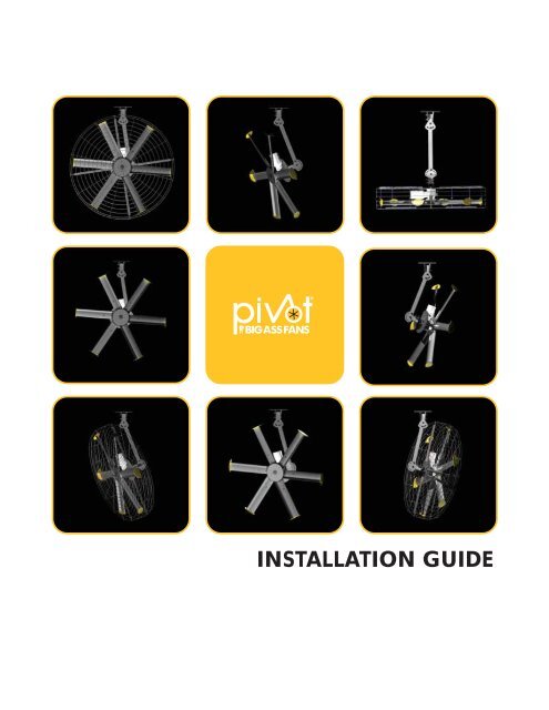
PIVOTContentsIntroduction Safety Instructions iiiii 1About <strong>Big</strong> <strong>Ass</strong> <strong>Fans</strong> 1About this Fan 1Pre-Installation Parts IncludedFan Diagram 5 6Pivot AngleMounting Structure:I-BeamMounting Structure:Bar Joists 81. Select Proper Angle Irons 9 11Hanging The Fan 15 155. Attach Pivot Joint 16 16Installing Airfoils 18 18 18Installing Cage 1. Attach Cage Bracket 19 19Pivoting the Fan Installing Guy Wires ®Electrical Installation Controller StorageConduit and Piping GuidelinesWWW.BIGASSFANS.COM ©2011 DELTA T CORP. DBA BIG ASS FAN ALL RIGHTS RESERVED
Parts includedNote: Drawings are not to scale.PIVOT3Beam Clip HardwareBalance/Pivot HardwareExtension Tube HardwareHardwareLower Yoke HardwareMain Fan Unit HardwareWinglet HardwareAirfoil Hardware(4) Guy Wire Hardware 1 ®MountingBracketsSpacerBalance JointPivot JointCenter Cap Cable Airfoils 1. <strong>Ass</strong> <strong>Fans</strong> recommends WWW.BIGASSFANS.COM ©2011 DELTA T CORP. DBA BIG ASS FAN ALL RIGHTS RESERVED
4Parts included (cont.)PIVOTCageSectionSectionCage HardwareCage Clip HardwareTools needed<strong>Big</strong> <strong>Ass</strong> Mechanical installationElectrical installationImportant weightsPart Weight Part Weight Airfoils 6-ft can cage WWW.BIGASSFANS.COM ©2011 DELTA T CORP. DBA BIG ASS FAN ALL RIGHTS RESERVED
Fan diagramPIVOT5A. Safety Cable. fan.B. Upper Yoke. C. Balance Joint. balance joint.D. Extension Tube. E. Pivot Joint. pivot joint.F. Lower Yoke. unit assembly to mounting assembly.G. Motor. See p. 1 for more information.H. Winglet. I. Airfoil. and effective air movement.J. Cage. WWW.BIGASSFANS.COM ©2011 DELTA T CORP. DBA BIG ASS FAN ALL RIGHTS RESERVED
6Preparing the work sitePIVOTMechanical installation <strong>Big</strong> <strong>Ass</strong> manual.I-BeamAngle Iron Safety requirementClearanceAirfoil heightFan spacingRadiant/IR heatersMinimum distancesElectrical installation The installation of a <strong>Big</strong> <strong>Ass</strong> The fan must be visible from its controller unless a suitable means of disconnect is used at the motor. AC supply feeds for a fan controller and the output/motor leads for the same fan may not share a conduit. WWW.BIGASSFANS.COM ©2011 DELTA T CORP. DBA BIG ASS FAN ALL RIGHTS RESERVED
Pivot anglePIVOT7 Pivot Angle Diagram¹2101201433470’’(178 cm)50’’(127 cm)80’’(203 cm)40’’(102 cm)23430’’(76 cm)20’’(51 cm)10’’ (25 cm)85”(216 cm)90’’(229 cm)90’’(229 cm)1. 1 ft from each measurement.WWW.BIGASSFANS.COM ©2011 DELTA T CORP. DBA BIG ASS FAN ALL RIGHTS RESERVED
PIVOT8 Mounting Structure: I-Beam<strong>Big</strong> <strong>Ass</strong> <strong>Fans</strong> can only be hung from an I-beam or bar joists. See the following page for bar joist mounting instructions.Consult a structural engineer for installation methods not covered in this manual.WARNING: The following instructions assume that the customer’s roof structure from which the fan will be hung is ofof the customer to verify that the roof structure is adequate for fan installation. <strong>Big</strong> <strong>Ass</strong> <strong>Fans</strong> recommends consulting astructural engineer prior to fan installation.CAUTION: It is not recommended to mount a <strong>Big</strong> <strong>Ass</strong> Fan from a fabricated I-beam.spacer are closer to one side than the other. Make sure this side is facing the I-beam.1. Attach upper yoke (to I-beam)40 ft·lb (54.2 N·m) socket.Beam Clip Hardware (BAF-Supplied):a. b. c. d. e. Small Upper YokeI-beamUpper yokemounting holesInner holesOuter holesouter holesmiddle holesinner holesUpper Yoke(top view)Large Upper YokeI-beamUpper yokemounting holesInner holesOuter holesSide ViewabdebcWWW.BIGASSFANS.COM ©2011 DELTA T CORP. DBA BIG ASS FAN ALL RIGHTS RESERVED
PIVOTMounting Structure: Bar JoistsWARNING: The following instructions assume that the customer’s roof structure from which the fan will be hung is ofsound construction, undamaged, and capable of supporting loads of the fan and its method of attachment. It is the soleresponsibility of the customer to verify that the roof structure is adequate for fan installation. <strong>Big</strong> <strong>Ass</strong> <strong>Fans</strong> recommendsconsulting a structural engineer prior to fan installation.WARNING: Never use beam clamps when mounting the fan to angle irons! Beam clamps are only intended for I-beaminstallations.CAUTION: Do not install the fan from a single purlin, truss, or bar joist.CAUTION: Unsupported angle iron spans should not exceed 12 ft (3.7 m).CAUTION: The angle irons must be fastened to the roof structure at each end.1. Select proper angle ironsNote: Angle irons and angle iron hardware are not included with the fan.Angle iron spanMinimum angle iron dimensionsNumber of angleirons needed Angle Iron Side View(see table for dimensions)HeightWidthThickness6’ (1.8m) or lessover 6’ (1.8m) - 8’ (2.4m)over 8’ (2.4m) - 12’ (3.7m)WWW.BIGASSFANS.COM ©2011 DELTA T CORP. DBA BIG ASS FAN ALL RIGHTS RESERVED
PIVOT10 2. Pre-drill angle ironsØ 9/16" (1.4cm)A1/2 A5 3/8” (13.7cm)distance between roofstructure mounting points3. Fasten angle irons together (if span is longer than 8 ft)If the angle iron span is 8 ft (2.4 m) or less, proceed to step 4a on the following page.of four angle irons.irons to each other and tighten the bolts to 40 ft·lb (54.2 N·m) Proceed to step 4b.Grade 8 Hardware (Customer-Supplied):a. b. c. cbbaSide ViewWWW.BIGASSFANS.COM ©2011 DELTA T CORP. DBA BIG ASS FAN ALL RIGHTS RESERVED
PIVOT114a. Fasten single angle irons to roof structure mounting pointsIf installation requires double angle irons (i.e., span is greater than 8 ft [2.4m]), proceed to step 4b. Do nottighten the hardware until the fan has been mounted to the angle irons.Proceed to step 5.Grade 8 Hardware (Customer-Supplied):a. b. c. d. Square Washera3”(7.6 cm)bØ 9/16”(1.4 cm)3”(7.6 cm)Thickness:1/4” (6 mm)cbdWWW.BIGASSFANS.COM ©2011 DELTA T CORP. DBA BIG ASS FAN ALL RIGHTS RESERVED
12PIVOT4b. Fasten double angle irons to roof structure mounting pointsDo not tighten the hardware until the fan has beenmounted to the angle irons.Grade 8 Hardware (Customer-Supplied):a. b. c. d. Square Washera3”(7.6 cm)bØ 9/16”(1.4 cm)3”(7.6 cm)Thickness:1/4” (6 mm)cbdWWW.BIGASSFANS.COM ©2011 DELTA T CORP. DBA BIG ASS FAN ALL RIGHTS RESERVED
PIVOT135. Attach upper yoke (to angle irons)Tighten the bolts to 40 ft·lb (54.2 N·m) all the bolts securing the angle irons to the roof structure to 40 ft·lb (54.2 N·m).Beam Clip Hardware (BAF-Supplied):a. b. c. 10 7/8" (27.6 cm) 15 5/8" (39.7 cm)Small Upper Yoke13 1/4’’ (33.7 cm) x9 5/8” (24.4 cm)Large Upper Yoke18’’ (45.7 cm) x9 5/8” (24.4 cm)Note: Dashed lines represent angle irons in the above illustrations.Side ViewabbcWWW.BIGASSFANS.COM ©2011 DELTA T CORP. DBA BIG ASS FAN ALL RIGHTS RESERVED
PIVOT14 Hanging the Fan1. Attach balance joint (to upper yoke)If the fan will not be pivoted, it is not necessary to install the balancejoint. Skip this step and proceed to Step 2b.Fasten the balance joint to the upper yoke (already attached to mountingfan is completely assembled.Balance/Pivot Hardware:a. b. c. cbDo not fully tighten bolts until fanis completely assembled!ba2a. Attach extension tube (to balance joint)fan is completely assembled.Proceed to Step 3.Extension Tube Hardware:a. b. c. cbbaDo not fully tighten bolts until fanis completely assembled!2b. Attach extension tube (to upper yoke)itself. Tighten the bolts to 40 ft·lb (54.2 N·m) using a socket.Extension Tube Hardware:a. b. c. cbbaWWW.BIGASSFANS.COM ©2011 DELTA T CORP. DBA BIG ASS FAN ALL RIGHTS RESERVED
PIVOT153. Secure upper safety cableThe safety cable is a crucial part of the fan and must be installed correctly. If you have questions, call CustomerService at 1-877-BIG-FANS for assistance.shackle should be on the topside of the I-beam or angle iron. Securely tighten the shackle.I-Beam MountShackleAngle Iron Mount4. Attach main fan unit (to lower yoke)CAUTION: When the fan is pivoted, the motor shouldnever be lower than the gearbox. This will protect themotor in case the gearbox leaks. Consider how the fanwill eventually be pivoted and position the lower yokeaccordingly.abTighten the bolts to 40 ft·lb (54.2 N·m) using aMain Fan Unit Hardware:a. b. c. bcWWW.BIGASSFANS.COM ©2011 DELTA T CORP. DBA BIG ASS FAN ALL RIGHTS RESERVED
16PIVOT5. Attach pivot jointIf the fan will not be pivoted, it is not necessary to install the pivotjoint. Skip this step and proceed to Step 6b.CAUTION: Install the bolts exactly as shown. Do not pivot the fanuntil it has been completely assembled.Balance/Pivot Hardware:a. b. c. abbcDo not fully tighten bolts until fan is completely assembled!6a. Attach lower yoke (to pivot joint)CAUTION: When the fan is pivoted, the motor should never be lower than the gearbox. This will protect the motor in casethe gearbox leaks. Consider how the fan will eventually be pivoted and position the motor accordingly.CAUTION: Install the bolts exactly as shown. Do not pivot the fan until it has been completely assembled.CAUTION: The motor frame is heavy. Use care when raising it.bolts.Proceed to Step 7.abLower Yoke Hardware:a. b. c. bcDo not fully tighten bolts until fan is completely assembled!WWW.BIGASSFANS.COM ©2011 DELTA T CORP. DBA BIG ASS FAN ALL RIGHTS RESERVED
PIVOT176b. Attach lower yoke (to extension tube)CAUTION: The motor frame is heavy. Use care when raising it.The lower yoke can only be attached to the extension tubethrough the topmost and bottommost holes on the lower yoke.Lower Yoke Hardware:a. b. c. cbba7. Attach center capSnap the center cap onto the bottom of the main fan unit.WWW.BIGASSFANS.COM ©2011 DELTA T CORP. DBA BIG ASS FAN ALL RIGHTS RESERVED
PIVOT18 Installing Airfoils1. Attach wingletsaWinglet Hardware:a. b. b2. Position airfoils and trimthe fan hub in one direction. Forcing an airfoil into place could damage it.3. Attach airfoil retainersHole B. Do not tighten the bolts until all the airfoil retainers have been attached!Tighten all the bolts on the airfoil retainers to Airfoil Hardware:a. b. c. aAirfoil RetainerbHole BHole AbcWWW.BIGASSFANS.COM ©2011 DELTA T CORP. DBA BIG ASS FAN ALL RIGHTS RESERVED
20PIVOT3. Attach lower cage sections (to upper cage)Cage Hardware:a. b. outer cageclipouter cageclipab4. Secure lower cage10 ft·lb(13.6 N·m).Cage and Cage Clip Hardware :a. b. c. d. abcdWWW.BIGASSFANS.COM ©2011 DELTA T CORP. DBA BIG ASS FAN ALL RIGHTS RESERVED
PIVOTPivoting the Fan211. Adjust pivot joint and lower yokeWARNING: Do not remove the bottom bolt of the pivot jointor the bottom bolt of the lower yoke.CAUTION: When the fan is pivoted, the motor should not belower than the gearbox (see pp. 16–17).WARNING: Before tightening the bolts, make sure the fanblades are clear of any obstructions including the safetycable and motor power cable.fan. Remove only one bolt at a time.40 ft·lb (54.2 N·m) usingsocket.AB2. Tighten bolts on upper yoke and balance jointcenter of gravity.Tighten the bolts to 40 ft·lb (54.2 N·m) socket.WWW.BIGASSFANS.COM ©2011 DELTA T CORP. DBA BIG ASS FAN ALL RIGHTS RESERVED
PIVOT22 Installing Guy WiresGuy wire installation is recommended if the fan’s extension tube is 4 ft (1.2 m) or longer, if the fan is pivoted, if the fan1. Attach eyebolt to motor frameGuy Wire Hardware:a. b. c. abbc2. Attach beam clampCAUTION: When taut, the guy wire must be clear of moving fanairfoils. Place the beam clamp accordingly.structure.Beam Clampaboutside of the beam clamp.Guy Wire Hardware:a. b. c. d. cd3. Route guy wire through Gripple ®GrippleNote: To back the guy wire out of the Gripple, insert 1/16 (1.5 mm) Allenwrench into the small hole on the Gripple.WWW.BIGASSFANS.COM ©2011 DELTA T CORP. DBA BIG ASS FAN ALL RIGHTS RESERVED
PIVOT234. Install remaining guy wiresCAUTION: Over-tightening the guy wires could throw the fan off balance.CAUTION: The guy wires should be spaced evenly around the fan and clear ofthe airfoils.Wire Rope Clip ® WWW.BIGASSFANS.COM ©2011 DELTA T CORP. DBA BIG ASS FAN ALL RIGHTS RESERVED
PIVOT24 Electrical Installationcause electric shock or damage the motor and the controller! Hazard of electrical shock!WARNING: The installation of a <strong>Big</strong> <strong>Ass</strong> and with any additional requirements set forth by the National Electric Code (NEC), ANSI/NFPA 70-2011, and all local codes.Code compliance is ultimately YOUR responsibility!WARNING: The fan controllers contain high voltage capacitors that take time to discharge after removal of mains supply.Before working on the fan controller, ensure isolation of mains supply from line inputs at the fan controller’s disconnect ifinstalled (L1, L2/N, and L3). Wait three (3) minutes for capacitors to discharge to safe voltage levels. Failure to do so mayresult in personal injury or death. Note: Darkened display LEDs are not an indication of safe voltage levels.CAUTION: It is the sole responsibility of the installer to verify the operating voltage of the fan system prior to installation! Itis also mandatory that the installer verify that airfoils, motor hub assemblies, and fan controllers are matched properly at thetime of installation, especially if multiple fan systems will be installed.CAUTION: An incorrectly installed controller can result in component damage or reduction in the fan’s life. Wiring orapplication errors such as under-sizing the controller, incorrect or inadequate AC supply, or excessive ambient temperaturesmay result in a malfunction of the fan system. Verify correct voltage, phase, and horsepower before beginning installation!WARNING: Exercise caution and common sense when powering the fan. Do not connect the fan to a damaged or hazardouspower source. Do not attempt to resolve electrical malfunctions or failures on your own. Contact <strong>Big</strong> <strong>Ass</strong> <strong>Fans</strong> at 1-877-BIG-FANS if you have any questions regarding the electrical installation of this fan.CAUTION: For use with <strong>Big</strong> <strong>Ass</strong> <strong>Fans</strong>-supplied variable frequency drive only. Not for use with other speed control devices!CAUTION: Shielded cable, if applicable, must be landed on the motor’s ground terminal!CAUTION: To avoid a short circuit, be very careful not to get metal chips in the controller!CAUTION: The <strong>Big</strong> <strong>Ass</strong> <strong>Fans</strong> product warranty will not cover equipment damage or failure that is caused by improperinstallation.CAUTION: The following information is merely a guide for proper installation. The <strong>Big</strong> <strong>Ass</strong> <strong>Fans</strong> Company cannot assumeresponsibility for the compliance or the non-compliance to any code, national, local, or otherwise for the proper installation ofthese fan controllers, fans, or associated equipment. A hazard of personal injury and/or equipment damage exists if codes areignored during installationElectrical installation overviewcould result. This guide is merely a recommendation of proper installation. Adhering to national and local electric codes is yourController storagethe internal DC bus capacitors.WWW.BIGASSFANS.COM ©2011 DELTA T CORP. DBA BIG ASS FAN ALL RIGHTS RESERVED
Power requirements for fan controllersPIVOT25<strong>Ass</strong> controllers arePhase Recommended Nominal Maximum cont.Rated Nominal AC lineinput minimum feeder output output currentHP (kW) input voltage() size voltage, 3 1 (as programmed) 2 1 1 15A 1.6A1. This value may vary due to input voltage conditions.Mounting the wall controller Note: Multiple fan controllers are available as a special order only. Please contact Customer Service at 1-877-BIG-FANS for moreinformation.6.25” (159 mm)5.95” (151 mm)WARNINGDO NOT USE THISDISCONNECT TOSTART AND STOP THEFAN. PERMANENTDAMAGE WILLRESULT!SCA ME10.9” (277 mm)9.5” (241 mm)AUTOFWDREVRUNMR FSTOP1 2 5 6 25 4 1113A13B13C 14 30 16 17PEU/T1 V/T2 W/T3L1L1 L2 L2 L35.51” (140 mm)L3WWW.BIGASSFANS.COM ©2011 DELTA T CORP. DBA BIG ASS FAN ALL RIGHTS RESERVED
26Input power conditioningPIVOT <strong>Ass</strong> Conduit and piping guidelinesCAUTION: The presence of foreign signals on a drive’s output wiring greatly reduces the controller’s ability to controlFailure to do so may result in nuisance tripping and/or premature equipment failure. Sources of foreign signals that couldCAUTION: Recommendations for fan controller output/motor lead routing deem some conventional wiring practiceshowever, due to the nature of the <strong>Big</strong> <strong>Ass</strong> Fan system, there are additional requirements that must be met to ensureproper operation.<strong>Ass</strong> <strong>Fans</strong>. Due to<strong>Ass</strong> Controller AC supply AC supply feeds for a fan controller and output/motor leads for the same fan controller cannot share a conduit. shock due to induced voltages. Output/motor leads for a fan controller and AC supply feeds for the same fan controller cannot share a conduit. additional fan controllers. of electric shock due to induced voltages.Power wiring guidelinesIn order to satisfy some code requirements, it may be necessary to install a manual disconnect at the fan motoretc.) regarding wire types, conductor sizes, branch circuit protection, and disconnecting devices.WARNING: To avoid a possible shock hazard and/or nuisance tripping caused by induced voltages, unused wires in theconduit must be grounded at both ends. For the same reason, fan controller output wires should not share a conduit withanother fan controllers output leads, or other power circuits (lighting, motors, etc.).varieties must be avoided. Do not use solid core cable of any size or insulation class for motor wiring. Use of such typesof cabling may result in nuisance tripping or premature equipment failure.For many installations, unshielded cable is adequateif it can be separated from sensitive circuits. WWW.BIGASSFANS.COM ©2011 DELTA T CORP. DBA BIG ASS FAN ALL RIGHTS RESERVED
Power wiring guidelines (cont.)PIVOT27Acceptable unshielded typeslimits are provided. Do not use THHN or similarly coated wire in wet areas.of 15 mils and should not have large variations in insulation concentricity.Acceptable shielded typesLocation Rating / Type DescriptionStandardStandard coverage Maximum cable lengthsOutput disconnectsstopping the motor cannot be used.Recommended wire size14AWG applies to motor leads only. Grounding<strong>Ass</strong> <strong>Fans</strong>. Due to highthe recommendations made in this section. Motor groundShielded motor cable terminationsWWW.BIGASSFANS.COM ©2011 DELTA T CORP. DBA BIG ASS FAN ALL RIGHTS RESERVED
PIVOT28Installing the Electronic Programming Module (EPM)If hanging multiple fans, ensure to install the exact EPM included in each fan’s packaging. EPMs are notinterchangeable!CAUTION: Install the EPM prior to applying power to the fan controller!must be installed prior toTo install the EPM, Note: The EPM can only be inserted one way. Do not force it!WARNINGDO NOT USE THISDISCONNECT TOSTART AND STOP THEFAN. PERMANENTDAMAGE WILLRESULT!SCA MEAUTOFWDREVRUNElectronicProgrammingModuleMRFSTOP1 2 5 6 25 4 1113A13B13C 14 30 16 17L1U/T1 V/T2 W/T3PEL1 L2 L2 L3L3WWW.BIGASSFANS.COM ©2011 DELTA T CORP. DBA BIG ASS FAN ALL RIGHTS RESERVED
PIVOTWiring: Early Suppression Fast Response (ESFR)WARNING: Wait three minutes after disconnecting before servicing!should perform the installation.ATTENTION: If installing the fan in the United States, the fan must be installed per the following National Fire Protection<strong>Ass</strong>ociation (NFPA) guidelines: The fan must be centered approximately between four adjacent sprinklers. Terminals 4 & 13Afor ESFR RelayAUTOFWD1 2 5 6 25 4 1113A13B13C 14 30 16 17REVRUNMRFSTOPL1U/T1 V/T2 W/T3PEL1 L2 L2 L3L3From Main FACP orNAC Box if Applicable.PAM-SDRelay Coil/Contact DetailsRelay is mounted to thebackside of the access cover.White (X2)Red (X2)(-)(+)CNCNOCoil: 20-32VDC @ 20mABlueYellowOrangeWWW.BIGASSFANS.COM ©2011 DELTA T CORP. DBA BIG ASS FAN ALL RIGHTS RESERVED
30PIVOTWiring: 100–125V/200–250V single-phase fan controllersWARNING: Wait three minutes after disconnecting before servicing!should perform the installation.Note: This fan controller does not contain fusing!Power must be supplied to this controller viaa dedicated circuit breaker or properly fuseddisconnect!1 2 5 6 25 4 1113A13B13C 14 30 16 17L1U/T1 V/T2 W/T3PEL2L1 L2 L3NAC Input Wiring2W plus GNDMotor Output Wiring3W plus GNDNote: This fan controller does not contain fusing!Power must be supplied to this controller viaa dedicated circuit breaker or properly fuseddisconnect!1 2 5 6 25 4 11 13A13B13C14 14 3016 17L1U/T1 V/T2 W/T3PEL1 L2 L2 L3NAC Input Wiring2W plus GNDMotor Output Wiring3W plus GNDWWW.BIGASSFANS.COM ©2011 DELTA T CORP. DBA BIG ASS FAN ALL RIGHTS RESERVED
PIVOTWiring: 200–250V three-phase fan controllers31WARNING: Wait three minutes after disconnecting before servicing!should perform the installation.fan controller.Note: This fan controller does not contain fusing!Power must be supplied to this controller viaa dedicated circuit breaker or properly fuseddisconnect!1 2 5 6 25 4 1113A13B13C 14 30 16 17L1U/T1 V/T2 W/T3PEL2L1 L2 L3L3AC Input Wiring3W plus GNDMotor Output Wiring3W plus GNDthis fan controller.Note: This fan controller does not contain fusing!Power must be supplied to this controller via adedicated circuit breaker or properly fused disconnect!1 2 5 6 25 4 1113A13B13C 14 30 16 17U/T1 V/T2 W/T3L1PEL1 L2L2L3L3AC Input Wiring2W plus GNDMotor Output Wiring3W plus GNDWWW.BIGASSFANS.COM ©2011 DELTA T CORP. DBA BIG ASS FAN ALL RIGHTS RESERVED
32PIVOTWiring: 400–480V & 575–600V three-phase fan controllersWARNING: Wait three minutes after disconnecting before servicing!should perform the installation.Wiring for 400–Note: This fan controller does not contain fusing!Power must be supplied to this controller viaa dedicated circuit breaker or properly fuseddisconnect!1 2 5 6 25 4 1113A13B13C 14 30 16 17U/T1 V/T2 W/T3PEL1L2L1 L2 L3L3AC Input Wiring3W plus GNDMotor Output Wiring3W plus GNDWiring for 575–fan controller.Note: This fan controller does not contain fusing!Power must be supplied to this controller via adedicated circuit breaker or properly fused disconnect!1 2 5 6 25 4 1113A13B13C 14 30 16 17L1U/T1 V/T2 W/T3PEL2L1 L2 L3L3AC Input Wiring3W plus GNDMotor Output Wiring3W plus GNDWWW.BIGASSFANS.COM ©2011 DELTA T CORP. DBA BIG ASS FAN ALL RIGHTS RESERVED
Daisy ChainingPIVOT33WARNING: Wait three minutes after disconnecting before servicing! the fan controllers together ensures minimal signal loss of command signals in larger multi-fan systems.<strong>Ass</strong>ertion Level Switch (ALSW)signal and start stop signal to share that common. The <strong>Ass</strong>ertion Level Switch above terminal 4 must be switched from (+) to ( - )on all downstream fan controllers for proper daisy chaining operation prior to powerup, parameter changes and operation.Parameter changes (for downstream controllers)ParameterDescriptionRelay Output FunctionParameterDescription<strong>Ass</strong>ertion LevelTB-30 OutputTB-30 Scaling FrequencySpeed at Max SignalStart Control Sourcefor Terminal Strip.Standard Reference SourceNote: Depending on the AWG and distance of the low voltage wiring, the downstream fans may run slightly slower than the leading fan.If this occurs, P161 Speed at Max Signal can be used to introduce a minor command reference overshoot to compensate for the analoguntil the fan’s output frequency matches that of the lead fan.#17 = N.O. Relay Output#4 = Digital Common*#17 = N.O. Relay Output#2 = Analog Common#16 = N.O. Relay Output#30 = 0–10VDC Output#5 = 0–10VDC Input#2 = Analog Common#1 = Run/Stop Input#16 = N.O. Relay Output#30 = 0–10VDC Output1 2 5 6 25 4 1113A13B13C1413B 13C 14 30 16 171 2 5 6 25 4 11 13A13B13C14 13B 13C 14 30 16 17U/T1 V/T2 W/T3PEL1 L2 L3U/T1 V/T2 W/T3PEL1 L2 L3Terminals 2 and 16 shall all be tied togetheron the first fan controller.Terminals 2, 4 and 16 shall all be tiedtogether on all downstream fan controllers.3 conductor shielded cable minimum 20AWG Stranded(provided by installer) Recommended Maximum distance0–10VDC and Start/Stopout to next downstreamcontrollerWWW.BIGASSFANS.COM ©2011 DELTA T CORP. DBA BIG ASS FAN ALL RIGHTS RESERVED
PIVOT34 rotation. Note: Swapping leads to reverse rotation is done only on the output side of the drive.Low VoltageHigh VoltageU2T4V2T5W2T6U2T4V2T5W2T6U5T7V5T8W5T9U5T7V5T8W5T9U1T1V1T2W1T3U1T1V1T2W1T3VAC from VFDBLUEREDBLACKGREEN W/ YELLOW TRACERVAC from VFDYELORANGEBROWNGREEN W/ YELLOW TRACERLow V oltageHigh VoltageJumper bars aremotorWWW.BIGASSFANS.COM ©2011 DELTA T CORP. DBA BIG ASS FAN ALL RIGHTS RESERVED
Operating the fan controllerPIVOT35WARNING: The following startup procedures apply to standard model controllers. Procedures may vary depending oninstallation options and system automation. The installer should verify proper wiring, terminations, and proper voltageStarting and stopping the fanAUTOFWDRUNfunctions. To start the fan,To stopthe fan, press the red STOP button.REVMR FRUNSTOPDrive Idle/Stopped ScreenSTOPAdjusting fan speedTo adjust fan speed,speed until the button is released.AUTOMFWDREVR FRUNSTOPR FthenMReversing direction of fan rotationindicating the pending change.Fan Speed Percentage Display(73.5% running FWD)AUTOFWDREVRUNMRFSTOPTypical Fault Message Display(Incoming Line Over-Voltage shown)months. If the fan is not rotating in this direction, press the Direction button, and then press the Memory/Enter button. During theWWW.BIGASSFANS.COM ©2011 DELTA T CORP. DBA BIG ASS FAN ALL RIGHTS RESERVED
PIVOT36 Preventive Maintenanceappliance from the power supply before servicing.WARNING: Before servicing or cleaning the fan, switch off power at service panel and lock the service disconnectingmeans to prevent power from being switched on accidentally. When the service disconnecting means cannot be locked,securely fasten a prominent warning device (such as a tag) to the service panel.WARNING: When service or replacement of a component in the fan requires the removal or disconnection of a safetydevice, the safety device is to be reinstalled or remounted as previously installed.Annual preventive maintenanceNote: Actual installation setup may differ from picture.1. securely tightened. I 5. airfoils are secured to one another by airfoil retainers.6. 8. General preventive maintenance gentle cleaner or degreasing agent to polish the airfoils. Do ® Check all fan controller connections and tighten as needed.and outside of the controller. WARNING: Do not operate a fan with missing ordamaged components! Please contact Customer Serviceat 1-877-BIG-FANS.2134 567WWW.BIGASSFANS.COM ©2011 DELTA T CORP. DBA BIG ASS FAN ALL RIGHTS RESERVED
Annual Maintenance ChecklistFan Model: Fan Model: Fan Model:Serial #: Serial #: Serial #:Location: Location: Location:Date Initials Date Initials Date Initials
PIVOTTroubleshootingWARNING: When servicing or replacement of a component in the fan requires the removal or disconnection of a safetydevice, the safety device is to be reinstalled or remounted as previously installed.power supply before servicing.WARNING: TO REDUCE THE RISK OF FIRE, ELECTRIC SHOCK, OR INJURY TO PERSONS, OBSERVE THE FOLLOWING:a) Use this fan only in the manner intended by the manufacturer. If you have questions, contact the manufacturer.b) Before servicing or cleaning the fan, switch power off at service panel and lock the service disconnecting means toprevent power from being switched on accidentally. When the service disconnecting means cannot be locked, securelyfasten a prominent warning device, such as a tag, to the service panel.support.SymptomThe fan is turning in the wrong direction.A popping noise is coming from the fan.Airfoil noise comes from airfoils that areThe fan will not start.The fan controller generates radiofrequency noise (RF).Fan controllers generate RF noise in manyThe motor makes noise when fan speed isincreased.be an indicator of a stall condition.Possible solution(s)button on the controller.<strong>Ass</strong> Note: Some motor, gearbox, or drive noise is to be expected and is normal.WWW.BIGASSFANS.COM ©2011 DELTA T CORP. DBA BIG ASS FAN ALL RIGHTS RESERVED
PIVOT40 Warranty Return InstructionsCongratulations on your purchase of a <strong>Big</strong> <strong>Ass</strong> Replacement of products under warranty acknowledgment & return instructionsreceipt of the replacement item.Instructions for Returning the Original Item1. <strong>Big</strong> <strong>Ass</strong> Fan Company 5. pickup location.<strong>Big</strong> <strong>Ass</strong> Fan CompanyWWW.BIGASSFANS.COM ©2011 DELTA T CORP. DBA BIG ASS FAN ALL RIGHTS RESERVED
Warranty claim form instructionsPIVOT411. Note: an RMA# by <strong>Big</strong> <strong>Ass</strong> Fan Company Customer Service. Note at 800 Winchester Road, Lexington, KY 40505.a. <strong>Ass</strong>b. the packing list and a return address label included inside this packaging to return the original part. If the original packaging andNote: The RMA# must appear on the outside of the box being returned. Items without an RMA# will not be accepted.c. d. WWW.BIGASSFANS.COM ©2011 DELTA T CORP. DBA BIG ASS FAN ALL RIGHTS RESERVED
Warranty Claim Formassfans.comName (print):Signature:Company:Shipping Address:City/State/ZIP:Phone:Items Returned:Fax:Date ofPurchase:Reason(s) for Returning Item<strong>Ass</strong> Fan Company Customer ServiceDepartment. The RMA# must appear on the outside of the box being returned. Items without an RMA# will not be accepted.Date Replacement PartsShould Be Shipped (if known):(to be completed by <strong>Big</strong> <strong>Ass</strong> Acknowledged By:Date:RMA#:Authorized Truck Line(s):
Responsibility Agreementassfans.comTo: <strong>Big</strong> <strong>Ass</strong> Fan Company<strong>Ass</strong><strong>Fans</strong> (“<strong>Big</strong> <strong>Ass</strong> merchandise should be replaced at no cost under <strong>Big</strong> <strong>Ass</strong> The undersigned further agrees that if <strong>Big</strong> <strong>Ass</strong> <strong>Ass</strong> The undersigned agrees to ship to <strong>Big</strong> <strong>Ass</strong> merchandise replaced by <strong>Big</strong> <strong>Ass</strong> the receipt of the any replacements.The undersigned further agrees that if said replaced merchandise has not been shipped to <strong>Big</strong> <strong>Ass</strong> <strong>Ass</strong> Signed:Title:For:Date:
Check-In Procedure(for <strong>Big</strong> <strong>Ass</strong> assfans.comATTENTION: These items must be completed prior to any additional installation crew members entering jobsite or anyinstallation material being unloaded.Date:Company:Address:Job Name:Purchase Order No.:City/State/ZIP:Contact Name:Phone:E-mail:**SEE THE FOLLOWING PAGE FOR NFPA 13 REGULATIONS**Safety Rules and Regulations listed:Additional comments:
Check-In Procedure (cont.)(for <strong>Big</strong> <strong>Ass</strong> National Fire Protection <strong>Ass</strong>ociation Standard I<strong>Ass</strong> please provide understanding and agreement of the installation to be completed.Customer Signature:Printed Name:Date:Contractor Signature:Printed Name:Date:<strong>Ass</strong><strong>Fans</strong>.
Close-Out Procedure(for <strong>Big</strong> <strong>Ass</strong> assfans.comDate:Company:Job Name:Address:Purchase Order No.:City/State/ZIP:Contact Name:Phone:E-mail:at check-in.Additional comments:
Close-Out Procedure (cont.)(for <strong>Big</strong> <strong>Ass</strong> National Fire Protection <strong>Ass</strong>ociation Standard NOTE: The customer’s initials are required as acknowledgement for the following instances:Return Trip Required – Additional Charges Apply (Customer not Ready/Lift Issues)Work Completed Outside Scope of Work (if applicable)Customer Understands and Approves Additional Charges As Explained in amount of $Other (Please Explain Below)(if applicable)I<strong>Ass</strong> please provide understanding and agreement of the installation to be completed.Customer Signature:Printed Name:Date:Contractor Signature:Printed Name:Date:<strong>Ass</strong><strong>Fans</strong>.
1001010801Rev. H2348 Innovation Drive Lexington, KY 40511 1-877-BIG-FANS