Isis Installation Guide - Big Ass Fans
Isis Installation Guide - Big Ass Fans
Isis Installation Guide - Big Ass Fans

Create successful ePaper yourself
Turn your PDF publications into a flip-book with our unique Google optimized e-Paper software.
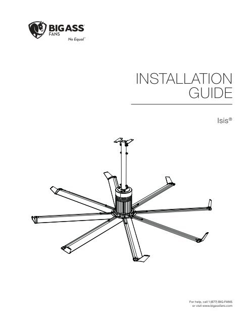
INSTALLATION<br />
GUIDE<br />
<strong>Isis</strong> ®<br />
For help, call 1 (877) BIG-FANS<br />
or visit www.bigassfans.com
<strong>Isis</strong> ®<br />
<strong>Installation</strong> Checklist<br />
Did a structural engineer approve the mounting structure? See page 7 for <strong>Big</strong> <strong>Ass</strong> <strong>Fans</strong>-approved<br />
mounting structures.<br />
<br />
Will the fan be installed so that the airfoils have at least 2 ft (0.61 m) of clearance from<br />
obstructions?<br />
Will the fan be installed so that it is not subjected to high winds such as from a Heating,<br />
Ventilating, and Air Conditioning (HVAC) system or near a large garage door? If the fan is<br />
mounted at the same level or higher than a diffuser, the winglets or airfoil tips must be at a distance<br />
that is at least 1x the measure of the fan’s diameter. If the fan is mounted at the same height or below<br />
a diffuser, the winglets or airfoil tips must be at a distance that is at least 2x the measure of the fan’s<br />
diameter.<br />
Will the fan be mounted where it will not come into direct contact with water? The fan should not<br />
be mounted where it will come into direct contact with water unless it is labeled, “Suitable for use in wet<br />
locations.”<br />
Will the distance between multiple fans be at least 2.5x the fans’ diameter when measured from<br />
the centers of the fans?<br />
If you ordered multiple fans, did you keep the parts of each fan together?<br />
What type of circuit does your building structure have, 3-wire or 2-wire? <strong>Isis</strong> ® 120 V is shipped<br />
with a controller that is compatible with 3-wire circuits. If your building structure includes a 2-wire circuit,<br />
the Limited Access Controller and Remote must be installed with the fan. If you require the Limited<br />
Access Controller and did not note it at the time of order, contact Customer Service.<br />
Customer Service: 1-877-BIG-FANS<br />
(International: +1 859 233 1271)<br />
WWW.BIGASSFANS.COM ©2014 DELTA T CORP. DBA BIG ASS FAN CO. ALL RIGHTS RESERVED
<strong>Isis</strong> ®<br />
<strong>Installation</strong> <strong>Guide</strong><br />
<strong>Isis</strong> ®<br />
i<br />
<strong>Installation</strong> <strong>Guide</strong>:<br />
Jan. 2014<br />
Rev. B<br />
3187235<br />
Conforms to ANSI/UL STD 507–Electric <strong>Fans</strong><br />
<br />
This product was manufactured in a plant whose<br />
<br />
conformity with ISO 9001:2008.<br />
Contact Information<br />
Manufacturing<br />
2425 Merchant Street<br />
Lexington, KY 40511<br />
1-877-BIG-FANS<br />
assfans.com<br />
Customer Service<br />
<br />
Lexington, KY 40511<br />
1-877-BIG-FANS<br />
<br />
assfans.com<br />
Warranty Returns<br />
800 Winchester Road<br />
Lexington, KY 40505<br />
1-877-BIG-FANS<br />
assfans.com<br />
<br />
Unit 4, 5 McPhall Road<br />
Coomera QLD 4209<br />
(07) 550 0690<br />
assfans.com.au<br />
EU Authorized Representative<br />
A L U R A G R O U P<br />
Zwolsestraat 156<br />
2587 WB The Hague,<br />
The Netherlands<br />
<br />
<br />
reproduced or translated into a different language without the prior written consent of <strong>Big</strong> <strong>Ass</strong> <br />
assfans.com.<br />
WWW.BIGASSFANS.COM ©2014 DELTA T CORP. DBA BIG ASS FAN CO. ALL RIGHTS RESERVED
ii<br />
<strong>Isis</strong> ®<br />
IMPORTANT SAFETY INSTRUCTIONS<br />
READ AND SAVE THESE INSTRUCTIONS<br />
TO REDUCE THE RISK OF FIRE, ELECTRIC SHOCK, OR INJURY TO PERSONS, OBSERVE THE FOLLOWING:<br />
<br />
and standards.<br />
CAUTION: When cutting or drilling into wall or ceiling, do not damage electrical wiring and other hidden utilities.<br />
CAUTION: Use this unit only in the manner intended by the manufacturer. If you have questions, contact the manufacturer.<br />
WARNING: Before servicing or cleaning unit, switch power off at service panel and lock the service disconnecting means to<br />
prevent power from being switched on accidentally. When the service disconnecting means cannot be locked, securely fasten<br />
a prominent warning device, such as a tag, to the service panel.<br />
CAUTION: The installation of a <strong>Big</strong> <strong>Ass</strong> <br />
<br />
Code compliance is ultimately YOUR responsibility!<br />
CAUTION: Exercise caution and common sense when powering the fan. Do not connect the fan to a damaged or hazardous<br />
power source. Do not attempt to resolve electrical malfunctions or failures on your own. Contact <strong>Big</strong> <strong>Ass</strong> <strong>Fans</strong> if you have any<br />
questions regarding the electrical installation of this fan.<br />
<strong>Ass</strong> <strong>Fans</strong> must be installed with <strong>Big</strong> <strong>Ass</strong><br />
<br />
substituted.<br />
CAUTION: When service or replacement of a component in the fan requires the removal or disconnection of a safety device,<br />
the safety device is to be reinstalled or remounted as previously installed.<br />
<br />
the power supply before servicing.<br />
<br />
rotating airfoils.<br />
WARNING: Stay alert, watch what you are doing, and use common sense when installing fans. Do not install fans if tired<br />
<br />
<br />
CAUTION: The installation of this fan requires the use of some power tools. Follow the safety procedures found in the owner’s<br />
manual for each of these tools and do not use them for purposes other than those intended by the manufacturer.<br />
CAUTION: The <strong>Big</strong> <strong>Ass</strong> <strong>Fans</strong> product warranty will not cover equipment damage or failure that is caused by improper<br />
installation.<br />
Leave this installation guide with the owner of the fan after installation is complete.<br />
CAUTION: Do NOT install the fan where it may come into direct contact with water unless the fan is labeled, “Suitable for use<br />
in wet locations.”<br />
ATTENTION: If installing the fan in the United States, the fan must be installed per the following National Fire Protection<br />
<br />
<br />
<br />
<br />
WWW.BIGASSFANS.COM ©2014 DELTA T CORP. DBA BIG ASS FAN CO. ALL RIGHTS RESERVED
<strong>Isis</strong> ®<br />
Reference <strong>Guide</strong><br />
The following is intended as a reference guide. See the referenced pages for complete fan installation and operating instructions.<br />
Mounting the fan<br />
If mounting to bar joists, see Mounting Structure:<br />
Bar Joists on page 9.<br />
If mounting to a wood frame structure, see<br />
Mounting Structure: Wood Frame on page 14.<br />
If mounting to a solid beam, see Mounting<br />
Structure: Solid Beam on page 18.<br />
Wiring the controller and fan<br />
See Electrical <strong>Installation</strong> on page 27.<br />
Mounting the controller<br />
See Mounting the Wall Controller on page 32.<br />
Operating the fan<br />
See Fan Operation on page 33.<br />
For alternative mounting methods, see page 4.<br />
Hanging the fan<br />
See Hanging the Fan on page 20.<br />
Airfoil installation<br />
See Installing Airfoils on page 25.<br />
Winglet installation<br />
See Installing Airfoils on page 25.<br />
*Winglets are standard. Airfoil tips are<br />
available as an option.<br />
WWW.BIGASSFANS.COM ©2013 DELTA T CORP. DBA BIG ASS FAN CO. ALL RIGHTS RESERVED
<strong>Isis</strong> ®<br />
Reference <strong>Guide</strong>: Mounting<br />
The following is intended as a reference guide for <strong>Isis</strong> ® fan mounting methods. See the referenced pages for complete fan installation and operating instructions. Consult a structural<br />
engineer to determine which mounting method best suits your building structure. To order optional mounting kits, see the Optional Parts Order Form (page 43).<br />
Bar Joists<br />
Wood Frame Structures<br />
I-Beam Z-Purlins Solid Beam<br />
See page 9 for mounting<br />
instructions.<br />
See page 14 for mounting<br />
instructions.<br />
See complete instructions<br />
included with the I-Beam<br />
Adapter <strong>Installation</strong> Kit.<br />
See complete instructions<br />
included with the Z-Purlin<br />
<strong>Installation</strong> Kit.<br />
See page 18 for mounting<br />
instructions.<br />
WWW.BIGASSFANS.COM ©2013 DELTA T CORP. DBA BIG ASS FAN CO. ALL RIGHTS RESERVED
<strong>Isis</strong> ®<br />
Contents<br />
General Information<br />
Important Safety Information ii<br />
Reference <strong>Guide</strong><br />
Reference <strong>Guide</strong> (Mounting)<br />
Introduction<br />
Thank You 1<br />
About <strong>Big</strong> <strong>Ass</strong> <strong>Fans</strong> 1<br />
About this Fan 1<br />
Pre-<strong>Installation</strong><br />
What’s in the Box 2<br />
Parts Included 3<br />
Alternative Mounting Methods 4<br />
Tools Needed 5<br />
Fan Diagram 6<br />
Preparing the Work Site 7<br />
iii<br />
iv<br />
Mounting Structure:<br />
Bar Joists<br />
Mounting Structure:<br />
Wood Frame<br />
Mounting Structure:<br />
Solid Beam<br />
1. Select Proper Angle Irons 9<br />
2. Pre-drill Angle Irons 10<br />
3. Secure Angle Irons (span is longer than 8 ft) 10<br />
4a. Fasten Single Angle Irons to Roof Structure Mounting Points 11<br />
4b. Fasten Double Angle Irons to Roof Structure Mounting Points 12<br />
5. Attach Upper Mount (to Angle Irons) 13<br />
1. Identify Mounting Location 14<br />
2a. Fasten Brackets (to Vaulted Ceiling Beams) 14<br />
2b. Fasten Brackets (to Floor Joists) 15<br />
2c. Fasten Brackets (to Ceiling Joists) 15<br />
3. Attach Upper Mount (to Wood Framing Channels) 16<br />
4. Fasten Wood Framing Channels (to Brackets) 17<br />
1. Pre-drill Suitable Mounting Structure 18<br />
2. Determine Bracket Orientation 18<br />
3a. Attach L-Brackets (to Mounting Structure) 19<br />
3b. Attach L-Brackets (to Mounting Structure with Safety Clips) 19<br />
4. Attach Upper Mount (to L-Brackets) 19<br />
Hanging the Fan<br />
1. Attach Extension Tube (to Upper Mount) 20<br />
2a. Secure Safety Cable (to Angle Irons) 20<br />
2b. Secure Safety Cable (to Wood Frame) 20<br />
2c. Secure Safety Cable (to Solid Beam) 21<br />
2d. Secure Safety Cable (to Solid Beam with Safety Clips) 21<br />
3. Attach Main Fan Unit (to Extension Tube) 21<br />
Installing Guy Wires<br />
1. Attach Guy Wire Clamps 22<br />
2. Attach Locking Carabiners to Guy Wire Clamps 23<br />
3a. Attach Beam Clamp (Bar Joist Mounting) 23<br />
3b. Attach Eyebolt (Wood Frame Mounting) 23<br />
4. Route Guy Wire through Gripple ® 24<br />
5. Install Three Remaining Guy Wires 24<br />
Installing Airfoils<br />
1. Attach Winglets or Airfoil Tips (to Airfoils) 25<br />
2. Position Airfoils 25<br />
3. Attach Airfoils (to Main Fan Unit) 26<br />
Electrical <strong>Installation</strong><br />
Electrical <strong>Installation</strong> Safety 27<br />
Power Requirements 27<br />
Wiring: Single Fan Application (120 V <strong>Isis</strong> ® ) 28<br />
Wiring: Multi-Fan Application (120 V <strong>Isis</strong>) 29<br />
Wiring the Fan (240 V, 50 Hz <strong>Isis</strong>) 30<br />
Wiring the Fan (240 V, 50/60 Hz <strong>Isis</strong> 31<br />
Mounting the Wall Controller (120 V <strong>Isis</strong>) 32<br />
Mounting the Wall Controller (240 V, 50 Hz <strong>Isis</strong>) 32<br />
Mounting the Wall Controller (240 V, 50/60 Hz <strong>Isis</strong>) 32<br />
WWW.BIGASSFANS.COM ©2014 DELTA T CORP. DBA BIG ASS FAN CO. ALL RIGHTS RESERVED
<strong>Isis</strong> ®<br />
Contents<br />
Fan Operation<br />
120 V <strong>Isis</strong> ® 33<br />
240 V, 50 Hz <strong>Isis</strong> 33<br />
240 V, 50/60 Hz <strong>Isis</strong> 33<br />
Changing the Fan Direction 34<br />
Alternative Wiring<br />
Methods (120 V <strong>Isis</strong> ® )<br />
Preventive Maintenance<br />
Limited Access Application 35<br />
Limited Access Fan Controller and Controller Remote Operation 36<br />
3-Way Single Fan Application 37<br />
Annual Preventive Maintenance 38<br />
General Preventive Maintenance 38<br />
Troubleshooting<br />
General Troubleshooting 39<br />
Electrical Troubleshooting 39<br />
Replacing Fuses 40<br />
Annual Maintenance<br />
Checklist<br />
Optional Parts Order<br />
Form<br />
Warranty Return<br />
Instructions<br />
<strong>Big</strong> <strong>Ass</strong> <br />
Installers<br />
Annual Maintenance Checklist 41<br />
Optional Parts Order Form 43<br />
Acknowledgment & Return Instructions 45<br />
Warranty Claim Form Instructions 46<br />
Warranty Claim Form 47<br />
Responsibility Agreement 48<br />
Check-In Procedure 49<br />
Close-Out Procedure 51<br />
WWW.BIGASSFANS.COM ©2014 DELTA T CORP. DBA BIG ASS FAN CO. ALL RIGHTS RESERVED
About this fan<br />
<strong>Isis</strong> ®<br />
Introduction<br />
Thank you and congratulations on your purchase of a <strong>Big</strong> <strong>Ass</strong> <br />
warm in the winter. The revolutionary design of our fans combines the best of both form and function to bring power performance and a<br />
sleek look to any setting. More importantly, you have purchased a product that is backed by extensive research, thorough testing, and<br />
<br />
www.bigassfans.com.<br />
Who we are and what we do<br />
<strong>Big</strong> <strong>Ass</strong> <br />
located in beautiful Lexington, KY, we research, design, and manufacture the most effective air movement solutions on the market.<br />
<br />
customers satisfy their needs, and a strong sense of corporate responsibility to the community, <strong>Big</strong> <strong>Ass</strong> <br />
business is done.<br />
<strong>Isis</strong> ® is shipped with either a 110–125 VAC motor or a 200–240 VAC motor. The fan’s voltage is marked on the fan packaging and on<br />
the label on top of the main fan unit. The voltage cannot be changed during installation. Ensure your fan is the correct voltage prior<br />
to beginning installation.<br />
110–125 VAC <strong>Isis</strong><br />
Fan diameter<br />
Input power<br />
Required<br />
circuit size<br />
Full load<br />
amps<br />
Max<br />
RPM<br />
Airfoil length<br />
8 ft (2.44 m) 110–125 VAC, 60 Hz 10 A 3.9 120 40” (101 cm)<br />
10 ft (3.04 m) 110–125 VAC, 60 Hz 10 A 3.9 80 52” (132 cm)<br />
12 ft (3.70 m) 110–125 VAC, 60 Hz 10 A 3.9 55 64” (162 cm)<br />
200–240 VAC <strong>Isis</strong><br />
Fan diameter<br />
Input power<br />
Required<br />
circuit size<br />
Full load<br />
amps<br />
Max<br />
RPM<br />
Airfoil length<br />
8 ft (2.44 m) 200–240 VAC, 50–60 Hz 10 A 2.4 120 40” (101 cm)<br />
10 ft (3.04 m) 200–240 VAC, 50–60 Hz 10 A 2.4 80 52” (132 cm)<br />
12 ft (3.70 m) 200–240 VAC, 50–60 Hz 10 A 2.4 55 64” (162 cm)<br />
1<br />
WWW.BIGASSFANS.COM ©2014 DELTA T CORP. DBA BIG ASS FAN CO. ALL RIGHTS RESERVED
2<br />
What’s in the box<br />
<strong>Isis</strong> ®<br />
Pre-<strong>Installation</strong><br />
CAUTION: Do not remove the motor from its protective packaging prior to hanging it!<br />
CAUTION: If you ordered multiple fans, be sure to keep the components of each fan together.<br />
The fan is shipped in three labeled boxes. The large, square box contains the main fan unit, upper mount, wall controller, wallplate,<br />
<br />
in a small box within the main box. A smaller box contains the airfoils. Another small box contains the extension tube and safety<br />
cable. Optional parts are shipped in separate boxes that are labeled to identify the contents. If you are missing any piece required for<br />
installation, contact <strong>Big</strong> <strong>Ass</strong> <strong>Fans</strong>.<br />
Note: Dashed lines indicate internal boxes or bags within the main box. Drawings below are not to scale. All boxes are labeled to<br />
identify the contents.<br />
Main Box 1<br />
OR<br />
Wall Controller<br />
Wall Controller<br />
(240 V, 50/60 Hz)<br />
Upper Mount<br />
(120 V, 60 Hz) 2 Extension<br />
OR<br />
Main Fan Unit<br />
Mounting<br />
Hardware<br />
Wall Controller (240 V, 50 Hz)<br />
Airfoil & Winglet<br />
Hardware<br />
(8) Airfoil<br />
Retainer<br />
Airfoil Box<br />
<br />
Washer<br />
(8) Winglet 4 (8) Airfoil Tip (optional) 4<br />
<br />
Tube Box<br />
Carabiner 3<br />
Wood Frame Mounting Box 5<br />
OR<br />
(8) Airfoil<br />
Wood Frame Mounting<br />
Brackets & Channels<br />
Extension Tube &<br />
6<br />
1. <br />
2. If installing the fan on a typical lighting circuit with one basic light switch, the Limited Access Controller must be installed.<br />
3. <br />
4. Winglets are standard on <strong>Isis</strong> ® fans; however, airfoil tips are available as an option. Winglets or airfoil tips are installed on the airfoils during airfoil<br />
installation.<br />
5. Optional. The Wood Frame Mounting kit is included only if ordered.<br />
6. <br />
WWW.BIGASSFANS.COM ©2014 DELTA T CORP. DBA BIG ASS FAN CO. ALL RIGHTS RESERVED
Parts included<br />
<strong>Isis</strong> ®<br />
<br />
3<br />
<br />
Note: Drawings below are not to scale.<br />
Hardware<br />
Mounting Hardware<br />
<br />
(8) M10 Flat Washer<br />
<br />
Extension Tube Hardware<br />
<br />
<br />
(4) M10 Flat Washer<br />
<br />
Main Fan Unit Hardware<br />
<br />
<br />
(2) M10 Flat Washer<br />
<br />
Wood Frame Mounting Hardware<br />
<br />
(20) 5/16” Flat Washer<br />
<br />
<br />
(4) 3/8” Flat Washer<br />
<br />
Airfoil Hardware<br />
<br />
<br />
(16) 8 mm Belleville Washer<br />
Winglet Hardware<br />
(8) M5 x 12 mm<br />
<br />
Mounting<br />
Extension Tube 1<br />
Upper Mount<br />
L-Bracket Mounting Kit 2<br />
<br />
<br />
Wall Controller<br />
Wood Frame Mounting Kit 2<br />
(2) Wood Framing Channels<br />
(2) Wood Frame Mounting Brackets<br />
Airfoils<br />
Main Fan Unit<br />
(8) Airfoil<br />
OR<br />
120 V, 60 Hz 3 OR 240 V, 50/60 Hz OR 240 V, 50 Hz<br />
(8) Winglet 4 (8) Airfoil Tip 4 (8) Airfoil<br />
Retainer<br />
1. The safety cable is attached to the extension tube with a 3/8” bolt and nut.<br />
2. Note: L-Bracket hardware is customer-supplied. <strong>Big</strong> <strong>Ass</strong> <strong>Fans</strong> recommends using 1/2”-<br />
13 or M12 Grade 8 hardware.<br />
3. If installing the fan on a typical lighting circuit with one basic light switch, the Limited Access Controller must be installed.<br />
4. Airfoils can be purchased with winglets (standard) or airfoil tips (optional). Winglets or airfoil tips are installed on the airfoils during airfoil installation.<br />
WWW.BIGASSFANS.COM ©2014 DELTA T CORP. DBA BIG ASS FAN CO. ALL RIGHTS RESERVED
<strong>Isis</strong> ®<br />
4<br />
<br />
Alternative mounting methods<br />
<br />
Order Form (page 43). Consult a structural engineer prior to fan installation. For more information, contact your <strong>Big</strong> <strong>Ass</strong> <br />
<br />
I-Beam Adapter<br />
<strong>Ass</strong> <strong>Fans</strong> offers both a small and large adapter depending on<br />
<br />
<br />
engineer to ensure your building structure meets the necessary requirements.<br />
Z-Purlin Brackets<br />
<br />
<br />
structural engineer to ensure your building structure meets the necessary requirements. Note: Angle irons are not supplied.<br />
WWW.BIGASSFANS.COM ©2014 DELTA T CORP. DBA BIG ASS FAN CO. ALL RIGHTS RESERVED
Tools needed<br />
<strong>Isis</strong> ®<br />
<br />
5<br />
<strong>Big</strong> <strong>Ass</strong> <strong>Fans</strong> recommends gathering the following tools prior to beginning installation.<br />
Mechanical installation<br />
<br />
<br />
Torque wrench capable of <br />
<br />
<br />
Metric Allen head sockets<br />
Drill<br />
Hacksaw<br />
Level<br />
Tape measure<br />
Electrical installation<br />
<br />
<br />
Medium size channel locks<br />
Multimeter<br />
WWW.BIGASSFANS.COM ©2014 DELTA T CORP. DBA BIG ASS FAN CO. ALL RIGHTS RESERVED
6<br />
Fan diagram<br />
<strong>Isis</strong> ®<br />
<br />
Refer to the diagram below to identify the fan components. Note: Fan setup may differ from the illustration depending on the required<br />
mounting method. The safety cable is not pictured below; however, it is an important part of the installation.<br />
A. Upper mount.<br />
B. Extension tube. Extends the fan from the ceiling and provides a path for wiring.<br />
C. Main fan unit. Includes motor, hub, lower mount, and power wire.<br />
D. Airfoil. <br />
E. Winglet. ® fans; however, airfoil tips are available as an option.<br />
WWW.BIGASSFANS.COM ©2014 DELTA T CORP. DBA BIG ASS FAN CO. ALL RIGHTS RESERVED
Preparing the work site<br />
<strong>Isis</strong> ®<br />
<br />
7<br />
The fan should only be installed according to the instructions described in this manual. Consult a structural<br />
engineer for installation methods not covered in this manual. For optional mounting methods, refer to the installation<br />
instructions included with the fan parts.<br />
When surveying the work site, keep the following mechanical and electrical guidelines in mind.<br />
Mechanical<br />
• A suitable means for lifting the weight of the fan, such as a scissor lift, and at least two installation personnel will be required.<br />
• <br />
<br />
single purlin, truss, or bar joist. Consult a structural engineer for installation methods not covered in this manual.<br />
• <br />
• If mounting the fan in the vicinity of an infrared/radiant heater, it is recommended that the fan be mounted outside of the clearances<br />
recommended by the manufacturer of the heater and at a height equal to or above the shielding on the heating element with the<br />
controller on the opposite side of the heater. If mounting the fan below the heater shielding, all fan elements must be outside of the<br />
<br />
the minimum clearance to combustibles (MCC).<br />
• <br />
locations.”<br />
• Adhere to the safety requirements in the table below when selecting where to mount the fan.<br />
Safety requirement<br />
Clearance<br />
Blade height<br />
HVAC equipment<br />
Fan spacing<br />
Radiant/IR heaters<br />
Minimum distances<br />
<br />
obstructions such as lights, cables, or other building structure.<br />
<br />
<br />
<br />
<br />
If the fan is mounted at the same level<br />
or higher than a diffuser, the winglets<br />
must be at a distance that is at least 1x<br />
the measure of the fan’s diameter.<br />
HVAC<br />
Diffuser<br />
<br />
(8 ft)<br />
(2.4 m)<br />
<br />
HVAC<br />
Diffuser<br />
<br />
(16 ft)<br />
(4.9 m)<br />
If the fan is mounted below a diffuser,<br />
the winglets must be at a distance that<br />
is at least 2x the measure of the fan’s<br />
diameter.<br />
<br />
Electrical<br />
• Identify the existing wiring to determine which wiring application is needed to install the fan.<br />
• If installing a 120 V fan on a typical lighting circuit with one basic light switch in which the critical red conductor or “traveler” is absent,<br />
you will need to purchase the Limited Access Controller. Please discuss this option with your <strong>Big</strong> <strong>Ass</strong> <strong>Fans</strong> representative.<br />
• <strong>Isis</strong> ® is shipped with either a 110–125 VAC motor or a 200–240 VAC motor. The fan’s voltage is marked on the fan packaging and on<br />
the label on top of the main fan unit. The voltage cannot be changed during installation. Ensure your fan is the correct voltage<br />
prior to beginning installation.<br />
WWW.BIGASSFANS.COM ©2014 DELTA T CORP. DBA BIG ASS FAN CO. ALL RIGHTS RESERVED
Notes
<strong>Isis</strong> ®<br />
Mounting Structure: Bar Joists<br />
9<br />
WARNING: The fan can weigh up to 120 lbs (54.4 kg). The fan should not be installed unless the structure on which the fan<br />
is to be mounted is of sound construction, undamaged, and capable of supporting the loads of the fan and its method of<br />
attachment. A structural engineer should verify that the mounting structure is adequate prior to fan installation. Verifying<br />
the stability of the mounting structure is the sole responsibility of the customer and/or end user, and <strong>Big</strong> <strong>Ass</strong> <strong>Fans</strong> hereby<br />
expressly disclaims any liability arising therefrom, or arising from the use of any materials or hardware other than those<br />
supplied by <strong>Big</strong> <strong>Ass</strong> <br />
CAUTION: Do not install the fan from a single purlin or truss or junction box.<br />
CAUTION: Unsupported angle iron spans should not exceed 12 ft (3.7 m).<br />
1. Select proper angle irons<br />
Follow the table below when selecting angle irons for fan installation. Note: Angle irons and angle iron hardware are not included with<br />
the fan.<br />
Angle iron span<br />
(between mounting points)<br />
Minimum angle iron dimensions<br />
(W x H x T)<br />
Number of angle<br />
irons needed<br />
6 ft (1.8 m) or less 2.5” (6.4 cm) x 2.5” (6.4 cm) x 0.25” (0.6 cm) 2<br />
over 6 ft (1.8 m) to 8 ft (2.4 m) 3” (7.6 cm) x 3” (7.6 cm) x 0.25” (0.6 cm) 2<br />
over 8 ft (2.4 m) to 12 ft (3.7 m) 3” (7.6 cm) x 3” (7.6 cm) x 0.25” (0.6 cm) 4*<br />
*Two pairs of angle irons. Pairs should be placed back to back and fastened in center (see step 3).<br />
Angle Iron Side View<br />
(see table for dimensions)<br />
Height<br />
Width<br />
Thickness<br />
6’ (1.8 m) or less<br />
over 6’ (1.8 m) - 8’ (2.4 m)<br />
over 8’ (2.4 m) - 12’ (3.7 m)<br />
WWW.BIGASSFANS.COM ©2014 DELTA T CORP. DBA BIG ASS FAN CO. ALL RIGHTS RESERVED
10 Mounting Structure: Bar Joists (cont.)<br />
2. Pre-drill angle irons<br />
Drill two Ø 9/16”(1.4 cm) holes exactly 5-1/2” (14 cm) apart in the centers of two angle irons.<br />
<strong>Isis</strong> ®<br />
Measure the distance between the mounting points of the roof structure that the angle irons will span. Measure the same distance on<br />
the angle irons, and drill Ø 9/16” (1.4 cm) holes through each end of the angle irons. Drill holes in two angle irons if span is 8 ft (2.4 m)<br />
or less. Drill holes in four angle irons if span is greater than 8 ft (2.4 m).<br />
Ø 9/16" (1.4 cm)<br />
Ø 9/16" (1.4 cm)<br />
A<br />
1/2 A<br />
5 1/2” (14 cm)<br />
distance between roof<br />
structure mounting points<br />
3. Secure angle irons (if span is longer than 8 ft)<br />
If the angle iron span is 8 ft (2.4 m) or less, proceed to<br />
step 4a on the following page.<br />
If the angle iron span is longer than 8 ft (2.4 m), it is necessary to<br />
use double angle irons.<br />
Locate the center of the angle iron length. Drill Ø 9/16” (1.4 cm) hole<br />
through the center of the vertical wall of the angle iron. Drill a total of<br />
four angle irons.<br />
c<br />
b<br />
Place two drilled angle irons back to back. Fasten the angle irons<br />
together with customer-supplied Grade 8 hardware.<br />
Align the angle irons to each other and tighten the bolts to 25 ft·lb<br />
(33.9 N·m) using a 3/4” socket with torque wrench.<br />
Repeat step for remaining two angle irons.<br />
b<br />
a<br />
Proceed to step 4b.<br />
Side View<br />
Angle Iron Hardware (Customer-Supplied):<br />
a. (2) 1/2-13 or M12 Bolt<br />
b. (4) 1/2” or M12 Washer<br />
c. (2) 1/2” or M12 Nut<br />
WWW.BIGASSFANS.COM ©2014 DELTA T CORP. DBA BIG ASS FAN CO. ALL RIGHTS RESERVED
<strong>Isis</strong> ®<br />
Mounting Structure: Bar Joists (cont.)<br />
11<br />
4a. Fasten single angle irons to roof structure mounting points<br />
If installation requires double angle irons, i.e., span is greater than 8 ft (2.4 m), proceed to step 4b.<br />
CAUTION: The angle irons must be fastened to the roof structure at each end.<br />
Fasten the angle irons to the roof structure mounting points at each end with customer-supplied Grade 8 hardware as shown. Do not<br />
tighten the hardware until the fan has been mounted to the angle irons. Note: <strong>Big</strong> <strong>Ass</strong> <strong>Fans</strong> recommends orienting the angle irons<br />
so that the horizontal legs are facing each other. Refer to the illustration below.<br />
Proceed to step 5.<br />
Angle Iron Hardware (Customer-Supplied):<br />
a. (4) 1/2-13 or M12 Bolt<br />
b. (8) 1/2” or M12 Washer<br />
c. (4) 1/2” or M12 Nut<br />
Angle Iron Hardware (BAF-Supplied):<br />
d. (8) 3” Square Washer (see diagram)<br />
Square Washer<br />
a<br />
b<br />
Ø 9/16”<br />
(1.4 cm)<br />
3”<br />
(7.6 cm)<br />
3”<br />
(7.6 cm)<br />
Thickness:<br />
1/4” (6 mm)<br />
d<br />
b<br />
c<br />
WWW.BIGASSFANS.COM ©2014 DELTA T CORP. DBA BIG ASS FAN CO. ALL RIGHTS RESERVED
12<br />
<strong>Isis</strong> ®<br />
Mounting Structure: Bar Joists (cont.)<br />
4b. Fasten double angle irons to roof structure mounting points<br />
CAUTION: The angle irons must be fastened to the roof structure at each end.<br />
Fasten the angle irons to the roof structure mounting points at each end with customer-supplied Grade 8 hardware as shown. Do not<br />
tighten the hardware until the fan has been mounted to the angle irons.<br />
Proceed to step 5.<br />
Angle Iron Hardware (Customer-Supplied):<br />
a. (8) 1/2-13 or M12 Bolt<br />
b. (16) 1/2” or M12 Washer<br />
c. (8) 1/2” or M12 Nut<br />
Angle Iron Hardware (BAF-Supplied):<br />
d. (8) 3” Square Washer (see diagram)<br />
Square Washer<br />
3”<br />
(7.6 cm)<br />
a<br />
b<br />
Ø 9/16”<br />
(1.4 cm)<br />
Thickness:<br />
1/4” (6 mm)<br />
3”<br />
(7.6 cm)<br />
d<br />
b<br />
c<br />
WWW.BIGASSFANS.COM ©2014 DELTA T CORP. DBA BIG ASS FAN CO. ALL RIGHTS RESERVED
<strong>Isis</strong> ®<br />
Mounting Structure: Bar Joists (cont.)<br />
13<br />
5. Attach upper mount (to angle irons)<br />
Secure the upper mount directly to the angle irons using the Mounting Hardware as shown. Consult the diagrams below for distances<br />
between the angle irons. Tighten the Mounting Hardware to 25 ft·lb (33.9 N·m) using an 8 mm Allen wrench and a torque wrench with a<br />
17 mm socket.<br />
Note: If desired, the upper mount and extension tube can be pre-assembled. DO NOT tighten the bolts until the fan is installed and<br />
hanging freely to allow for balancing.<br />
Mounting Hardware (BAF-Supplied):<br />
a. (4) M10 x 40 mm Hex Head Cap Screw<br />
b. (8) M10 Flat Washer<br />
c. (4) M10 Nylock Nut<br />
If the hardware is stainless steel (outdoor fans only), do<br />
not use power tools!<br />
Side View<br />
5 1/2” (14.6cm)<br />
a<br />
5 1/2” (14.6cm)<br />
b<br />
Note: Dashed lines represent angle irons.<br />
b<br />
c<br />
WWW.BIGASSFANS.COM ©2014 DELTA T CORP. DBA BIG ASS FAN CO. ALL RIGHTS RESERVED
14 Mounting Structure: Wood Frame<br />
<strong>Isis</strong> ®<br />
Wood framing channels are mainly used in residential homes. Consult a structural engineer to ensure you have<br />
selected the correct mounting method for your building structure.<br />
WARNING: The fan can weigh up to 120 lbs (54.4 kg).The fan should not be installed unless the structure on which the<br />
fan is to be mounted is of sound construction, undamaged, and capable of supporting the loads of the fan and its method<br />
of attachment. A structural engineer should verify that the structure is adequate prior to fan installation. Verifying the<br />
stability of the mounting structure is the sole responsibility of the customer and/or end user, and <strong>Big</strong> <strong>Ass</strong> <strong>Fans</strong> hereby<br />
expressly disclaims any liability arising therefrom, or arising from the use of any materials or hardware other than those<br />
supplied by <strong>Big</strong> <strong>Ass</strong> <br />
1. Identify mounting location<br />
CAUTION: Do not install the fan from a single beam or a conduit box.<br />
Locate the area on the beams from which the fan will hang. <strong>Big</strong> <strong>Ass</strong> <strong>Fans</strong> recommends mounting the fan so that the airfoils are at least<br />
The center-to-center distance between the two beams between which the fan will hang cannot be greater than<br />
24 in (61 cm).<br />
2a. Fasten brackets (to vaulted ceiling beams)<br />
Fasten the brackets to the roof structure mounting points at each end using the Wood Frame Mounting Hardware as shown. The<br />
brackets should be pointing inward. Torque to 25 ft·lb (33.9 N·m).<br />
Using a level and carpenter’s square, ensure the mounting brackets are level and the opposing holes are concentric.<br />
Wood Frame Mounting Hardware (BAF-Supplied):<br />
a. (8) 5/16”-18 x 2-1/2” Bolt<br />
b. (16) 5/16” Flat Washer<br />
c. (8) 5/16”-18 Nylock Nut<br />
c b<br />
b a<br />
WWW.BIGASSFANS.COM ©2014 DELTA T CORP. DBA BIG ASS FAN CO. ALL RIGHTS RESERVED
<strong>Isis</strong> ®<br />
Mounting Structure: Wood Frame (cont.)<br />
15<br />
<br />
Note: This method should be used when the tops of the joists are inaccessible.<br />
25 ft·lb<br />
(33.9 N·m). Note:<br />
Ensure the brackets are positioned so the fan will not interfere if the ceiling section is replaced.<br />
Using a level and carpenter’s square, ensure the mounting brackets are level and the opposing holes are concentric.<br />
Wood Frame Mounting Hardware (BAF-Supplied):<br />
a. (8) 5/16”-18 x 2-1/2” Bolt<br />
b. (16) 5/16” Flat Washer<br />
c. (8) 5/16”-18 Nylock Nut<br />
c<br />
b<br />
b<br />
a<br />
2c. Fasten brackets (to ceiling joists)<br />
25 ft·lb<br />
(33.9 N·m)<br />
Using a level and carpenter’s square, ensure the mounting brackets are level and the opposing holes are concentric.<br />
Wood Frame Mounting Hardware (BAF-Supplied):<br />
a. (8) 5/16”-18 x 2-1/2” Bolt<br />
b. (16) 5/16” Flat Washer<br />
c. (8) 5/16”-18 Nylock Nut<br />
a<br />
b<br />
b<br />
c<br />
WWW.BIGASSFANS.COM ©2014 DELTA T CORP. DBA BIG ASS FAN CO. ALL RIGHTS RESERVED
16 Mounting Structure: Wood Frame (cont.)<br />
<strong>Isis</strong> ®<br />
3. Attach upper mount (to wood framing channels)<br />
When cutting the wood framing channels, be sure the holes on each end will line up with the holes on the mounting<br />
brackets!<br />
Loosely attach the extension tube to the upper mount to determine where on the channels the mount should be attached. Fasten the<br />
mount to the wood framing channels using the Mounting Hardware as shown. Tighten the Mounting Hardware to 25 ft·lb (33.9 N·m)<br />
using an 8 mm Allen wrench and a torque wrench with a 17 mm socket.<br />
Measure the distance between the mounting brackets (bolt head to bolt head) so that the wood framing channels have enough<br />
clearance in between the brackets. Cut both wood framing channels to the measured length.<br />
Mounting Hardware (BAF-Supplied):<br />
a. (4) M10 x 40 mm Hex Head Cap Screw<br />
b. (8) M10 Flat Washer<br />
c. (4) M10 Nylock Nut<br />
d. (2) Wood Framing Channel<br />
If the hardware is stainless steel (outdoor fans only), do<br />
not use power tools!<br />
a<br />
b<br />
b<br />
c<br />
d<br />
WWW.BIGASSFANS.COM ©2014 DELTA T CORP. DBA BIG ASS FAN CO. ALL RIGHTS RESERVED
<strong>Isis</strong> ®<br />
Mounting Structure: Wood Frame (cont.)<br />
17<br />
4. Fasten wood framing channels (to brackets)<br />
CAUTION: The center-to-center distance between the two beams or joists between which the fan will hang cannot be<br />
greater than 24” (61 cm).<br />
Fasten the wood framing channels to the brackets using the Wood Frame Mounting Hardware as shown. Torque to 25 ft·lb (33.9 N·m).<br />
<br />
Wood Frame Mounting Hardware (BAF-Supplied):<br />
a. (2) Wood Framing Channel<br />
b. (4) 3/8”-16 Spring Nut<br />
c. (4) 3/8” Flat Washer<br />
d. (4) 3/8”-16 x 7/8” Bolt<br />
Vaulted Ceiling Beams<br />
a<br />
b<br />
c<br />
d<br />
Floor Joists<br />
Ceiling Joists<br />
a<br />
b<br />
a<br />
b<br />
c<br />
d<br />
c<br />
d<br />
<br />
the beams or toward the middles of the beams as<br />
shown above.<br />
WWW.BIGASSFANS.COM ©2014 DELTA T CORP. DBA BIG ASS FAN CO. ALL RIGHTS RESERVED
18 Mounting Structure: Solid Beam<br />
<strong>Isis</strong> ®<br />
L-brackets are used used to mount the fan to a solid beam. Consult a structural engineer to ensure you have selected<br />
the correct mounting method for your building structure.<br />
WARNING: The fan can weigh up to 120 lbs (54.4 kg). The fan should not be installed unless the structure on which the<br />
fan is to be mounted is of sound construction, undamaged, and capable of supporting the loads of the fan and its method<br />
of attachment. A structural engineer should verify that the structure is adequate prior to fan installation. Verifying the<br />
stability of the mounting structure is the sole responsibility of the customer and/or end user, and <strong>Big</strong> <strong>Ass</strong> <strong>Fans</strong> hereby<br />
expressly disclaims any liability arising therefrom, or arising from the use of any materials or hardware other than those<br />
supplied by <strong>Big</strong> <strong>Ass</strong> <br />
1. Pre-drill suitable mounting beam<br />
Drill two Ø 7/16” (11 mm) holes in the mounting beam exactly 5-1/2” (14 cm) apart. Consult a structural engineer to determine the exact<br />
location of the mounting holes. Note: The holes should be drilled so that at least 1” (2.5 cm) of clearance will be available between the<br />
lower face of the mounting beam and the top of the upper mount to allow space when tightening the mounting bolts.<br />
2. Determine bracket orientation<br />
<strong>Big</strong> <strong>Ass</strong> <strong>Fans</strong> recommends orienting the L-brackets as shown below depending on the thickness of the mounting structure. The<br />
thickness of the structure cannot exceed 9-1/2” (24 cm).<br />
3-3/4” to 6-3/4” (95 mm to 171 mm) thickness 6-3/4” to 9-1/2” (171 mm to 241 mm) thickness<br />
WWW.BIGASSFANS.COM ©2014 DELTA T CORP. DBA BIG ASS FAN CO. ALL RIGHTS RESERVED
<strong>Isis</strong> ®<br />
Mounting Structure: Solid Beam (cont.)<br />
19<br />
3a. Attach L-brackets (to mounting structure)<br />
Fasten the L-brackets to the mounting structure using the customer-supplied 1/2-13 or M12 L-Bracket Hardware as shown below. Note:<br />
L-bracket orientation may differ from the illustration.<br />
L-Bracket Hardware (Customer-Supplied):<br />
a. (2) 1/2-13 or M12 GR 8 Bolt<br />
b. (4) 1/2” or M12 Flat Washer<br />
c. (2) 1/2-13 or M12 Nylock Nut<br />
5.5”<br />
c<br />
b<br />
b<br />
Not to exceed 5.5”<br />
a<br />
3b. Attach L-brackets (to mounting structure with safety clips)<br />
Fasten the L-brackets to the mounting structure using the customer-supplied 1/2-13 or M12 L-Bracket Hardware and the BAF-supplied<br />
safety clips as shown below. Note: Safety clips are used only if the top of the mounting structure is inaccessible due to a ceiling and are<br />
included only if ordered. A ceiling is not shown in the illustration below. L-bracket orientation may differ from the illustration.<br />
L-Bracket Hardware (Customer-Supplied):<br />
a. (2) 1/2-13 or M12 GR 8 Bolt<br />
b. (4) 1/2” or M12 Flat Washer<br />
c. (2) 1/2-13 or M12 Nylock Nut<br />
a<br />
Safety Clip<br />
& Carabiner<br />
5.5”<br />
b<br />
c<br />
b<br />
4. Attach upper mount (to L-brackets)<br />
Secure the upper mount to the L-brackets using the Mounting Hardware<br />
as shown. If the top of the beam is inaccessible, safety clips must<br />
be used (step 3b). Tighten the Mounting Hardware to 25 ft·lb<br />
(33.9 N·m) using an 8 mm Allen wrench and a torque wrench with a<br />
17 mm socket.<br />
Note: L-bracket orientation may differ from the illustration.<br />
Proceed to “Hanging the Fan” on the following page.<br />
If the hardware is stainless steel (outdoor fans only), do<br />
not use power tools!<br />
b<br />
>1”<br />
a<br />
Mounting Hardware (BAF-Supplied):<br />
a. (4) M10 x 40 mm Hex Head Cap Screw<br />
b. (8) M10 Flat Washer<br />
c. (4) M10 Nylock Nut<br />
b<br />
c<br />
WWW.BIGASSFANS.COM ©2014 DELTA T CORP. DBA BIG ASS FAN CO. ALL RIGHTS RESERVED
<strong>Isis</strong> ®<br />
20 Hanging the Fan<br />
1. Attach extension tube (to upper mount)<br />
Pull the safety cable that is attached to the extension tube through the<br />
upper mount, and then fasten the extension tube to the upper mount<br />
(already attached to the mounting structure) using the Extension Tube<br />
Hardware as shown. Note: If the extension tube is already attached, simply<br />
secure the bolts.<br />
Upper<br />
Mount<br />
Before tightening the hardware, allow the extension tube to hang freely and<br />
balance itself.<br />
Safety<br />
Cable<br />
Tighten the hardware to 10 ft·lb (13.6 N·m) using an 8 mm Allen wrench<br />
and a torque wrench with a 17 mm socket.<br />
If the hardware is stainless steel (outdoor fans only), do not<br />
use power tools!<br />
b<br />
c<br />
Extension Tube Hardware (BAF-Supplied):<br />
a. (2) M10 x 90 mm Socket Head Cap Screw<br />
b. (4) M10 Flat Washer<br />
c. (2) M10 Nylock Nut<br />
a<br />
b<br />
2a. Secure safety cable (to angle irons)<br />
WARNING: The safety cable is a crucial part of the<br />
fan and must be installed correctly. If you have any<br />
questions, call Customer Service.<br />
Secure the safety cable to the mounting structure by wrapping<br />
it around the structure and securing the loose end with the<br />
Gripple ® as shown. The cable must be drawn tightly around<br />
the structure, leaving as little slack as possible with the Gripple<br />
tucked inside the extension tube.<br />
Note: Exact mounting installation may differ from the illustration.<br />
2b. Secure safety cable (to wood frame)<br />
WARNING: The safety cable is a crucial part of the fan and must be installed correctly. If you have any questions, call<br />
Customer Service.<br />
Attach the safety clips to the mounting structure as shown. Route the safety cable through the (2) carabiners on the safety clips,<br />
leaving as little slack as possible. Secure the loose end with the Gripple as shown. Note: Exact installation may differ depending on the<br />
mounting method. The Safety Cable Hardware listed below is included with the Wood Frame Mounting Hardware.<br />
Safety Cable Hardware (BAF-Supplied):<br />
a. (2) 5/16”-18 x 2-1/2” Bolt<br />
b. (4) 5/16” Flat Washer<br />
c. (2) 5/16”-18 Nylock Nut<br />
WWW.BIGASSFANS.COM ©2014 DELTA T CORP. DBA BIG ASS FAN CO. ALL RIGHTS RESERVED
<strong>Isis</strong> ®<br />
Hanging the Fan (cont.)<br />
21<br />
2c. Secure safety cable (to solid beam)<br />
WARNING: The safety cable is a crucial part of the fan and must be installed<br />
correctly. If you have any questions, call Customer Service.<br />
Secure the safety cable to the mounting structure by wrapping it around the structure<br />
and securing the loose end with the Gripple ® as shown. The cable must be drawn<br />
tightly around the structure, leaving as little slack as possible with the Gripple tucked<br />
inside the extension tube.<br />
Note: Exact installation may differ from the illustration.<br />
2d. Secure safety cable (to solid beam with safety clips)<br />
WARNING: The safety cable is a crucial part of the fan and must be installed<br />
correctly. If you have any questions, call Customer Service.<br />
Ceiling<br />
Safety clips are used only when the top of the mounting structure is inaccessible due to a<br />
ceiling and are included only if ordered.<br />
Route the safety cable through the (2) carabiners on the safety clips, leaving as little<br />
slack as possible. Secure the loose end with the Gripple as shown.<br />
Safety Clip<br />
& Carabiner<br />
Note: Exact installation may differ from the illustration.<br />
3. Attach main fan unit (to extension tube)<br />
Before attaching the main fan unit to the extension tube, route the<br />
power cable from motor through the extension tube and upper mount.<br />
CAUTION: The main fan unit is heavy. Use caution when raising it.<br />
CAUTION: Do not discard the main fan unit packaging and foam. It<br />
should be used if the fan is ever moved or relocated.<br />
Raise the main fan unit directly from its packaging to the extension tube.<br />
Attach the lower mount to the extension tube using the Main Fan Unit<br />
Hardware as shown.<br />
a<br />
b<br />
b<br />
c<br />
Tighten the hardware to 10 ft·lb (13.6 N·m) using an 8 mm Allen wrench<br />
and a torque wrench with a 17 mm socket.<br />
If the hardware is stainless steel (outdoor fans only), do not use<br />
power tools!<br />
Main Fan Unit Hardware (BAF-Supplied):<br />
a. (1) M10 x 90 mm Socket Head Cap Screw<br />
b. (2) M10 Flat Washer<br />
c. (1) M10 Nylock Nut<br />
d. (1) 3/8” x 3/4” OD x 1/2” Spacer<br />
d<br />
Power Cable<br />
Lower<br />
Mount<br />
WWW.BIGASSFANS.COM ©2014 DELTA T CORP. DBA BIG ASS FAN CO. ALL RIGHTS RESERVED
22 Installing Guy Wires<br />
<strong>Isis</strong> ®<br />
Guy wires may not be included in your fan order. They are intended to restrain the fan’s lateral movement and are only<br />
included in fan orders that have extension tubes 4 ft (1.2 m) or longer. Depending on the operational environment (wind,<br />
mounting structure, etc.), guy wires may be needed regardless of extension tube length. If, during operation, any lateral<br />
movement (wobbling) occurs, a guy wire kit should be purchased from Customer Service.<br />
WARNING: Disconnect power to the fan before installing the guy wires.<br />
1. Attach guy wire clamps<br />
Position the guy wire clamps on the extension tube as close to the motor as possible. Refer to the diagram below. Secure the clamps<br />
to the extension tube using the Guy Wire Hardware.<br />
Guy Wire Hardware (BAF-Supplied):<br />
a. (2) 1/4-20 x 1” Carriage Bolt<br />
b. (2) 1/4-20 Nylock Flange Nut<br />
Guy Wire Clamps<br />
b<br />
a<br />
WWW.BIGASSFANS.COM ©2014 DELTA T CORP. DBA BIG ASS FAN CO. ALL RIGHTS RESERVED
<strong>Isis</strong> ®<br />
Installing Guy Wires (cont.)<br />
23<br />
2. Attach locking carabiners to guy wire clamps<br />
Secure the four (4) locking carabiners to the guy wire clamps as shown.<br />
Securely tighten the carabiners.<br />
3a. Attach beam clamp (bar joist mounting)<br />
The guy wire should be at a 45° angle from the extension tube (see the illustrations on the<br />
following page). Attach the beam clamp to the mounting structure accordingly.<br />
For best results, the guy wires should be installed at 45° in the X-Y, Y-Z, and X-Z planes<br />
as shown on the following page. If the angle deviates by more than 15°, contact Customer<br />
Service for assistance.<br />
a<br />
Fasten the small eyebolt and nut onto the beam clamp (the nut will be on the outside of<br />
the beam clamp).<br />
Loop the guy wire through its crimped end to secure it to the eyebolt as shown on the<br />
right.<br />
Guy Wire Hardware (BAF-Supplied):<br />
a. 1/4” Beam Clamp<br />
b. 1/4-20 x 1” Eyebolt<br />
c. 1/4-20 Hex Nut<br />
d. Guy Wire<br />
c<br />
d<br />
b<br />
3b. Attach eyebolt (wood frame mounting)<br />
The guy wire should be at approximately a 45° angle from the extension tube (see the<br />
illustrations on the following page). Attach the eyebolt to the wood frame accordingly.<br />
a<br />
For best results, the guy wires should be installed at 45° in the X-Y, Y-Z, and X-Z<br />
planes as shown on the following page. If the angle deviates by more than 15°, contact<br />
Customer Service for assistance.<br />
Loop the guy wire through its crimped end to secure it to the eyebolt as shown on the<br />
right.<br />
Guy Wire Hardware (BAF-Supplied):<br />
a. 1/4-20 x 1” Eyebolt<br />
b. Guy Wire<br />
b<br />
WWW.BIGASSFANS.COM ©2014 DELTA T CORP. DBA BIG ASS FAN CO. ALL RIGHTS RESERVED
<strong>Isis</strong> ®<br />
24 Installing Guy Wires (cont.)<br />
4. Route guy wire through Gripple ®<br />
Route the guy wire through the Gripple and the carabiner on the guy wire clamp, and then back through the Gripple as shown below.<br />
Do not tighten the Gripple until the remaining guy wires have been installed.<br />
Note: To back the guy wire out of the Gripple, the small tool included with the Gripple set or a 0.050” Allen wrench into the small hole on<br />
the Gripple.<br />
Note: Angle irons mounted to bar joists are shown in the illustration below. Your mounting structure may differ.<br />
Gripple<br />
45˚<br />
45˚<br />
Guy Wire<br />
Guy Wire<br />
45°<br />
5. Install three remaining guy wires<br />
CAUTION: Over-tightening the guy wires could throw the fan off balance.<br />
Wire Rope Clip<br />
Repeat steps 3–4 to install the three remaining guy wires.<br />
Evenly cinch all four guy wires into place using the Gripples. The guy wires should be<br />
taut, evenly spaced around the fan, and away from the path of the airfoils. Maintain a<br />
distance of 6”–8” between the Gripple and the carabiner.<br />
Once all of the guy wires are taut, secure their loose ends with the wire rope clips and<br />
torque to 4.5 ft·lb (6.1 N·m). Ensure all electrical cords/cables are unobstructed by the<br />
guy wire system.<br />
WWW.BIGASSFANS.COM ©2014 DELTA T CORP. DBA BIG ASS FAN CO. ALL RIGHTS RESERVED
<strong>Isis</strong> ®<br />
Installing Airfoils<br />
25<br />
<strong>Big</strong> <strong>Ass</strong> <strong>Fans</strong> recommends completing electrical installation (p. 27) before installing the airfoils.<br />
WARNING: Disconnect power to the fan before installing the airfoils.<br />
1. Attach winglets or airfoil tips (to airfoils)<br />
Note: Winglets are standard on <strong>Isis</strong> ® fans; however, airfoil tips are available as an option.<br />
Attach the winglets or airfoil tips to the airfoils using the Winglet Hardware as shown. Securely tighten the screws using a 3 mm Allen<br />
wrench. Attach winglets or airfoil tips to all eight (8) airfoils before attaching the airfoils to the fan.<br />
Winglet Hardware (BAF-Supplied):<br />
(8) M5 x 12 mm Button Head Screw<br />
Winglet (standard)<br />
Airfoil Tip (optional)<br />
2. Position airfoils<br />
Slide the airfoils onto the tabs as shown.<br />
WWW.BIGASSFANS.COM ©2014 DELTA T CORP. DBA BIG ASS FAN CO. ALL RIGHTS RESERVED
26<br />
<strong>Isis</strong> ®<br />
Installing Airfoils (cont.)<br />
3. Attach airfoils (to main fan unit)<br />
After the fan is completely assembled and securely hanging from the mounting structure, peel off the protective<br />
plastic from the bottom of the hub.<br />
WARNING: Disconnect power to fan before installing airfoils.<br />
Attach the eight (8) airfoil retainers using the Airfoil Hardware. Moving clockwise around the fan hub, position the airfoil retainers as<br />
shown. Hole A of the retainer should be positioned over top of Hole B. Do not tighten bolts until all airfoil retainers have been<br />
attached!<br />
Tighten the bolts along the outside perimeter to 29 ft·lb (39.3 N·m) using a torque wrench with a 6 mm Allen head socket. After the<br />
outer perimeter bolts are torqued, tighten the bolts along the inner perimeter to 29 ft·lb (39.3 N·m).<br />
Airfoil Hardware (BAF-Supplied):<br />
a. (16) M8 x 18 mm Socket Head Cap Screw<br />
b. (16) 8 mm Belleville Washer<br />
If the hardware is stainless steel (outdoor fans only), do<br />
not use power tools!<br />
Belleville Washer<br />
Airfoil Retainer<br />
Hole A<br />
Hole B<br />
a<br />
b<br />
WWW.BIGASSFANS.COM ©2014 DELTA T CORP. DBA BIG ASS FAN CO. ALL RIGHTS RESERVED
<strong>Isis</strong> ®<br />
Electrical <strong>Installation</strong><br />
27<br />
<br />
<br />
WARNING: The installation of a <strong>Big</strong> <strong>Ass</strong><br />
manual and with any additional requirements set forth by the National Electric Code (NEC), ANSI/NFPA 70-2011, and<br />
<br />
personal injury or property damage.<br />
CAUTION: The <strong>Big</strong> <strong>Ass</strong> <strong>Fans</strong> product warranty will not cover damage or failure caused by improper installation.<br />
WARNING: Exercise caution and common sense when powering the fan. Do not connect the fan to a damaged or<br />
<strong>Ass</strong> <strong>Fans</strong><br />
if you have any questions regarding the electrical installation of this fan.<br />
CAUTION: The fan must operate on a dedicated circuit with a dedicated neutral. Failure to install the fan on a dedicated<br />
circuit will cause the fan to operate improperly.<br />
CAUTION: Do NOT install the fan where it may come into direct contact with water unless the fan is labeled, “Suitable for<br />
use in wet locations.”<br />
Power requirements<br />
<strong>Isis</strong> ® is shipped with either a 110–125 VAC motor or a 200–240 VAC motor. The fan’s voltage is marked on the fan packaging and on<br />
the label on top of the main fan unit. The voltage cannot be changed during installation. Ensure your fan is the correct voltage prior<br />
to beginning installation.<br />
110–125 VAC <strong>Isis</strong><br />
Fan diameter<br />
Input power<br />
Required<br />
<br />
Full load<br />
amps<br />
8 ft (2.44 m) 110–125 VAC, 60 Hz 10 A 3.9<br />
10 ft (3.04 m) 110–125 VAC, 60 Hz 10 A 3.9<br />
12 ft (3.70 m) 110–125 VAC, 60 Hz 10 A 3.9<br />
200–240 VAC <strong>Isis</strong><br />
Fan diameter<br />
Input power<br />
Required<br />
<br />
Full load<br />
amps<br />
8 ft (2.44 m) 200–240 VAC, 50–60 Hz 10 A 2.4<br />
10 ft (3.04 m) 200–240 VAC, 50–60 Hz 10 A 2.4<br />
12 ft (3.70 m) 200–240 VAC, 50–60 Hz 10 A 2.4<br />
WWW.BIGASSFANS.COM ©2014 DELTA T CORP. DBA BIG ASS FAN CO. ALL RIGHTS RESERVED
<strong>Isis</strong> ®<br />
28<br />
Wiring: single fan application (120 V <strong>Isis</strong> ® )<br />
Electrical <strong>Installation</strong> (cont.)<br />
CAUTION: The fan must operate on a dedicated circuit with a dedicated neutral. Failure to install the fan on a dedicated<br />
circuit will cause the fan to operate improperly.<br />
If installing the fan using a typical lighting circuit in which the critical red conductor or “traveler” is absent, an optional Limited Access<br />
Controller can be installed, allowing the utilization of a typical residential lighting system. See “Limited Access Application” on page 35.<br />
FAN SPEED<br />
CONTROLLER<br />
J-BOX<br />
(mounted locally to fan)<br />
100-125VAC 1<br />
10A 60Hz<br />
BK<br />
GND<br />
BLK<br />
GRN<br />
YL/RD<br />
RD<br />
Fan wire functions / colors:<br />
AC Hot / Black<br />
Neutral / White<br />
Traveler / Red<br />
RED<br />
WHT<br />
WWW.BIGASSFANS.COM ©2014 DELTA T CORP. DBA BIG ASS FAN CO. ALL RIGHTS RESERVED
<strong>Isis</strong> ®<br />
Electrical <strong>Installation</strong> (cont.)<br />
Wiring: multi-fan application (120 V <strong>Isis</strong> ® )<br />
29<br />
CAUTION: The fan must operate on a dedicated circuit with a dedicated neutral. Failure to install the fan on a<br />
dedicated circuit will cause the fan to operate improperly.<br />
FAN SPEED<br />
CONTROLLER<br />
J-BOX<br />
(mounted locally to fan)<br />
J-BOX<br />
(mounted locally to fan)<br />
100-125VAC 1<br />
10A* 60Hz<br />
BK<br />
OUT TO<br />
REMAINING FANS<br />
GND<br />
YL/RD<br />
RD<br />
BLK<br />
GRN<br />
RED<br />
WHT<br />
Fan wire functions / colors:<br />
AC Hot / Black<br />
Neutral / White<br />
Traveler / Red<br />
*ATTENTION:<br />
1-2 FANS REQUIRE 10A CIRCUIT<br />
3-4 FANS REQUIRE 15A CIRCUIT<br />
Up to four (4) fans can be controlled from a single controller. Multiple sets of wires are paralleled downstream from the fan controller. All fans will start or stop<br />
simultaneously and operate at the same speed.<br />
<br />
WWW.BIGASSFANS.COM ©2014 DELTA T CORP. DBA BIG ASS FAN CO. ALL RIGHTS RESERVED
30<br />
® )<br />
<strong>Isis</strong> ®<br />
Electrical <strong>Installation</strong> (cont.)<br />
Before wiring the controller, temporarily attach the mounting plate to the wall box and pull the wires through the center.<br />
CAUTION: The fan must operate on a dedicated circuit with a dedicated neutral. Failure to install the fan on a dedicated<br />
circuit will cause the fan to operate improperly.<br />
(mounted locally to fan)<br />
<br />
10 A 50 Hz<br />
White<br />
Green/<br />
Yellow<br />
Brown<br />
Blue<br />
AC Line/Neutral<br />
(L2/N)<br />
Earth/PE<br />
AC Line (L1)<br />
Wire Color Chart<br />
50/60 Compatible<br />
Power Supply Wire<br />
Color<br />
North America<br />
100–120V System<br />
North America<br />
208–240V System<br />
European Union, United<br />
Kingdom<br />
220–240V System<br />
Australia*<br />
240V System<br />
AC Line (L1)<br />
AC Line/Neutral<br />
(L2/N)<br />
Black White<br />
Black, Red, or<br />
Blue<br />
Brown, Black, or<br />
Grey<br />
Brown or Red<br />
Red, Blue, or<br />
Black<br />
Blue<br />
Black or Light<br />
Blue<br />
Earth/PE<br />
Green or Bare<br />
Copper<br />
Green or Bare<br />
Copper<br />
Green with Yellow<br />
Tracer<br />
Green with Yellow<br />
Tracer<br />
<br />
LED Off “OK”<br />
One 1-Sec. Flash / 5-Sec. Off: Buss Under/Over voltage<br />
Two 1-Sec Flashes / 5-Sec. Off: Motor Over-current<br />
Three 1-Sec. Flashes / 5-Sec. Off: Communication/Motor Stall<br />
Four 1-Sec. Flashes / 5-Sec. Off: Motor Over-temperature<br />
Five 1-Sec. Flashes / 5-Sec. Off: Drive Over-temperature<br />
* Note: If installing the fan in Australia, a licensed electrician must perform the electrical installation.<br />
WWW.BIGASSFANS.COM ©2014 DELTA T CORP. DBA BIG ASS FAN CO. ALL RIGHTS RESERVED
® )<br />
<strong>Isis</strong> ®<br />
Electrical <strong>Installation</strong> (cont.)<br />
31<br />
CAUTION: The fan must operate on a dedicated circuit with a dedicated neutral. Failure to install the fan on a dedicated<br />
circuit will cause the fan to operate improperly.<br />
200–240VAC 1<br />
10 A 50/60 Hz<br />
FAN SPEED<br />
CONTROLLER<br />
Wire Color Chart<br />
50/60 Compatible<br />
Power Supply Wire Color<br />
North America<br />
100–120V System<br />
North America<br />
208–240V System<br />
European Union (EU), United<br />
Kingdom<br />
220–240V System<br />
AC Line (L1)<br />
AC Line/Neutral<br />
(L2/N)<br />
Earth/PE<br />
Black White Green or Bare Copper<br />
Black, Red, or Blue Red, Blue, or Black Green or Bare Copper<br />
Brown, Black, or<br />
Grey<br />
Blue Green with Yellow Tracer<br />
Australia*<br />
Brown or Red Black or Light Blue Green with Yellow Tracer<br />
240V System<br />
* Note: If installing the fan in Australia, a licensed electrician must perform the electrical installation.<br />
Fan wire functions / colors:<br />
AC Hot / L1 = BROWN<br />
Neutral / L2 = BLUE<br />
Dimmer Out = WHITE<br />
Earth / PE = GREEN w/YEL<br />
J-BOX<br />
(mounted locally to fan)<br />
Dimmer OUT = RED<br />
AC Hot / L1 = BLK<br />
NEUTRAL / L2 = WHT<br />
AC LINE/NEUTRAL<br />
(L2/N)<br />
BLUE<br />
AC LINE (L1)<br />
BROWN<br />
EARTH/PE<br />
GRN w/ YEL<br />
WHITE<br />
WWW.BIGASSFANS.COM ©2014 DELTA T CORP. DBA BIG ASS FAN CO. ALL RIGHTS RESERVED
32<br />
<strong>Isis</strong> ®<br />
Electrical <strong>Installation</strong> (cont.)<br />
Mounting the wall controller (120 V <strong>Isis</strong> ® )<br />
WARNING: To reduce the risk of electric shock, wiring should be<br />
<br />
<br />
<br />
Mount the fan controller so that the fan it controls is visible from the<br />
<br />
accessible, free from vibration, and where there is adequate distance from<br />
foreign objects or moving equipment.<br />
After wiring the controller, mount the controller with two (2) screws. Make<br />
sure the controller is oriented as shown below. Do not overtighten the<br />
screws. Snap the wallplate to the controller.<br />
Controller<br />
Wallplate<br />
® )<br />
WARNING: Disconnect power to the wall box before<br />
wiring the fan controller.<br />
Select a mounting location from which the fan is visible. Install<br />
<br />
vibration, and where there is adequate distance from foreign<br />
objects or moving equipment. After wiring the controller, insert and<br />
tighten two (2) screws. DO NOT overtighten.<br />
Before attaching the front plate, to ensure proper alignment, move<br />
the slider on the controller to the lowest position. On the front<br />
plate, move the slider knob to the lowest position. Snap the front<br />
plate to the controller.<br />
Controller<br />
Line up the alignment pins on the frame with the alignment holes<br />
in the front plate. Press the frame into place.<br />
Front Plate<br />
Frame<br />
® )<br />
WARNING: Disconnect power to the junction box before wiring the<br />
fan controller.<br />
Select a mounting location from which the fan is visible. Install the controller<br />
<br />
there is adequate distance from foreign objects or moving equipment. After<br />
wiring the controller, insert and tighten two (2) screws. DO NOT overtighten.<br />
Controller<br />
Front Plate<br />
WWW.BIGASSFANS.COM ©2014 DELTA T CORP. DBA BIG ASS FAN CO. ALL RIGHTS RESERVED
<strong>Isis</strong> ®<br />
Fan Operation<br />
33<br />
120 V <strong>Isis</strong> ®<br />
To start the fan, press the pushpad on the controller. The fan may take up to<br />
30 seconds to start rotating. To turn the fan on full speed, press and hold the<br />
pushpad.<br />
To stop the fan, press the pushpad or press and hold the left side of the fan<br />
speed bar. Note: When power is turned off, the light at the bottom of the controller<br />
remains lit.<br />
Use the fan speed bar to control the speed of the fan. To increase fan speed,<br />
press the right side of the fan speed bar. To decrease fan speed, press the left<br />
side of the fan speed bar.<br />
Speed<br />
Indicator<br />
Speed<br />
Bar<br />
Pushpad<br />
Wall Controller with Wallplate<br />
®<br />
To start the fan, press the button on the controller. When the power is turned on, the status light will illuminate.<br />
To stop the fan, press the button on the controller. When power is turned off, the status light is not illuminated.<br />
Use the fan speed slider to control the speed of the fan. To increase fan speed, slide the knob upward. To decrease fan speed, slide<br />
the knob downward.<br />
Fan Speed Slider<br />
Power Button<br />
Fan Controller with<br />
Front Plate and Frame<br />
®<br />
To start the fan, tap the upper portion of the pushpad once. The fan may take up to 30 seconds to begin rotating. To stop the fan, tap<br />
the lower portion of the pushpad once. To disable the fan, pull out the clear tab at the bottom of the controller.<br />
To increase fan speed, press and hold the upper portion of the pushpad. To decrease fan speed, press and hold the lower portion of<br />
the pushpad.<br />
Pushpad<br />
(Upper)<br />
Pushpad<br />
(Lower)<br />
Clear Tab<br />
Fan Controller<br />
WWW.BIGASSFANS.COM ©2014 DELTA T CORP. DBA BIG ASS FAN CO. ALL RIGHTS RESERVED
34<br />
<strong>Isis</strong> ®<br />
Fan Operation (cont.)<br />
Moving at a low speed means less energy used for operation, translating into more energy savings year-round. Follow the procedures<br />
<strong>Ass</strong> Fan.<br />
To ensure proper fan rotation:<br />
1. Turn on the fan.<br />
2. Verify that the fan is rotating in the counterclockwise direction (when viewed from below).<br />
3. If the fan is not rotating counterclockwise, reverse the fan direction.<br />
<br />
<strong>Isis</strong> ® <br />
should be operated continuously during the heating season and should not be operated in reverse (clockwise). <strong>Big</strong> <strong>Ass</strong> <strong>Fans</strong> are<br />
<br />
<br />
Stand directly below the tips of the airfoils with hand outstretched. If you feel a draft, slightly decrease the fan speed (0.5). Repeat until<br />
the draft is no longer noticeable.<br />
Cooling season<br />
The cooling effect created by the breeze from <strong>Isis</strong> fans fan keeps occupants comfortable with the thermostat at a higher setting. During<br />
the cooling season, every degree higher that the thermostat is reset reduces the energy consumed by the air conditioner by 1.5–2%. To<br />
minimize energy usage during the cooling season, operate the fan only when building occupants are present.<br />
<br />
thermostat setting by 2–7°F to save energy.<br />
Changing the fan direction<br />
<br />
CAUTION: Do not insert foreign objects into the fan direction selector switch.<br />
To reverse the direction of the fan, remove power from the fan. Select the direction of the fan using the fan direction selector switch.<br />
Troubleshooting on page 39.<br />
REV<br />
FWD<br />
Fan Direction<br />
Selector Switch<br />
Fan Status LED<br />
WWW.BIGASSFANS.COM ©2014 DELTA T CORP. DBA BIG ASS FAN CO. ALL RIGHTS RESERVED
<strong>Isis</strong> ®<br />
Alternative Wiring Methods (120 V <strong>Isis</strong> ® )<br />
35<br />
To order optional wiring kits, contact Customer Service.<br />
Limited access application<br />
CAUTION: The fan must operate on a dedicated<br />
circuit with a dedicated neutral. Failure to install<br />
the fan on a dedicated circuit will cause the fan to<br />
operate improperly.<br />
100~125VAC 1<br />
10A 60Hz<br />
Basic Light Switch<br />
EXISTING SWITCH<br />
BOX ON WALL<br />
Typical Lighting Circuit<br />
Illustrated on the right is a typical lighting circuit with<br />
one basic light switch. The fan operational critical red<br />
conductor or “traveler” conductor is absent. For <strong>Isis</strong> ® fan<br />
applications in which installing a 3-wire plus ground circuit<br />
(black, white, and red) is impractical or impossible, an<br />
optional limited access fan controller can be installed to<br />
eliminate the required red traveler conductor between the<br />
<br />
2-wire plus ground circuit (black and white) shown on the<br />
right.<br />
Bare Cu GND<br />
GRN<br />
WHT<br />
BLK<br />
Note: This scenario is common in residences in which only<br />
a light circuit was previously installed.<br />
Basic 2-Wire (Plus Ground) Single Fan Application<br />
100-125VAC 1<br />
10A 60Hz<br />
FAN SPEED<br />
CONTROLLER<br />
Companion Module<br />
MOUNTED IN<br />
EXISTING SWITCH<br />
BOX ON WALL<br />
FAN SPEED<br />
CONT. REMOTE<br />
Fixture Module<br />
MOUNTED<br />
LOCAL TO FAN<br />
IN CEILING<br />
JUNCTION BOX<br />
RED (not used)<br />
- Status LED<br />
2475D2<br />
Bare Cu GND<br />
GRN<br />
WHT<br />
GRN<br />
WHT<br />
BLK<br />
BLK<br />
RED<br />
Fan wire functions / colors:<br />
AC Hot / Black<br />
Neutral / White<br />
Traveler / Red<br />
Note: It is essential that the speed controller and remote controller are<br />
installed on a common branch circuit. The control signal between the<br />
devices is modulated on the shared hot conductor and may be absorbed<br />
at the breaker panel if this rule is not followed. This wiring method should<br />
have been noted at the time of order. If not, contact <strong>Big</strong> <strong>Ass</strong> <strong>Fans</strong> Customer<br />
Service.<br />
WWW.BIGASSFANS.COM ©2014 DELTA T CORP. DBA BIG ASS FAN CO. ALL RIGHTS RESERVED
36 Alternative Wiring Methods (120 V <strong>Isis</strong> ® ) (cont.)<br />
<strong>Isis</strong> ®<br />
Limited access fan controller and controller remote operation<br />
As a convenience, the fan controller and the controller remote sets are factory paired by <strong>Big</strong> <strong>Ass</strong> <strong>Fans</strong>. See the previous page for wiring<br />
instructions.<br />
To start the fan, tap the upper portion of the pushpad once. The fan may take up to 30 seconds to start rotating. To increase fan<br />
speed, press and hold the upper portion of the pushpad. To decrease fan speed, press and hold the lower portion of the pushpad.<br />
To stop the fan, tap the lower portion of the pushpad once. To disable the fan, pull out the clear tab at the bottom of the controller.<br />
Note: The Limited Access Controller is only necessary if you are utilizing the Limited Access wiring method described on the previous<br />
page.<br />
Wall Controller<br />
Controller Remote<br />
Speed<br />
Indicator<br />
LEDs<br />
Pushpad<br />
Status LED<br />
Set<br />
Pushbutton<br />
Clear Tab<br />
Programming<br />
Pushbutton<br />
WWW.BIGASSFANS.COM ©2014 DELTA T CORP. DBA BIG ASS FAN CO. ALL RIGHTS RESERVED
3-way single fan application<br />
<strong>Isis</strong> ®<br />
Alternative Wiring Methods (120 V <strong>Isis</strong> ® ) (cont.)<br />
37<br />
CAUTION: The fan must operate on a dedicated circuit with a dedicated neutral. Failure to install the fan on a dedicated<br />
circuit will cause the fan to operate improperly.<br />
FAN SPEED CONTROLLER<br />
REMOTE<br />
Fixture Module<br />
FAN SPEED<br />
CONTROLLER<br />
Companion Module<br />
J-BOX<br />
(mounted locally to fan)<br />
100-125VAC 1<br />
10A 60Hz<br />
BK<br />
WHT BK<br />
GND<br />
YL/RD<br />
GND<br />
YL/RD<br />
RD<br />
Fan wire functions / colors:<br />
AC Hot / Black<br />
Neutral / White<br />
Traveler / Red<br />
BLK<br />
GRN<br />
RED<br />
BLK<br />
GRN<br />
RED<br />
RED<br />
RED<br />
GRN<br />
GRN<br />
WHT<br />
WHT<br />
BLK<br />
BLK<br />
This method of control is referred to as a 3-way switch because either switch (controller) can be used to start or stop the fan or adjust fan speed. The<br />
<br />
Note: The controller provided with the fan (ATI06) does not include a neutral conductor; however, the optional part required for 3-way operation (ATR001-1L)<br />
<br />
WWW.BIGASSFANS.COM ©2014 DELTA T CORP. DBA BIG ASS FAN CO. ALL RIGHTS RESERVED
38 Preventive Maintenance<br />
<strong>Isis</strong> ®<br />
WARNING: Before servicing or cleaning unit, switch power off at service panel and lock the service disconnecting means<br />
to prevent power from being switched on accidentally. When the service disconnecting means cannot be locked, securely<br />
fasten a prominent warning device (such as a tag) to the service panel.<br />
WARNING: When service or replacement of a component in the fan requires the removal or disconnection of a safety<br />
device, the safety device is to be reinstalled or remounted as previously installed.<br />
Please take a few moments each year to perform the following preventive maintenance inspection on your fan to ensure its safe and<br />
<br />
Note: Actual installation setup may differ from picture.<br />
Annual preventive maintenance<br />
<br />
<br />
Ensure<br />
<br />
<br />
<br />
<br />
General preventive maintenance<br />
• <br />
• ® or other chlorine<br />
<br />
• <br />
• <br />
• <br />
<strong>Ass</strong><br />
<br />
WARNING: Do not operate a fan with missing or damaged components. Please contact Customer Service.<br />
1<br />
4<br />
View from Below<br />
5<br />
2<br />
3<br />
WWW.BIGASSFANS.COM ©2014 DELTA T CORP. DBA BIG ASS FAN CO. ALL RIGHTS RESERVED
<strong>Isis</strong> ®<br />
Troubleshooting<br />
39<br />
WARNING: When servicing or replacement of a component in the fan requires the removal or disconnection of a safety<br />
device, the safety device is to be reinstalled or remounted as previously installed.<br />
CAUTION: Use this unit only in the manner intended by the manufacturer. If you have questions, contact the manufacturer.<br />
WARNING: Before servicing or cleaning unit, switch power off at the service panel and lock the service disconnecting<br />
means to prevent power from being switched on accidentally. When the service disconnecting means cannot be locked,<br />
securely fasten a prominent warning device, such as a tag, to the service panel.<br />
Customers in the United States<br />
<br />
<br />
<strong>Ass</strong><br />
Customers outside of the United States<br />
<br />
<strong>Ass</strong> <br />
<strong>Ass</strong><br />
General troubleshooting<br />
<br />
<br />
Symptom<br />
A popping noise is coming from the fan.<br />
Airfoil noise is a result of airfoils that are<br />
<br />
The fan will not start.<br />
Possible solution(s)<br />
<br />
<br />
<br />
<br />
Verify the following:<br />
• <br />
• <br />
• <br />
<br />
Note: Some motor noise is to be expected and is normal.<br />
Electrical troubleshooting<br />
<br />
LED status:<br />
<br />
<br />
<br />
<br />
<br />
<br />
<br />
<br />
<br />
<br />
<br />
Note: For information on changing the fan direction, see p. 34.<br />
WWW.BIGASSFANS.COM ©2014 DELTA T CORP. DBA BIG ASS FAN CO. ALL RIGHTS RESERVED
<strong>Isis</strong> ®<br />
40<br />
Replacing fuses<br />
<br />
<br />
Note: If your fan’s fuse cover is in a different location than shown below,<br />
contact Customer Service for assistance.<br />
Suitable Fuse Replacements<br />
#1&2 250VAC 10A<br />
(AC Mains Supply)<br />
#3 250VAC 100mA<br />
(AC Mains Traveler Input)<br />
#4 250VAC 500mA<br />
(Internal LV Supply)<br />
Schurter 0034.2526 Schurter 0034.3107 Schurter 0034.3114<br />
Cooper/Buss S505-10-R<br />
Cooper/Buss S506-100-R Cooper/Buss S506-500-R<br />
Littelfuse 0234010. Littelfuse 0218100. Littelfuse 0218500.<br />
WWW.BIGASSFANS.COM ©2014 DELTA T CORP. DBA BIG ASS FAN CO. ALL RIGHTS RESERVED
Annual Maintenance Checklist<br />
Fan Model: Fan Model: Fan Model:<br />
Serial #: Serial #: Serial #:<br />
Location: Location: Location:<br />
Date Initials Date Initials Date Initials
Optional parts<br />
<br />
Optional Parts Order Form<br />
<strong>Ass</strong> <strong>Fans</strong> at 859-967-1695<strong>Ass</strong> <br />
<br />
Quantity<br />
Part Description<br />
<br />
<br />
<br />
<br />
<br />
<br />
Shipping information
<strong>Isis</strong> ®<br />
Warranty Return Instructions<br />
Congratulations on your purchase of a <strong>Big</strong> <strong>Ass</strong> Fan! We are delighted that you have chosen our product to improve the quality of your<br />
indoor environment, and hope you’ll have much pleasure using the fan for years to come.<br />
Replacement of products under warranty acknowledgment & return instructions<br />
If you believe a part failed during normal operation and is covered under warranty, <strong>Big</strong> <strong>Ass</strong> <strong>Fans</strong> will ship a replacement part to you<br />
pursuant to your notice that you will be replacing the original part within 10 days. The replacement part will be shipped to you prior to<br />
our receipt of the item that failed, and prior to our evaluation of this part to determine the reasons for its failure and whether it is covered<br />
under warranty.<br />
<br />
receipt of the replacement part. Should the part be covered under warranty, you will not be charged for the replacement item; however,<br />
you will be charged for the replacement part plus shipping if (1) the part is not under warranty because the source of failure is outside<br />
the scope of the warranty, or (2) the warranty period has expired. If there is no warranty coverage, we will send you a detailed letter of<br />
explanation. We also will charge you for the replacement item plus shipping and handling if you do not return the original item within 10<br />
days of the receipt of the replacement item.<br />
Instructions for returning the original item<br />
1. Please use the return label that is included in the box containing the replacement part. The return shipment address is:<br />
<strong>Big</strong> <strong>Ass</strong> Fan Company<br />
ATTN: RMA#________<br />
800 Winchester Road<br />
Lexington, KY 40505<br />
2. <br />
3. <br />
4. <br />
<br />
component within 10 days of receipt of the replacement.<br />
5. If the part weighs 50 lbs. or less, please use the provided prepaid UPS Ground shipping label and drop off at your nearest UPS<br />
<br />
If you have questions, please contact us at 1-877-BIG-FANS.<br />
45<br />
WWW.BIGASSFANS.COM ©2014 DELTA T CORP. DBA BIG ASS FAN CO. ALL RIGHTS RESERVED
46 Warranty Return Instructions (cont.)<br />
Warranty claim form instructions<br />
<strong>Isis</strong> ®<br />
1. Complete Warranty Claim Form and Responsibility Agreement and fax them to 859-967-1695, Attn: Customer Service. These<br />
<br />
Authorization (RMA) number. <strong>Fans</strong> Customer<br />
Service.<br />
2. No more than 10 days prior to the date you have made arrangements to replace the component part, call Customer Service at<br />
<br />
<br />
the component immediately following your initial notice to us, returning the Warranty Claim Form and Responsibility Agreement<br />
<br />
<br />
honored without receipt of these pages within the warranty period. We will not send out any replacement part until you have called to<br />
<br />
while awaiting installation, and that you are not billed for the replacement because you have waited too long to return the original<br />
component (see Responsibility Agreement).<br />
3. <br />
at 800 Winchester Road, Lexington, KY 40505.<br />
a. Upon receiving the replacement part, verify that replacement part order is correct. If order is incorrect or damaged, notify <strong>Big</strong> <strong>Ass</strong><br />
Fan Company within 24 hours after receiving order.<br />
b. both<br />
<br />
return documents are not used, you will be responsible for any damage incurred in transit as well as any additional costs involved.<br />
Note: <br />
c. <br />
<br />
d. <br />
expect delivery of the original part.<br />
4. <br />
invoiced for the cost of the replacement part, plus freight, on Net 15 terms (see Responsibility Agreement), and this invoice will be<br />
due and payable. If you subsequently return the replacement part to us after payment has been made, we will refund any payment<br />
made for the replacement part, unless we subsequently determine that the part is not covered under warranty.<br />
WWW.BIGASSFANS.COM ©2014 DELTA T CORP. DBA BIG ASS FAN CO. ALL RIGHTS RESERVED
Warranty Claim Form<br />
800 Winchester Road<br />
Lexington, KY 40505<br />
Phone: 1-877-BIG-FANS<br />
Fax: (859) 967-1695<br />
www.bigassfans.com<br />
Name (print):<br />
Signature:<br />
Company:<br />
<br />
City/State/ZIP:<br />
Phone:<br />
Items Returned:<br />
Fax:<br />
Date of<br />
Purchase:<br />
Reason(s) for returning item (please provide detail, including length of time after fan had been in operation that problem was<br />
noticed, nature of problem, any attempts you made to remedy the problem, etc.):<br />
Fan Company Customer Service<br />
<br />
Date replacement parts<br />
<br />
Please do not request shipment until you are prepared to install;<br />
you may call us at 1-877-BIG-FANS to arrange shipment when<br />
you have scheduled installation.<br />
<br />
(to be completed by <strong>Big</strong> <strong>Ass</strong> Fan Company)<br />
<br />
Date:
800 Winchester Road<br />
Lexington, KY 40505<br />
Phone: 1-877-BIG-FANS<br />
Fax: (859) 967-1695<br />
www.bigassfans.com<br />
To: <strong>Big</strong> <strong>Ass</strong> Fan Company<br />
<strong>Ass</strong> Fan<br />
<br />
replaced at no cost under <strong>Big</strong> <strong>Ass</strong> Fan Company’s stated warranty policy.<br />
The undersigned further agrees that if <strong>Big</strong> <strong>Ass</strong> Fan Company determines that this merchandise does not qualify under its stated<br />
warranty policy, <strong>Big</strong> <strong>Ass</strong> Fan Company can invoice for the replacement merchandise, plus shipping and handling for the original part<br />
and all replacements, and such invoice will be paid within 15 days of receipt of the same.<br />
The undersigned agrees to ship to <strong>Big</strong> <strong>Ass</strong> Fan Company’s location at 800 Winchester Road, Lexington, KY 40505 all of the<br />
merchandise replaced by <strong>Big</strong> <strong>Ass</strong> Fan Company, including, but not necessarily limited to, defective or failed components, within 10<br />
<br />
The undersigned further agrees that if said replaced merchandise has not been shipped to <strong>Big</strong> <strong>Ass</strong> <br />
days, <strong>Big</strong> <strong>Ass</strong> Fan Company can invoice for the replacement merchandise plus shipping and handling, and the invoice will be paid<br />
within 15 days of receipt.<br />
Signed:<br />
Title:<br />
For:<br />
(Name of Company)<br />
Date:
Check-In Procedure<br />
(for <strong>Big</strong> <strong>Ass</strong> <br />
2348 Innovation Drive<br />
Lexington, KY 40511<br />
Phone: 1-877-BIG-FANS<br />
Fax: (859) 967-1695<br />
www.bigassfans.com<br />
<br />
<br />
Date:<br />
Company:<br />
<br />
<br />
<br />
City/State/ZIP:<br />
Contact Name:<br />
Phone:<br />
<br />
<br />
<br />
change and consult Field Service Manager for approval.<br />
<br />
extension tube exceed 4 ft (1.2 m), guy wires are explained and fully understood.<br />
Times in/out, duration, and schedule presented and accepted.<br />
Time (please list the number of employees and total duration of jobs):<br />
Safety rules and regulations have been brought to installer’s attention (e.g., badges, safety harnesses, vests, hard hats,<br />
<br />
forbidden or secure, they are brought to the supervisor’s attention and instructed not to enter. If there are any special site<br />
conditions (i.e., open areas and operating machinery to be avoided), they are also brought to the supervisor’s attention and<br />
instructed how to bypass the area if required.<br />
Safety Rules and Regulations listed:<br />
<br />
<br />
Additional comments:
Check-In Procedure (cont.)<br />
(for <strong>Big</strong> <strong>Ass</strong> <br />
<br />
In accordance with NFPA 13 Standard from the National Fire Prevention <strong>Ass</strong>ociation as referenced in sections 12.1.4 and 11.1.7: High<br />
Volume Low Speed (HVLS) <strong>Fans</strong>:<br />
<br />
• The maximum fan diameter shall be 24 feet (7.3 m).<br />
• <br />
• <br />
• <br />
the requirements of NFPA 72- National Fire Alarm and Signaling Code.<br />
I<strong>Ass</strong> <strong>Fans</strong> by customer’s request,<br />
please provide <br />
Please sign below if both parties agree that all aspects of this installation have been thoroughly explained and are of clear<br />
understanding and agreement of the installation to be completed.<br />
Customer Signature:<br />
Printed Name:<br />
Date:<br />
Contractor Signature:<br />
Printed Name:<br />
Date:<br />
<br />
<br />
signed by the facility manager and the supervisor. These documents will then be forwarded to the Field Service Manager at <strong>Big</strong> <strong>Ass</strong><br />
<strong>Fans</strong>.
(for <strong>Big</strong> <strong>Ass</strong> <br />
2348 Innovation Drive<br />
Lexington, KY 40511<br />
Phone: 1-877-BIG-FANS<br />
Fax: (859) 967-1695<br />
www.bigassfans.com<br />
Date:<br />
Company:<br />
<br />
<br />
<br />
City/State/ZIP:<br />
Contact Name:<br />
Phone:<br />
<br />
<br />
<br />
<br />
<br />
<br />
<br />
<strong>Fans</strong> have been running for over an hour and operate without visible defect or issue.<br />
<br />
Angle irons are securely fastened and are without any apparent problems in accordance with installation techniques discussed<br />
<br />
If extension tube is 4 ft (1.2 m) or longer, guy wires are in place and there is no evidence of a wobble.<br />
Supervisor or contractor has supplied and explained the <strong>Installation</strong> <strong>Guide</strong>. If not, explain:<br />
The supervisor or contractor has explained and I understand how to operate fan including starting/stopping, speed operation,<br />
and power disconnect. If not, explain:<br />
<br />
Additional comments:
(for <strong>Big</strong> <strong>Ass</strong> <br />
<br />
In accordance with NFPA 13 Standard from the National Fire Prevention <strong>Ass</strong>ociation as referenced in sections 12.1.4 and 11.1.7: High<br />
Volume Low Speed (HVLS) <strong>Fans</strong>:<br />
<br />
• The maximum fan diameter shall be 24 feet (7.3 m).<br />
• <br />
• <br />
• <br />
the requirements of NFPA 72- National Fire Alarm and Signaling Code.<br />
<br />
<br />
<br />
<br />
<br />
<br />
<br />
I<strong>Ass</strong> <strong>Fans</strong> by customer’s request,<br />
please provide <br />
Please sign below if both parties agree that all aspects of this installation have been thoroughly explained and are of clear<br />
understanding and agreement of the installation to be completed.<br />
Customer Signature:<br />
Printed Name:<br />
Date:<br />
Contractor Signature:<br />
Printed Name:<br />
Date:<br />
<br />
<br />
signed by the facility manager and the supervisor. These documents will then be forwarded to the Field Service Manager at <strong>Big</strong> <strong>Ass</strong><br />
<strong>Fans</strong>.
MANUEL<br />
D’INSTALLATION<br />
<strong>Isis</strong> ®<br />
Pour obtenir de l'aide, appelez le 1 877 BIG-FANS<br />
ou rendez-vous sur www.bigassfans.com
<strong>Isis</strong> ®<br />
<br />
Reportez-vous à la<br />
page 7 pour connaître les structures d'ancrage approuvées par <strong>Big</strong> <strong>Ass</strong> Fan.<br />
<br />
<br />
<br />
<br />
<br />
Si le ventilateur est installé à la même hauteur ou au-dessus d'un diffuseur,<br />
la distance séparant ce dernier des winglets ou des bouts de pale doit être égale à au moins 1 fois le<br />
diamètre du ventilateur. Si le ventilateur est installé à la même hauteur ou en dessous d'un diffuseur,<br />
la distance séparant ce dernier des winglets ou des bouts de pale doit être égale à au moins 2 fois le<br />
diamètre du ventilateur.<br />
Le ventilateur ne doit pas<br />
être installé à un endroit où il entrera en contact direct avec l'eau, sauf s'il porte la mention « Suitable<br />
for use in wet locations » (appareil utilisable dans les lieux humides).<br />
<br />
<br />
<br />
<br />
Le ventilateur <strong>Isis</strong> ®<br />
<br />
<br />
<br />
que vous ne l'avez pas indiqué au moment de la commande, contactez le service à la clientèle.<br />
<br />
<br />
WWW.BIGASSFANS.COM ©2014 DELTA T CORP. DBA BIG ASS FAN CO. TOUS DROITS RÉSERVÉS
<strong>Isis</strong> ®<br />
<br />
®<br />
i<br />
<br />
janvier 2014<br />
Rév. B<br />
<br />
<br />
<br />
<br />
<br />
<br />
<br />
<br />
<br />
<br />
www.bigassfans.com<br />
<br />
<br />
<br />
<br />
<br />
www.bigassfans.com<br />
<br />
<br />
<br />
<br />
<br />
www.bigassfans.com<br />
<br />
<br />
<br />
<br />
www.bigassfans.com.au<br />
<br />
<br />
<br />
<br />
<br />
<br />
<br />
<br />
Ce document ne peut être reproduit ou traduit, en totalité ou en partie, sans l'autorisation écrite préalable de l'entreprise <strong>Big</strong> <strong>Ass</strong> Fan. Les informations contenues dans ce document sont susceptibles<br />
assfans.com.<br />
WWW.BIGASSFANS.COM ©2014 DELTA T CORP. DBA BIG ASS FAN CO. TOUS DROITS RÉSERVÉS
ii<br />
<strong>Isis</strong> ®<br />
<br />
<br />
<br />
<br />
<br />
<br />
<br />
<br />
<br />
<br />
<br />
<br />
<br />
<br />
<br />
National Electrical Code<br />
<br />
<br />
<br />
<br />
<br />
<br />
<br />
<br />
<br />
<br />
<br />
<br />
<br />
<br />
<br />
<br />
<br />
<br />
<br />
<br />
<br />
<br />
<br />
<br />
<br />
<br />
<br />
National Fire Protection <strong>Ass</strong>ociation<br />
<br />
<br />
<br />
<br />
<br />
WWW.BIGASSFANS.COM ©2014 DELTA T CORP. DBA BIG ASS FAN CO. TOUS DROITS RÉSERVÉS
<strong>Isis</strong> ®<br />
<br />
Les instructions fournies ci-dessous constituent un aide-mémoire. Reportez-vous aux pages indiquées pour consulter l’intégralité des instructions relatives à l’installation et à<br />
l’utilisation du ventilateur.<br />
<br />
<br />
Structure d’ancrage : poutrelles<br />
<br />
<br />
Voir <strong>Installation</strong> électrique, page 27.<br />
<br />
Structure d’ancrage : charpente en bois, page 14.<br />
<br />
Structure d’ancrage : poutre pleine<br />
Reportez-vous à la page 4 pour connaître les autres<br />
techniques de montage possibles.<br />
<br />
Voir <strong>Installation</strong> du dispositif de commande mural,<br />
page 32.<br />
<br />
Voir Utilisation du ventilateur, page 33.<br />
<br />
Voir Suspension du ventilateur, page 20.<br />
<br />
Voir Montage des pales aérodynamiques<br />
<br />
Voir Montage des pales<br />
aérodynamiques<br />
*Les winglets sont de série.<br />
Les bouts de pale sont disponibles<br />
en option.<br />
ASSASS
<strong>Isis</strong> ®<br />
<br />
Les instructions fournies ci-dessous constituent un aide-mémoire des différentes techniques de montage du ventilateur <strong>Isis</strong> ® . Reportez-vous aux pages indiquées pour consulter<br />
l’intégralité des instructions relatives à l’installation et à l’utilisation du ventilateur. Adressez-vous à un ingénieur-architecte pour connaître la technique de montage la mieux adaptée<br />
<br />
<br />
<br />
<br />
<br />
Voir instructions, page 14.<br />
Voir mode d’emploi fourni<br />
<br />
adaptateur pour poutre en I.<br />
Voir mode d’emploi fourni<br />
<br />
pannes en Z.<br />
<br />
ASSASS
<strong>Isis</strong> ®<br />
<br />
<br />
Consignes de sécurité importantes ........................................................................................ii<br />
Aide-mémoire ........................................................................................................................iii<br />
Aide-mémoire (ancrage) ........................................................................................................iv<br />
<br />
Remerciements ..................................................................................................................... 1<br />
<strong>Ass</strong> Fan ............................................................................ 1<br />
Caractéristiques du ventilateur .............................................................................................. 1<br />
<br />
Contenu de la boîte ............................................................................................................... 2<br />
...................................................................................................................... 3<br />
Autres techniques de montage .............................................................................................. 4<br />
.................................................................................................................<br />
Schéma du ventilateur ........................................................................................................... <br />
......................................................................................................... 7<br />
<br />
<br />
<br />
<br />
<br />
<br />
<br />
<br />
<br />
<br />
<br />
<br />
1. Choix des cornières métalliques adaptées ........................................................................ <br />
........................................................................... 10<br />
........................... 10<br />
4a. Fixation de cornières métalliques simples aux points d’ancrage de la charpente ......... 11<br />
4b. Fixation de cornières métalliques doubles aux points d’ancrage de la charpente ........ 12<br />
....................... 3<br />
1. Repérage du site de montage ......................................................................................... 14<br />
2a. Fixation des supports (aux poutres d’un plafond voûté) ................................................ 14<br />
2b. Fixation des supports (sur des solives de plancher) ..................................................... <br />
2c. Fixation des supports (sur des solives de plafond)........................................................ <br />
.. <br />
................................ 17<br />
................................................................. <br />
.................................................................... <br />
3a. Fixation des équerres (sur la structure d’ancrage) ........................................................ <br />
3b. Fixation des équerres (sur la structure d’ancrage, avec des attaches de sécurité) ...... <br />
......................................... <br />
........................... 20<br />
2a. Fixation de l’élingue de sécurité (à des cornières métalliques) ..................................... 20<br />
2b. Fixation de l’élingue de sécurité (à une charpente en bois) .......................................... 20<br />
2c. Fixation de l’élingue de sécurité (à une poutre pleine) .................................................. 21<br />
2d. Fixation de l’élingue de sécurité (à une poutre pleine, avec des attaches de sécurité) 21<br />
3. Fixation du corps du ventilateur (à la tige de prolongation) ............................................. 21<br />
...................................................................... 22<br />
................. 23<br />
3a. Fixation de l’attache-poutre (montage sur poutrelle) ..................................................... 23<br />
3b. Fixation du piton (montage sur charpente en bois) ....................................................... 23<br />
............................................................... 24<br />
....................................................................... 24<br />
...................... <br />
...................................................................... <br />
........................................ <br />
<br />
Consignes de sécurité relatives à l’installation électrique ................................................... 27<br />
Caractéristiques électriques ................................................................................................ 27<br />
Raccordement d’un seul ventilateur (120 V <strong>Isis</strong> ® ) ............................................................... <br />
Raccordement de plusieurs ventilateurs (120 V <strong>Isis</strong>) .......................................................... <br />
................................................................ 30<br />
........................................................... 31<br />
<strong>Installation</strong> du dispositif de commande mural (120 V <strong>Isis</strong>) .................................................. 32<br />
....................................... 32<br />
.................................. 32<br />
WWW.BIGASSFANS.COM ©2014 DELTA T CORP. DBA BIG ASS FAN CO. TOUS DROITS RÉSERVÉS
<strong>Isis</strong> ®<br />
<br />
120 V <strong>Isis</strong>® ........................................................................................................................... 33<br />
.................................................................................................................. 33<br />
............................................................................................................. 33<br />
Inversion du sens de rotation du ventilateur ........................................................................ 34<br />
<br />
<br />
® <br />
<br />
<br />
<br />
<br />
<br />
<br />
<br />
<br />
<br />
<br />
<br />
<br />
<br />
Accès restreint ..................................................................................................................... <br />
...... <br />
Va-et-vient pour un seul ventilateur ..................................................................................... 37<br />
........................................................................................ <br />
....................................................................................... <br />
.............................................................................................................<br />
.........................................................................................................<br />
Remplacement des fusibles ................................................................................................ 40<br />
Liste de contrôle des opérations de maintenance annuelle ................................................ 41<br />
Bon de commande des pièces disponibles en option ......................................................... 43<br />
Accusé de réception et retour des pièces ........................................................................... <br />
...................................................................... <br />
Formulaire de demande de garantie ................................................................................... 47<br />
Convention de responsabilités ............................................................................................ <br />
..............................................................................................................................<br />
Visite de clôture ................................................................................................................... <br />
WWW.BIGASSFANS.COM ©2014 DELTA T CORP. DBA BIG ASS FAN CO. TOUS DROITS RÉSERVÉS
<strong>Isis</strong> ®<br />
<br />
<strong>Ass</strong> <br />
<br />
<br />
attirons votre attention sur le fait que le produit que vous avez acheté est le fruit de longues années de recherche et d'essais et qu'il est<br />
<br />
ou via notre site Internet www.bigassfans.com.<br />
<br />
<strong>Big</strong> <strong>Ass</strong> <br />
<br />
<br />
d'un secteur en plein essor. Soucieuse de répondre aux besoins de ses clients et fortement imprégnée du concept de responsabilité<br />
sociétale des entreprises, <strong>Big</strong> <strong>Ass</strong> <br />
Le ventilateur <strong>Isis</strong> ® <br />
l’emballage ainsi que sur l’étiquette apposée sur la face supérieure du corps du ventilateur. <br />
<br />
<br />
<br />
<br />
<br />
<br />
<br />
<br />
<br />
<br />
10 A 120 101 cm (40 po)<br />
3,04 m (10 pi) 10 A <br />
3,70 m (12 pi) 10 A <br />
<br />
<br />
<br />
<br />
<br />
<br />
<br />
<br />
<br />
<br />
10 A 2,4 120 101 cm (40 po)<br />
3,04 m (10 pi) 10 A 2,4 <br />
3,70 m (12 pi) 10 A 2,4 <br />
WWW.BIGASSFANS.COM ©2014 DELTA T CORP. DBA BIG ASS FAN CO. TOUS DROITS RÉSERVÉS
<strong>Isis</strong> ®<br />
<br />
<br />
<br />
<br />
<br />
<br />
pales, les winglets ou les bouts de pale, la visserie et le relais incendie. Le relais incendie et son manuel d'installation (non représentés<br />
<br />
<br />
<strong>Ass</strong> s'il vous manque une pièce nécessaire à<br />
l'installation.<br />
Remarques : Les pointillés représentent des boîtes ou des sachets à l'intérieur de la boîte principale. Les dessins ci-dessous ne sont<br />
<br />
1<br />
<br />
<br />
commande mural<br />
2<br />
<br />
commande mural<br />
<br />
<br />
<br />
<br />
Corps du ventilateur<br />
Visserie de<br />
montage<br />
<br />
4<br />
<br />
<br />
(en option) 4<br />
Visserie pour<br />
pales<br />
et winglets<br />
<br />
retenue<br />
de pale<br />
<br />
carrée<br />
(2) Attache de<br />
sécurité<br />
et mousqueton 3<br />
<br />
<br />
<br />
<br />
<br />
<br />
<br />
<br />
1. Les haubans (sur commande) sont étiquetés et emballés séparément à l'intérieur de la<br />
boîte principale. Les supports pour haubans sont fournis de série avec les tiges de plus<br />
de 1,2 m (4 pi) de long.<br />
2. Si vous souhaitez monter le ventilateur sur un circuit d'éclairage classique comprenant<br />
<br />
commande à accès restreint.<br />
3. Les attaches de sécurité et les mousquetons sont utilisés uniquement lorsque le haut<br />
<br />
<br />
WWW.BIGASSFANS.COM ©2014 DELTA T CORP. DBA BIG ASS FAN CO. TOUS DROITS RÉSERVÉS<br />
Tige de prolongation et<br />
élingue de sécurité <br />
de la structure d'ancrage est inaccessible.<br />
4. Les winglets sont fournies de série sur les ventilateurs <strong>Isis</strong> ® ; des bouts de pales sont<br />
néanmoins disponibles en option. Les winglets ou les bouts de pale sont mis en place<br />
<br />
<br />
Les tiges de prolongation de 1,2 m (1 pi) sont étiquetées et emballées séparément à<br />
l'intérieur de la boîte principale.
<strong>Isis</strong> ®<br />
Avant l'installation (suite)<br />
<br />
La technique de montage à privilégier dépend de la structure d'ancrage. Reportez-vous au chapitre relatif à votre propre structure<br />
<br />
dessous). Remarque : les dessins ci-dessous ne sont pas à l'échelle.<br />
<br />
<br />
(4) Vis d'assemblage à tête hexagonale<br />
<br />
<br />
<br />
<br />
(2) Vis d'assemblage à six pans creux<br />
<br />
<br />
<br />
<br />
<br />
<br />
<br />
<br />
<br />
<br />
<br />
<br />
<br />
<br />
<br />
<br />
<br />
<br />
<br />
<br />
<br />
<br />
<br />
<br />
<br />
<br />
<br />
<br />
(2) Attache de sécurité<br />
<br />
<br />
<br />
<br />
<br />
<br />
<br />
<br />
<br />
<br />
<br />
<br />
<br />
<br />
<br />
1. <br />
2. <br />
commande uniquement. Remarque : la visserie pour équerres doit être fournie<br />
par le client ; <strong>Big</strong> <strong>Ass</strong> Fan recommande l'emploi de visserie M12 ou 1/2 po-13 de<br />
qualité 8.<br />
3. Si vous souhaitez monter le ventilateur sur un circuit d'éclairage classique<br />
comprenant un seul interrupteur de lumière ordinaire, vous devez également<br />
<br />
4. <br />
avec des bouts de pale (en option). Les winglets ou les bouts de pale sont mis en<br />
<br />
WWW.BIGASSFANS.COM ©2014 DELTA T CORP. DBA BIG ASS FAN CO. TOUS DROITS RÉSERVÉS
Avant l'installation (suite)<br />
<br />
<strong>Isis</strong> ®<br />
<br />
<br />
<br />
<strong>Ass</strong> Fan.<br />
<br />
Vous pouvez acheter l’adaptateur pour poutre en I pour suspendre le ventilateur <strong>Isis</strong> à une poutre en I. <strong>Big</strong> <strong>Ass</strong> Fan propose un petit et<br />
un grand adaptateurs, selon la largeur de la poutre en I. L’adaptateur pour poutre en I peut uniquement être utilisé sur des poutres en I<br />
<br />
<br />
<br />
<br />
Vous pouvez acheter des supports spéciaux pour suspendre le ventilateur <strong>Isis</strong> à une charpente constituée de pannes en Z de longueur<br />
<br />
<br />
Remarque : les cornières<br />
métalliques ne sont pas fournies.<br />
WWW.BIGASSFANS.COM ©2014 DELTA T CORP. DBA BIG ASS FAN CO. TOUS DROITS RÉSERVÉS
<strong>Isis</strong> ®<br />
Avant l'installation (suite)<br />
<br />
<strong>Big</strong> <strong>Ass</strong> Fan vous recommande de vous munir des outils suivants avant de commencer l'installation.<br />
<br />
<br />
Jeux de clés à douille et à cliquet, en pouces et en<br />
<br />
·m <br />
Tournevis plat et cruciforme<br />
<br />
<br />
<br />
Scie à métaux<br />
<br />
<br />
<br />
Tournevis plat et cruciforme<br />
<br />
<br />
<br />
WWW.BIGASSFANS.COM ©2014 DELTA T CORP. DBA BIG ASS FAN CO. TOUS DROITS RÉSERVÉS
<strong>Isis</strong> ®<br />
Avant l'installation (suite)<br />
Remarques : Selon la technique de montage choisie, la<br />
<br />
schéma ci-dessous, bien qu'il s'agisse d'une pièce importante de l'installation.<br />
Fixe le ventilateur à la structure d'ancrage.<br />
<br />
<br />
<br />
et performante.<br />
® ; des bouts de pales sont<br />
néanmoins disponibles en option.<br />
WWW.BIGASSFANS.COM ©2014 DELTA T CORP. DBA BIG ASS FAN CO. TOUS DROITS RÉSERVÉS
<strong>Isis</strong> ®<br />
Avant l'installation (suite)<br />
<br />
<br />
<br />
<br />
<br />
<br />
• <br />
• <br />
<br />
<br />
techniques de montage non abordées dans ce manuel.<br />
• <br />
du sol.<br />
• <br />
la distance d'éloignement minimale recommandée par le fabricant de l'appareil de chauffage et de placer le ventilateur à la même hauteur<br />
ou au-dessus de la protection de l'élément chauffant, en installant le dispositif de commande à l'opposé de l'appareil de chauffage. Si le<br />
ventilateur est installé en dessous de la protection de l'élément chauffant, l'ensemble des composants du ventilateur doivent se trouver<br />
à une distance supérieure à la distance d'éloignement minimale recommandée par le fabricant de l'appareil de chauffage. Le manuel<br />
d'installation de l'appareil de chauffage vous indiquera généralement la distance d'éloignement minimale à respecter pour les matériaux<br />
combustibles.<br />
• Veillez à ce que le ventilateur soit installé à l'abri de tout contact direct avec l'eau, sauf s'il porte la mention « Suitable for use in wet<br />
locations » (appareil utilisable dans les lieux humides).<br />
• Respectez les consignes de sécurité indiquées dans le tableau ci-dessous lors du choix du site de montage.<br />
<br />
<br />
<br />
Appareil CVC<br />
<br />
<br />
<br />
<br />
<br />
<br />
<br />
celui-ci se trouve en dessous d'un diffuseur. Voir illustration ci-dessous.<br />
<br />
Voir distance d'éloignement minimale recommandée par le fabricant pour les matériaux combustibles.<br />
HVAC<br />
Diffuser<br />
<br />
2,4 m<br />
<br />
<br />
Si le ventilateur est installé à la même<br />
hauteur ou au-dessus d'un diffuseur,<br />
la distance séparant ce dernier des<br />
winglets doit être égale à au moins<br />
1 fois le diamètre du ventilateur.<br />
HVAC<br />
Diffuser<br />
<br />
<br />
<br />
Si le ventilateur est installé en<br />
dessous d'un diffuseur, la distance<br />
séparant ce dernier des winglets<br />
doit être égale à au moins 2 fois le<br />
diamètre du ventilateur.<br />
<br />
<br />
• <br />
• Si vous souhaitez monter un ventilateur de 120 V sur un circuit d’éclairage classique comprenant un seul interrupteur de lumière ordinaire<br />
<br />
invitons à discuter de cette option avec votre revendeur <strong>Big</strong> <strong>Ass</strong> Fan.<br />
• Le ventilateur <strong>Isis</strong> ® <br />
ainsi que sur l’étiquette apposée sur la face supérieure du corps du ventilateur. <br />
<br />
WWW.BIGASSFANS.COM ©2014 DELTA T CORP. DBA BIG ASS FAN CO. TOUS DROITS RÉSERVÉS
<strong>Isis</strong> ®<br />
<br />
9<br />
<br />
<br />
<br />
<br />
<br />
<br />
<br />
<br />
<br />
Consultez le tableau ci-dessous pour choisir les cornières métalliques nécessaires à l'installation du ventilateur. Remarque : les<br />
cornières métalliques et la visserie correspondante ne sont pas fournies avec le ventilateur.<br />
<br />
(entre les points d'ancrage)<br />
<br />
<br />
<br />
<br />
2<br />
2<br />
4*<br />
<br />
Vue latérale d'une cornière métallique<br />
(voir tableau pour dimensions)<br />
Hauteur<br />
Épaisseur<br />
Largeur<br />
Inférieure ou égale à 1,8 m (6 pi)<br />
Comprise entre 1,8 m (6 pi) et 2,4 m (8 pi)<br />
Comprise entre 2,4 m (8 pi) et 3,7 m (12 pi)<br />
WWW.BIGASSFANS.COM ©2014 DELTA T CORP. DBA BIG ASS FAN CO. TOUS DROITS RÉSERVÉS
<strong>Isis</strong> ®<br />
<br />
<br />
<br />
<br />
<br />
<br />
<br />
Ø 1,4 cm (9/16 po)<br />
Ø 1,4 cm (9/16 po)<br />
A<br />
1/2 A<br />
14 cm (5 1/2 po)<br />
distance séparant les points<br />
d'ancrage de la charpente<br />
<br />
<br />
<br />
<br />
Lorsque la portée des cornières métalliques est supérieure à 2,4 m<br />
<br />
Repérez le centre de chaque cornière métallique dans le sens de la<br />
<br />
<br />
cornières métalliques.<br />
c<br />
b<br />
<br />
<br />
b<br />
a<br />
Alignez les cornières métalliques les unes par rapport aux autres et<br />
serrez les boulons à <br />
<br />
<br />
Vue latérale<br />
<br />
<br />
a. <br />
b. <br />
c. <br />
WWW.BIGASSFANS.COM ©2014 DELTA T CORP. DBA BIG ASS FAN CO. TOUS DROITS RÉSERVÉS
<strong>Isis</strong> ®<br />
<br />
<br />
<br />
<br />
<br />
<br />
<br />
fournie par le client, comme illustré ci-dessous. <br />
Remarque : <strong>Big</strong> <strong>Ass</strong> Fan vous recommande d'orienter les cornières métalliques de telle sorte que leurs ailes horizontales<br />
soient face à face (voir illustration ci-dessous).<br />
<br />
<br />
a. <br />
b. <br />
c. <br />
<br />
<br />
d. <br />
Plaquette carrée<br />
a<br />
b<br />
Ø 1,4 cm<br />
(9/16 po)<br />
7,6 cm<br />
(3 po)<br />
7,6 cm<br />
(3 po)<br />
Épaisseur :<br />
6mm (1/4 po)<br />
d<br />
b<br />
c<br />
WWW.BIGASSFANS.COM ©2014 DELTA T CORP. DBA BIG ASS FAN CO. TOUS DROITS RÉSERVÉS
<strong>Isis</strong> ®<br />
<br />
<br />
<br />
<br />
fournie par le client, comme illustré ci-dessous. <br />
<br />
<br />
<br />
a. <br />
b. <br />
<br />
<br />
<br />
d. <br />
a<br />
b<br />
Ø 1,4 cm<br />
(9/16 po)<br />
Plaquette carrée<br />
7,6 cm<br />
(3 po)<br />
Épaisseur :<br />
6mm (1/4 po)<br />
7,6 cm<br />
(3 po)<br />
d<br />
b<br />
c<br />
WWW.BIGASSFANS.COM ©2014 DELTA T CORP. DBA BIG ASS FAN CO. TOUS DROITS RÉSERVÉS
<strong>Isis</strong> ®<br />
<br />
<br />
<br />
<br />
ci-dessous. Reportez-vous aux schémas ci-dessous pour connaître les distances à respecter entre les cornières métalliques. Serrez la<br />
visserie à <br />
<br />
PAS les boulons tant que le ventilateur n'est pas installé ; laissez le pendre librement jusqu'à ce qu'il se stabilise.<br />
<br />
a. <br />
b. <br />
c. <br />
<br />
<br />
<br />
14,6 cm (5 1/2 po)<br />
a<br />
14,6 cm (5 1/2 po)<br />
b<br />
Remarque : les pointillés représentent<br />
les cornières métalliques.<br />
b<br />
c<br />
WWW.BIGASSFANS.COM ©2014 DELTA T CORP. DBA BIG ASS FAN CO. TOUS DROITS RÉSERVÉS
<strong>Isis</strong> ®<br />
<br />
<br />
<br />
<br />
<br />
<br />
<br />
<br />
<br />
<br />
<br />
<br />
Repérez, sur les poutres, l'endroit où le ventilateur sera suspendu. <strong>Big</strong> <strong>Ass</strong> Fan vous recommande d'installer le ventilateur de telle<br />
sorte que les pales se trouvent à au moins 3 m (10 pi) du sol. <br />
ventilateur doit être suspendu ne doit pas être supérieure à 61 cm (24 po).<br />
<br />
Fixez les supports aux points d'ancrage de la charpente à chaque extrémité, à l'aide de la visserie pour charpente bois, comme illustré<br />
ci-dessous. Les supports doivent être tournés vers l'intérieur. Serrez la visserie à un couple de .<br />
<br />
concentriques.<br />
<br />
a. <br />
b. <br />
c. <br />
c b<br />
b a<br />
WWW.BIGASSFANS.COM ©2014 DELTA T CORP. DBA BIG ASS FAN CO. TOUS DROITS RÉSERVÉS
<strong>Isis</strong> ®<br />
<br />
<br />
<br />
Remarque : cette technique doit être utilisée lorsque le haut des solives est inaccessible.<br />
Fixez les supports aux points d'ancrage des solives de plancher à l'aide de la visserie pour charpente bois. Serrez la visserie à un<br />
couple de . <br />
solives. Remarque : veillez à positionner les supports de façon à ne pas être gêné par le ventilateur si cette partie du plafond devait<br />
être remplacée.<br />
<br />
concentriques.<br />
<br />
a. <br />
b. <br />
c. <br />
c<br />
b<br />
b<br />
a<br />
<br />
Fixez les supports aux points d'ancrage des solives de plafond à l'aide de la visserie pour charpente bois. Serrez la visserie à un couple<br />
de . La partie supérieure des supports doit être tournée vers l'extérieur et se trouver au ras du haut des poutres.<br />
<br />
concentriques.<br />
<br />
a. <br />
b. <br />
c. <br />
a<br />
b<br />
b<br />
c<br />
WWW.BIGASSFANS.COM ©2014 DELTA T CORP. DBA BIG ASS FAN CO. TOUS DROITS RÉSERVÉS
<strong>Isis</strong> ®<br />
<br />
<br />
<br />
<br />
<br />
<br />
prévue à cet effet, comme illustré ci-dessous. Serrez la visserie à <br />
<br />
<br />
<br />
<br />
a. <br />
b. <br />
c. <br />
d. <br />
<br />
<br />
a<br />
b<br />
b<br />
c<br />
d<br />
WWW.BIGASSFANS.COM ©2014 DELTA T CORP. DBA BIG ASS FAN CO. TOUS DROITS RÉSERVÉS
<strong>Isis</strong> ®<br />
<br />
<br />
<br />
<br />
<br />
<br />
visserie à un couple de . Reportez-vous à l'illustration correspondant à votre propre structure d'ancrage.<br />
<br />
a. <br />
b. <br />
c. <br />
d. <br />
<br />
a<br />
b<br />
c<br />
d<br />
<br />
<br />
a<br />
b<br />
a<br />
b<br />
c<br />
d<br />
c<br />
d<br />
*Fixez les supports au ras du haut des poutres ou<br />
tournées vers le centre des poutres, comme illustré<br />
ci-dessus.<br />
WWW.BIGASSFANS.COM ©2014 DELTA T CORP. DBA BIG ASS FAN CO. TOUS DROITS RÉSERVÉS
<strong>Isis</strong> ®<br />
<br />
<br />
<br />
<br />
<br />
<br />
<br />
<br />
<br />
<br />
<br />
un ingénieur-architecte pour déterminer l'emplacement exact des trous d'ancrage. Remarque : les trous doivent être percés de façon<br />
<br />
supérieur, pour le serrage des boulons.<br />
<br />
<strong>Big</strong> <strong>Ass</strong> Fan vous recommande d'orienter les équerres comme illustré ci-dessous, en fonction de l'épaisseur de votre structure<br />
<br />
<br />
<br />
WWW.BIGASSFANS.COM ©2014 DELTA T CORP. DBA BIG ASS FAN CO. TOUS DROITS RÉSERVÉS
<strong>Isis</strong> ®<br />
<br />
<br />
<br />
<br />
dessous. Remarque : l'orientation des équerres peut être différente de celle de l'illustration.<br />
<br />
a. <br />
b. <br />
c. <br />
<br />
c<br />
b<br />
b<br />
<br />
a<br />
<br />
<br />
de sécurité fournies par <strong>Big</strong> <strong>Ass</strong> Fan, comme illustré ci-dessous. Remarques : Les attaches de sécurité sont utilisées uniquement<br />
lorsque le haut de la structure d'ancrage est inaccessible en raison d'un plafond ; elles ne sont pas livrées de série et doivent être<br />
commandées. Le plafond n'est pas représenté sur l'illustration ci-dessous. L'orientation des équerres peut être différente de celle de<br />
l'illustration.<br />
<br />
a. <br />
b. <br />
c. <br />
a<br />
Attache de sécurité<br />
et mousqueton<br />
<br />
b<br />
c<br />
b<br />
<br />
<br />
<br />
visserie prévue à cet effet, comme illustré ci-dessous. <br />
<br />
Serrez la visserie<br />
à <br />
<br />
Remarque : l'orientation des équerres peut être différente de celle de<br />
l'illustration.<br />
<br />
b<br />
<br />
a<br />
<br />
<br />
<br />
a. <br />
b. <br />
c. <br />
b<br />
c<br />
WWW.BIGASSFANS.COM ©2014 DELTA T CORP. DBA BIG ASS FAN CO. TOUS DROITS RÉSERVÉS
<strong>Isis</strong> ®<br />
<br />
<br />
<br />
<br />
<br />
pour tige de prolongation, comme illustré ci-contre. Remarque : si la tige de<br />
<br />
<br />
<br />
supérieur<br />
Avant de serrer la visserie, laissez la tige de prolongation pendre librement et se<br />
stabiliser.<br />
Serrez la visserie à <br />
<br />
<br />
<br />
<br />
a. <br />
b. <br />
c. <br />
a<br />
<br />
de sécurité<br />
b<br />
b<br />
c<br />
<br />
<br />
<br />
<br />
<br />
<br />
Arrimez l'élingue de sécurité à la structure d'ancrage en<br />
<br />
® , comme illustré ci-contre. L'élingue doit être<br />
enroulée fermement autour de la structure, en laissant le moins<br />
<br />
dans la tige de prolongation.<br />
<br />
l'illustration.<br />
<br />
<br />
<br />
Fixez les attaches de sécurité à la structure d'ancrage comme illustré ci-dessous. Faites passer l'élingue de sécurité à travers les (2)<br />
<br />
Remarques : Selon la<br />
<br />
différente. La visserie pour élingue de sécurité listée cidessous<br />
est fournie avec le kit de montage pour charpente<br />
bois.<br />
<br />
<br />
a. <br />
b. <br />
c. <br />
WWW.BIGASSFANS.COM ©2014 DELTA T CORP. DBA BIG ASS FAN CO. TOUS DROITS RÉSERVÉS
<strong>Isis</strong> ®<br />
Suspension du ventilateur (suite)<br />
<br />
<br />
<br />
<br />
<br />
Arrimez l'élingue de sécurité à la structure d'ancrage en l'enroulant autour de celle-ci et en<br />
® , comme illustré ci-contre. L'élingue doit être<br />
enroulée fermement autour de la structure, en laissant le moins de mou possible ; le tendeur<br />
<br />
<br />
<br />
<br />
<br />
<br />
<br />
Les attaches de sécurité sont utilisées uniquement lorsque le haut de la structure<br />
d'ancrage est inaccessible en raison d'un plafond ; elles ne sont pas livrées de série et<br />
doivent être commandées.<br />
Faites passer l'élingue de sécurité à travers les (2) mousquetons mis en place sur les<br />
<br />
<br />
<br />
<br />
Attache de<br />
sécurité et<br />
mousqueton<br />
<br />
<br />
<br />
<br />
<br />
<br />
<br />
<br />
<br />
<br />
Soulevez le corps du ventilateur, depuis son emballage, jusqu'à la tige de<br />
<br />
de la visserie pour corps de ventilateur, comme illustré ci-contre.<br />
Serrez la visserie à <br />
<br />
<br />
<br />
a<br />
b<br />
d<br />
b<br />
c<br />
<br />
d'alimentation<br />
<br />
<br />
inférieur<br />
<br />
a. <br />
b. <br />
c. <br />
d. <br />
WWW.BIGASSFANS.COM ©2014 DELTA T CORP. DBA BIG ASS FAN CO. TOUS DROITS RÉSERVÉS
<strong>Isis</strong> ®<br />
<br />
<br />
<br />
<br />
<br />
<br />
<br />
<br />
<br />
<br />
les attaches pour haubans à la tige de prolongation à l'aide de la visserie pour haubans.<br />
<br />
a. <br />
b. <br />
<br />
b<br />
a<br />
WWW.BIGASSFANS.COM ©2014 DELTA T CORP. DBA BIG ASS FAN CO. TOUS DROITS RÉSERVÉS
<strong>Isis</strong> ®<br />
<br />
<br />
<br />
<br />
Fixez les quatre (4) mousquetons de sécurité aux attaches pour haubans, comme<br />
illustré ci-contre.<br />
Serrez bien les mousquetons.<br />
<br />
<br />
<br />
condition.<br />
<br />
<br />
veuillez contacter le service à la clientèle pour obtenir des conseils.<br />
a<br />
Fixez le petit piton et l'écrou à l'attache-poutre (l'écrou de se trouver à l'extérieur de<br />
l'attache-poutre).<br />
Arrimez le hauban au piton en le faisant passer par son extrémité sertie, comme illustré<br />
ci-contre.<br />
b<br />
<br />
a. <br />
b. <br />
c. <br />
d. <br />
c<br />
d<br />
<br />
<br />
<br />
condition.<br />
a<br />
<br />
<br />
veuillez contacter le service à la clientèle pour obtenir des conseils.<br />
Arrimez le hauban au piton en le faisant passer par son extrémité sertie, comme illustré<br />
ci-contre.<br />
<br />
a. <br />
b. b<br />
WWW.BIGASSFANS.COM ©2014 DELTA T CORP. DBA BIG ASS FAN CO. TOUS DROITS RÉSERVÉS
<strong>Isis</strong> ®<br />
<br />
®<br />
<br />
<br />
<br />
<br />
ou une clé Allen de 0,050 po dans le petit trou du tendeur.<br />
<br />
<br />
45˚<br />
45˚<br />
<br />
<br />
45°<br />
<br />
<br />
<br />
<br />
Répétez les étapes 3 et 4 pour mettre en place les trois haubans restants.<br />
<br />
haubans doivent être tendus, répartis uniformément autour du ventilateur et ne pas<br />
<br />
<br />
<br />
. Veillez à ce que les câbles et<br />
cordons électriques ne soient pas gênés par le système de haubans.<br />
WWW.BIGASSFANS.COM ©2014 DELTA T CORP. DBA BIG ASS FAN CO. TOUS DROITS RÉSERVÉS
<strong>Isis</strong> ®<br />
<br />
<br />
<br />
<br />
<br />
<br />
Remarque : les winglets sont fournies de série sur les ventilateurs <strong>Isis</strong> ® ; des bouts de pales sont néanmoins disponibles en option.<br />
<br />
<br />
monter les pales sur le corps du ventilateur.<br />
<br />
<br />
<br />
<br />
<br />
<br />
WWW.BIGASSFANS.COM ©2014 DELTA T CORP. DBA BIG ASS FAN CO. TOUS DROITS RÉSERVÉS
<strong>Isis</strong> ®<br />
<br />
<br />
<br />
<br />
<br />
<br />
<br />
retenue doit être placé sur le trou B. <br />
<br />
Serrez les vis situées sur le périmètre extérieur à un couple de <br />
. Après avoir serré les vis situées sur le périmètre extérieur, serrez les vis situées sur le périmètre<br />
intérieur à un couple de .<br />
<br />
<br />
a. <br />
b. <br />
<br />
<br />
<br />
<br />
Trou A<br />
Trou B<br />
a<br />
b<br />
WWW.BIGASSFANS.COM ©2014 DELTA T CORP. DBA BIG ASS FAN CO. TOUS DROITS RÉSERVÉS
<strong>Isis</strong> ®<br />
<br />
<br />
<br />
<br />
<br />
<br />
<br />
<br />
<br />
<br />
<br />
<br />
<br />
<br />
<br />
<br />
<br />
<br />
<br />
<br />
<br />
Le ventilateur <strong>Isis</strong> ® <br />
l’emballage ainsi que sur l’étiquette apposée sur la face supérieure du corps du ventilateur. <br />
<br />
<br />
<br />
<br />
<br />
10 A <br />
3,04 m (10 pi) 10 A <br />
3,70 m (12 pi) 10 A <br />
<br />
<br />
<br />
<br />
10 A 2,4<br />
3,04 m (10 pi) 10 A 2,4<br />
3,70 m (12 pi) 10 A 2,4<br />
WWW.BIGASSFANS.COM ©2014 DELTA T CORP. DBA BIG ASS FAN CO. TOUS DROITS RÉSERVÉS
<strong>Isis</strong> ®<br />
<br />
® <br />
<strong>Installation</strong> électrique (suite)<br />
<br />
<br />
<br />
<br />
<br />
DISPOSITIF DE COMMANDE<br />
DU VENTILATEUR<br />
BOÎTE DE DÉRIVATION<br />
(INSTALLÉ À PROXIMITÉ DU VENTILATEUR)<br />
<br />
10 A 60 Hz<br />
BK<br />
GND<br />
NOIR<br />
VERT<br />
YL/RD<br />
RD<br />
FONCTIONS ET COULEURS<br />
DES FILS DU VENTILATEUR<br />
PHASE CA : NOIR<br />
NEUTRE : BLANC<br />
NAVETTE : ROUGE<br />
ROUGE<br />
BLANC<br />
WWW.BIGASSFANS.COM ©2014 DELTA T CORP. DBA BIG ASS FAN CO. TOUS DROITS RÉSERVÉS
<strong>Isis</strong> ®<br />
<strong>Installation</strong> électrique (suite)<br />
® <br />
<br />
BOÎTE DE DÉRIVATION<br />
(INSTALLÉ À PROXIMITÉ DU VENTILATEUR)<br />
BOÎTE DE DÉRIVATION<br />
(INSTALLÉ À PROXIMITÉ DU VENTILATEUR)<br />
FAN SPEED<br />
CONTROLLER<br />
<br />
<br />
SORTIE VERS LES<br />
VENTILATEURS RESTANTS<br />
<br />
10 A 60 Hz<br />
BK<br />
GND<br />
RD<br />
YL/RD<br />
VERT<br />
NOIR<br />
ROUGE<br />
BLANC<br />
FONCTIONS ET COULEURS DES<br />
FILS DU VENTILATEUR<br />
PHASE CA : NOIR<br />
NEUTRE : BLANC<br />
NAVETTE : ROUGE<br />
ATTENTION :<br />
PRÉVOIR UN CIRCUIT DE 10 A<br />
POUR 1 OU 2 VENTILATEURS.<br />
PRÉVOIR UN CIRCUIT DE 15 A<br />
POUR 3 OU 4 VENTILATEURS.<br />
<br />
de commande du ventilateur. Tous les ventilateurs démarrent et s'arrêtent en même temps et fonctionnent à la même vitesse.<br />
<br />
WWW.BIGASSFANS.COM ©2014 DELTA T CORP. DBA BIG ASS FAN CO. TOUS DROITS RÉSERVÉS
<strong>Isis</strong> ®<br />
<strong>Installation</strong> électrique (suite)<br />
® <br />
<br />
<br />
<br />
<br />
BOÎTE DE DÉRIVATION<br />
(INSTALLÉ À PROXIMITÉ DU VENTILATEUR)<br />
<br />
10 A 50 Hz<br />
DISPOSITIF DE COMMANDE<br />
DU VENTILATEUR<br />
Blanc<br />
Vert/<br />
Jaune<br />
Marron<br />
Bleu<br />
FONCTIONS ET COULEURS DES<br />
FILS DU VENTILATEUR<br />
PHASE CA : MARRON<br />
NEUTRE : BLEU<br />
SORTIE VARIATEUR : BLANC<br />
PE/Terre<br />
Terre<br />
Ligne CA/Neutre<br />
(L2)<br />
Ligne CA (L1)<br />
Neutre<br />
Phase CA<br />
<br />
<br />
<br />
<br />
<br />
<br />
<br />
<br />
<br />
<br />
<br />
<br />
Australie*<br />
<br />
<br />
<br />
<br />
<br />
Blanc Vert ou Cuivre nu<br />
Vert ou Cuivre nu<br />
Bleu<br />
<br />
Vert avec un traceur<br />
jaune<br />
Vert avec un traceur<br />
jaune<br />
<br />
<br />
Sous-tension ou surtension dans le bus<br />
Surintensité dans le moteur<br />
<br />
Surchauffe du moteur<br />
Surchauffe de l'entraînement<br />
* Remarque : Si vous installez le<br />
ventilateur en Australie, un électricien<br />
agréé doit effectuer l’installation<br />
électrique.<br />
WWW.BIGASSFANS.COM ©2014 DELTA T CORP. DBA BIG ASS FAN CO. TOUS DROITS RÉSERVÉS
<strong>Isis</strong> ®<br />
<strong>Installation</strong> électrique (suite)<br />
® <br />
<br />
<br />
<br />
DISPOSITIF DE COMMANDE<br />
DU VENTILATEUR<br />
BOÎTE DE DÉRIVATION<br />
(INSTALLÉ À PROXIMITÉ DU VENTILATEUR)<br />
200–240VAC 1<br />
10 A 50/60 Hz<br />
FONCTIONS ET COULEURS DES<br />
FILS DU VENTILATEUR<br />
PHASE CA / L1 = MARRON<br />
NEUTRE / L2 = BLEU<br />
SORTIE VARIATEUR = BLANC<br />
PE / TERRE = VERT/JAUNE<br />
LIGNE CA/NEUTRE<br />
(L2)<br />
BLEU<br />
LIGNE CA (L1)<br />
MARRON<br />
PE/TERRE<br />
VERT/JAUNE<br />
BLANC<br />
<br />
<br />
<br />
<br />
<br />
<br />
<br />
<br />
<br />
<br />
<br />
<br />
Australie*<br />
<br />
<br />
<br />
<br />
<br />
Blanc Vert ou Cuivre nu<br />
Vert ou Cuivre nu<br />
Bleu<br />
<br />
Vert avec un traceur<br />
jaune<br />
Vert avec un traceur<br />
jaune<br />
* Remarque : Si vous installez le ventilateur en Australie, un électricien agréé doit effectuer l’installation électrique.<br />
WWW.BIGASSFANS.COM ©2014 DELTA T CORP. DBA BIG ASS FAN CO. TOUS DROITS RÉSERVÉS
<strong>Isis</strong> ®<br />
<strong>Installation</strong> électrique (suite)<br />
® <br />
<br />
<br />
<br />
<br />
<br />
Installez le dispositif de commande du ventilateur à un endroit où l’utilisateur<br />
puisse voir le ventilateur qu’il commande. Installez le dispositif de commande<br />
sur une surface plane, facilement accessible et exempte de vibrations, à une<br />
<br />
<br />
vis. Veillez à ce que le dispositif de commande soit orienté comme illustré cidessous.<br />
Clipsez la plaque murale sur le dispositif<br />
de commande.<br />
<br />
<br />
® <br />
<br />
<br />
Installez le dispositif de commande du ventilateur à un endroit<br />
où l’utilisateur puisse voir le ventilateur qu’il commande. Installez<br />
le dispositif de commande sur une surface plane, facilement<br />
<br />
<br />
<br />
trop les vis.<br />
<br />
déplacez le curseur du dispositif de commande jusqu’au plus bas<br />
de sa course. Sur la plaque avant, déplacez le bouton du curseur<br />
jusqu’au plus bas de sa course. Clipsez la plaque avant sur le<br />
dispositif de commande.<br />
<br />
<br />
Alignez les ergots d’alignement du cadre sur les trous de la plaque<br />
<br />
<br />
® <br />
<br />
<br />
Installez le dispositif de commande du ventilateur à un endroit où<br />
l’utilisateur puisse voir le ventilateur qu’il commande. Installez le dispositif<br />
de commande sur une surface plane, facilement accessible et exempte de<br />
<br />
<br />
<br />
<br />
<br />
<br />
WWW.BIGASSFANS.COM ©2014 DELTA T CORP. DBA BIG ASS FAN CO. TOUS DROITS RÉSERVÉS
<strong>Isis</strong> ®<br />
<br />
<br />
®<br />
<br />
dispositif de commande. Le ventilateur peut mettre jusqu’à 30 secondes avant<br />
<br />
maximale, maintenez le bouton-poussoir enfoncé.<br />
<br />
côté gauche de la barre de vitesse et maintenez-le enfoncé. Remarque : lorsque<br />
<br />
du dispositif de commande reste allumé.<br />
<br />
<br />
de la barre de vitesse. ,<br />
<br />
<br />
<br />
Barre de<br />
vitesse<br />
Boutonpoussoir<br />
Témoin<br />
lumineux<br />
de vitesse<br />
®<br />
<br />
<br />
<br />
reste éteint.<br />
, déplacez le<br />
curseur vers le haut. , déplacez le curseur vers le bas<br />
Curseur de vitesse<br />
<br />
®<br />
<br />
<br />
<br />
jusqu’à 30 secondes avant de commencer à tourner. <br />
<br />
maintenez enfoncé la partie supérieure du bouton-poussoir. <br />
maintenez enfoncé la partie inférieure du bouton-poussoir.<br />
Bouton-poussoir<br />
(supérieure)<br />
Bouton-poussoir<br />
(inférieure)<br />
Languette<br />
transparente<br />
<br />
WWW.BIGASSFANS.COM ©2014 DELTA T CORP. DBA BIG ASS FAN CO. TOUS DROITS RÉSERVÉS
<strong>Isis</strong> ®<br />
<br />
<br />
<strong>Ass</strong> Fan présente des performances optimales, mettez en pratique les consignes<br />
suivantes.<br />
<br />
1. <br />
2. <br />
3. Si le ventilateur ne tourne pas dans le sens inverse des aiguilles d'une montre, inversez le sens de rotation.<br />
<br />
Les ventilateurs <strong>Isis</strong> ® <br />
économies d'énergie maximales, le ventilateur doit tourner en continu et en marche avant (sens inverse des aiguilles d'une montre)<br />
pendant l'hiver. Les ventilateurs <strong>Big</strong> <strong>Ass</strong> <br />
votre ventilateur très lentement et en marche avant (sens inverse des aiguilles d'une montre), vous obtiendrez un mouvement d'air<br />
<br />
<br />
<br />
<br />
<br />
<br />
<br />
<br />
<br />
<br />
<br />
<br />
<br />
, mettez le ventilateur hors tension. Sélectionnez le sens de rotation souhaité à l'aide du<br />
sélecteur de sens de rotation. Remettez le ventilateur sous tension. Reportez-vous au chapitre Dépannage<br />
<br />
REV<br />
FWD<br />
Sélecteur du sens<br />
de rotation du ventilateur<br />
Voyant DEL d'état<br />
du ventilateur<br />
WWW.BIGASSFANS.COM ©2014 DELTA T CORP. DBA BIG ASS FAN CO. TOUS DROITS RÉSERVÉS
<strong>Isis</strong> ®<br />
® <br />
<br />
<br />
<br />
<br />
<br />
<br />
<br />
10 A 60 Hz<br />
INTERRUPTEUR DE<br />
LUMIÈRE ORDINAIRE<br />
<br />
<br />
comprenant un seul interrupteur de lumière ordinaire.<br />
<br />
fonctionnement du ventilateur est absent. Lorsqu'il est<br />
® sur<br />
<br />
de commande à accès restreint disponible en option<br />
<br />
rouge entre le dispositif de commande et le ventilateur,<br />
<br />
(blanc et noir), illustré ci-contre.<br />
Bare Cu GND<br />
BOÎTE D'INTERRUPTEUR<br />
MURALE EXISTANTE<br />
VERT<br />
BLANC<br />
NOIR<br />
Remarque : ce scénario est courant dans les résidences<br />
<br />
classique.<br />
<br />
<br />
10 A 60 Hz<br />
DISPOSITIF DE COMMANDE<br />
DU VENTILATEUR – MODULE<br />
COMPLÉMENTAIRE<br />
ROUGE (non utilisé)<br />
INSTALLÉ AU MUR,<br />
SUR UNE BOÎTE<br />
D'INTERRUPTEUR<br />
EXISTANTE<br />
DISPOSITIF DE COMMANDE<br />
DU VENTILATEUR – MODULE<br />
FIXE TÉLÉCOMMANDÉ<br />
- Status LED<br />
2475D2<br />
Bare Cu GND<br />
VERT<br />
BLANC<br />
NOIR<br />
VERT<br />
BLANC<br />
NOIR<br />
ROUGE<br />
FONCTIONS ET COULEURS<br />
DES FILS DU VENTILATEUR<br />
PHASE CA : NOIR<br />
NEUTRE : BLANC<br />
NAVETTE : ROUGE<br />
Remarques : Il est indispensable que le dispositif de commande mural et<br />
que le dispositif de commande télécommandé soient montés sur un circuit<br />
en dérivation commun. Le signal de commande transmis entre les appareils<br />
<br />
tableau des disjoncteurs si cette règle n'est pas respectée. Cette technique<br />
de raccordement doit avoir été indiquée au moment de la commande. Si ce<br />
n'est pas le cas, contactez le service à la clientèle de <strong>Big</strong> <strong>Ass</strong> Fan.<br />
WWW.BIGASSFANS.COM ©2014 DELTA T CORP. DBA BIG ASS FAN CO. TOUS DROITS RÉSERVÉS
<strong>Isis</strong> ®<br />
Autres techniques de raccordement (120 V <strong>Isis</strong> ® ) (suite)<br />
<br />
<strong>Ass</strong> Fan.<br />
Reportez-vous à la page précédente pour connaître les différentes techniques de raccordement.<br />
<br />
30 secondes avant de commencer à tourner. <br />
du bouton-poussoir et maintenez-la enfoncée. <br />
du bouton-poussoir et maintenez-la enfoncée.<br />
<br />
la languette transparente située dans la partie inférieure du dispositif de commande mural.<br />
Remarque : l'utilisation du système de commande à accès restreint est uniquement nécessaire lorsque le ventilateur est raccordé selon<br />
la technique décrite à la page précédente.<br />
<br />
<br />
<br />
Témoins<br />
lumineux<br />
de vitesse<br />
Bouton-poussoir<br />
<br />
d'état<br />
Bouton de<br />
réglage<br />
Languette transparente<br />
Bouton de<br />
programmation<br />
WWW.BIGASSFANS.COM ©2014 DELTA T CORP. DBA BIG ASS FAN CO. TOUS DROITS RÉSERVÉS
<strong>Isis</strong> ®<br />
Autres techniques de raccordement (120 V <strong>Isis</strong> ® ) (suite)<br />
<br />
<br />
<br />
<br />
DISPOSITIF DE COMMANDE<br />
DU VENTILATEUR – MODULE<br />
FIXE TÉLÉCOMMANDÉ<br />
DISPOSITIF DE COMMANDE<br />
DU VENTILATEUR – MODULE<br />
COMPLÉMENTAIRE<br />
BOÎTE DE DÉRIVATION<br />
(INSTALLÉ À PROXIMITÉ DU VENTILATEUR)<br />
<br />
10 A 60 Hz<br />
BK<br />
WHT BK<br />
GND<br />
GND<br />
YL/RD<br />
YL/RD<br />
RD<br />
FONCTIONS ET COULEURS<br />
DES FILS DU VENTILATEUR<br />
PHASE CA : NOIR<br />
NEUTRE : BLANC<br />
NAVETTE : ROUGE<br />
NOIR<br />
VERT<br />
ROUGE<br />
BLANC<br />
VERT<br />
ROUGE<br />
ROUGE<br />
ROUGE<br />
VERT<br />
VERT<br />
BLANC<br />
BLANC<br />
NOIR<br />
NOIR<br />
Cette technique de commande est appelée « va-et-vient », les deux dispositifs de commande (commutateurs) peuvent être utilisés indifféremment pour démarrer<br />
<br />
<br />
<br />
<br />
<br />
WWW.BIGASSFANS.COM ©2014 DELTA T CORP. DBA BIG ASS FAN CO. TOUS DROITS RÉSERVÉS
<strong>Isis</strong> ®<br />
<br />
<br />
<br />
<br />
<br />
<br />
<br />
<br />
<br />
<br />
procédure de dépannage décrite à la page suivante. Si vous avez la moindre question, veuillez contacter le service à la clientèle.<br />
<br />
<br />
<br />
<br />
1. <br />
2. <br />
3. serrées à un couple de <br />
<br />
4. <br />
<br />
<br />
ci-dessous).<br />
<br />
• <br />
montre, vu depuis le sol.<br />
• <br />
® ! Cela pourrait provoquer<br />
<br />
• <br />
• Veillez à ce que le ventilateur soit installé à l’abri de tout contact direct avec l’eau, sauf s’il porte la mention « Suitable for use in wet<br />
locations » (appareil utilisable dans les lieux humides).<br />
• <br />
<br />
<strong>Ass</strong> Fan vous recommande d’en installer. Contactez<br />
le service à la clientèle.<br />
<br />
<br />
<br />
<br />
<br />
<br />
<br />
<br />
WWW.BIGASSFANS.COM ©2014 DELTA T CORP. DBA BIG ASS FAN CO. TOUS DROITS RÉSERVÉS
<strong>Isis</strong> ®<br />
<br />
<br />
<br />
<br />
<br />
<br />
<br />
<br />
<br />
<br />
<br />
<br />
<br />
question concernant votre produit, veuillez composer notre<br />
<br />
www.<strong>Big</strong><strong>Ass</strong><br />
<br />
<br />
concernant votre produit, veuillez contacter votre agent local ou<br />
remplir un formulaire de contact sur le site<br />
www.<strong>Big</strong><strong>Ass</strong><br />
<br />
Certains problèmes peuvent être résolus sans l’assistance d’un technicien. Veuillez lire les conseils de dépannage ci-dessous avant de<br />
contacter le service à la clientèle.<br />
<br />
Le ventilateur émet des bruits secs.<br />
<br />
lorsqu'elles ne sont pas serrées au couple<br />
<br />
Le ventilateur ne démarre pas.<br />
<br />
Coupez le courant au niveau du tableau de distribution et verrouillez le sectionneur de<br />
<br />
Si le<br />
<br />
<br />
les autres, contactez le service à la clientèle.<br />
<br />
• <br />
• Le dispositif de commande mural est alimenté en courant.<br />
• L'alimentation électrique est adaptée et opérationnelle.<br />
Si le ventilateur ne démarre toujours pas, contactez le service à la clientèle.<br />
Remarque : le ventilateur peut faire du bruit ; ce phénomène est normal.<br />
<br />
<br />
<br />
<br />
<br />
<br />
<br />
<br />
<br />
<br />
<br />
<br />
<br />
<br />
Sous-tension ou surtension dans le bus<br />
Surintensité dans le moteur<br />
<br />
Surchauffe du moteur<br />
Surchauffe de l'entraînement<br />
Remarque : reportez-vous à la page 34 pour savoir comment inverser le sens de rotation du ventilateur.<br />
WWW.BIGASSFANS.COM ©2014 DELTA T CORP. DBA BIG ASS FAN CO. TOUS DROITS RÉSERVÉS
<strong>Isis</strong> ®<br />
<br />
<br />
endommagés, puis remettez le couvre-fusible en place. Consultez le tableau ci-dessous pour connaître les fusibles recommandés.<br />
Remarque : si le couvre-fusible de votre ventilateur ne se trouve pas à l’emplacement illustré ci-dessous, contactez le service à la<br />
clientèle pour obtenir de l’aide.<br />
Fusibles de rechange appropriés<br />
#1&2 250VAC 10A #3 250VAC 100mA #4 250VAC 500mA<br />
(alimentation secteur CA) (entrée navette secteur CA) (alimentation BT interne)<br />
Schurter 0034.2526 Schurter 0034.3107 Schurter 0034.3114<br />
Cooper/Buss S505-10-R<br />
Cooper/Buss S506-100-R Cooper/Buss S506-500-R<br />
Littelfuse 0234010. Littelfuse 0218100. Littelfuse 0218500.<br />
WWW.BIGASSFANS.COM ©2014 DELTA T CORP. DBA BIG ASS FAN CO. TOUS DROITS RÉSERVÉS
Veuillez remplir ce bon de commande, puis transmettez-le par télécopie à <strong>Big</strong> <strong>Ass</strong> Fan au 1 <strong>Ass</strong> Fan<br />
vous contactera par téléphone ou par courriel pour vous indiquer le coût total des pièces et des frais de port. Il vous demandera<br />
également votre numéro de carte de crédit pour le règlement.<br />
<br />
Saisissez le nombre de pièces souhaitées dans la colonne Quantité.<br />
<br />
<br />
Kit de montage avec adaptateur pour<br />
poutre en I (grand modèle)<br />
Kit de montage avec adaptateur pour<br />
poutre en I (petit modèle)<br />
Kit de montage pour équerres<br />
Kit de montage avec supports pour<br />
pannes en Z<br />
Kit de montage pour charpente bois<br />
Kit de haubans<br />
<br />
Indiquez ci-dessous vos coordonnées et l'adresse d'expédition, puis cochez le mode de livraison de votre choix.
<strong>Isis</strong> ®<br />
<br />
<strong>Ass</strong> <br />
<br />
<br />
<br />
Si vous pensez qu'une pièce est tombée en panne dans des conditions d'utilisation normales et que cette pièce est couverte par<br />
la garantie, <strong>Big</strong> <strong>Ass</strong> <br />
informant de votre intention de remplacer la pièce d'origine. <strong>Big</strong> <strong>Ass</strong> Fan vous enverra la pièce de rechange avant de recevoir la pièce<br />
<br />
par la garantie.<br />
<strong>Ass</strong> Fan soit en mesure de déterminer la cause de la panne, vous devrez retourner la pièce d'origine dans un délai de<br />
10 jours ouvrables à compter de la réception de la pièce de rechange. Si la pièce est couverte par la garantie, la pièce de rechange ne<br />
vous sera pas facturée. Cependant, la pièce de rechange et les frais de port vous seront facturés si (1) la pièce n'est pas couverte par<br />
la garantie parce que l'origine de la panne n'entre pas dans le cadre de la garantie ou (2) la période de garantie a expiré. Si la garantie<br />
ne s'applique pas, <strong>Big</strong> <strong>Ass</strong> Fan vous enverra une lettre d'explication détaillée. La pièce de rechange ainsi que les frais de port et de<br />
prise en charge vous seront également facturés si vous ne retournez pas la pièce d'origine dans les 10 jours suivant la réception de la<br />
pièce de rechange.<br />
<br />
1. Veuillez utiliser l'étiquette de retour se trouvant dans la boîte de la pièce de rechange. Les pièces doivent être retournées à l'adresse<br />
<br />
<strong>Big</strong> <strong>Ass</strong> Fan<br />
<br />
<br />
<br />
2. <br />
3. <br />
4. <br />
<br />
par la garantie ou si vous ne retournez pas la pièce d'origine dans les 10 jours suivant la réception de la pièce de rechange.<br />
<br />
<br />
<br />
<br />
WWW.BIGASSFANS.COM ©2014 DELTA T CORP. DBA BIG ASS FAN CO. TOUS DROITS RÉSERVÉS
<strong>Isis</strong> ®<br />
<br />
<br />
1. Remplissez le formulaire de demande de garantie ainsi que la convention de responsabilités et transmettez ces documents par<br />
<br />
télécopie pour vos propres archives. Le formulaire de demande de garantie sera accompagné d'un accusé de réception et d'un<br />
<br />
<br />
2. <br />
<br />
de cet appel, nous vous transmettrons un accusé de réception par télécopie ainsi qu'un rappel de la procédure à suivre pour le<br />
<br />
<br />
<br />
contraire, le délai de garantie continuera de courir jusqu'à la réception de ces documents dûment remplis et aucune garantie ne<br />
<br />
rechange tant que vous ne nous aurez pas appelés pour nous prévenir que vous avez prévu d'installer la pièce de rechange. Cette<br />
procédure permet d'éviter la perte ou la détérioration de la pièce de rechange en attente d'installation et permet également d'éviter<br />
que cette pièce vous soit facturée parce que vous avez attendu trop longtemps pour nous retourner la pièce d'origine (veuillez vous<br />
reporter à la convention de responsabilités).<br />
3. À réception de la pièce de rechange, vous disposez d'un délai de 10 jours ouvrables pour déposer et remplacer la pièce d'origine et<br />
nous la retourner au .<br />
a. À réception de la pièce de rechange, assurez-vous que le bon de livraison ne comporte pas d'erreur. Si le bon de livraison est<br />
endommagé ou s'il contient des erreurs, informez <strong>Big</strong> <strong>Ass</strong> Fan dans les 24 heures suivant la réception du bon.<br />
b. <br />
réutiliser l'emballage ainsi que le bon de livraison et l'étiquette de retour fournis. Si vous n'utilisez pas l'emballage d'origine et les<br />
documents de retour fournis, vous serez tenu responsable de toute détérioration survenant pendant le transport et des surcoûts<br />
ainsi engendrés. <br />
<br />
c. <br />
de réception. Toute pièce retournée par un transporteur non agréé sera refusée. Si cela vous convient mieux, nous pouvons<br />
organiser une livraison et un enlèvement dans vos locaux.<br />
d. <br />
<br />
4. <br />
<br />
vous reporter à la convention de responsabilités) ; la facture émise sera donc échue et exigible. Si vous nous retournez la pièce<br />
de rechange après avoir réglé cette facture, nous vous rembourserons le montant de la pièce de rechange, sauf si nous décidons<br />
ultérieurement que ladite pièce n'est pas couverte par la garantie.<br />
WWW.BIGASSFANS.COM ©2014 DELTA T CORP. DBA BIG ASS FAN CO. TOUS DROITS RÉSERVÉS
www.bigassfans.com<br />
<br />
<br />
<br />
<br />
<br />
<br />
<br />
<br />
<br />
<br />
<br />
(fournissez des détails, notamment la durée pendant laquelle le ventilateur a été utilisé avant la survenue du<br />
<br />
<br />
<br />
<br />
<br />
<br />
<br />
vous n'êtes pas prêt à procéder à son installation ; vous pouvez<br />
<br />
dès lors que vous avez prévu de procéder à l'installation.<br />
<br />
(partie réservée à <strong>Big</strong> <strong>Ass</strong> Fan)
<strong>Ass</strong> Fan<br />
<br />
<br />
<br />
<br />
<br />
www.bigassfans.com<br />
<br />
reconnais le droit de l'entreprise <strong>Big</strong> <strong>Ass</strong> <br />
ou non, à titre gratuit, de ladite pièce en vertu de la garantie accordée par <strong>Big</strong> <strong>Ass</strong> Fan.<br />
Je reconnais en outre que, si l'entreprise <strong>Big</strong> <strong>Ass</strong> Fan décide que ladite pièce n'est pas éligible à ladite garantie, l'entreprise <strong>Big</strong> <strong>Ass</strong><br />
Fan pourra me facturer la pièce de rechange ainsi que les frais de port et de prise en charge de la pièce d'origine et de toutes les<br />
<br />
<strong>Ass</strong> <br />
par <strong>Big</strong> <strong>Ass</strong> <br />
compter de la réception de toute pièce de rechange.<br />
<strong>Ass</strong> Fan dans un délai de 10 jours ouvrables, <strong>Big</strong><br />
<strong>Ass</strong> <br />
<br />
<br />
<br />
<br />
(nom de l'entreprise)
(formulaire réservé aux installateurs agréés par <strong>Big</strong> <strong>Ass</strong> Fan)<br />
<br />
<br />
<br />
<br />
<br />
<br />
www.bigassfans.com<br />
<br />
<br />
<br />
<br />
<br />
<br />
<br />
<br />
<br />
<br />
<br />
les changements et adressez-vous au responsable technique local pour obtenir son accord.<br />
<br />
montage). Si la tige de prolongation mesure plus de 1,2 m (4 pi), l'utilisation de haubans a été expliquée et parfaitement<br />
comprise.<br />
<br />
<br />
L'installateur a été informé des consignes et des normes de sécurité en vigueur (par ex., badges, harnais de sécurité, gilets<br />
<br />
zone de travail dégagée de tous déchets ou débris, etc.). Si certaines zones sont interdites d'accès ou sécurisées, le chef<br />
<br />
<br />
<br />
<br />
<br />
<br />
initiaux.
(formulaire réservé aux installateurs agréés par <strong>Big</strong> <strong>Ass</strong> Fan)<br />
<br />
<br />
<br />
<br />
<br />
• le diamètre du ventilateur doit être inférieur ou égal à 7,3 m (24 pi) ;<br />
• le ventilateur doit être plus ou moins centré entre quatre extincteurs automatiques à eau adjacents ;<br />
• <br />
(3 pi) ;<br />
• <br />
leur envoie un signal de débit d'eau, conformément aux exigences du Code américain de signalisation et d'alarme incendie<br />
<br />
Si l'installation ne doit pas être réalisée conformément à l'énoncé des travaux ou aux exigences de <strong>Big</strong> <strong>Ass</strong> Fan à la demande du client,<br />
veuillez fournir des <br />
Signatures à apposer ci-dessous si les deux parties conviennent que tous les aspects de cette installation ont été expliqués en détail et<br />
<br />
<br />
<br />
<br />
<br />
<br />
<br />
<br />
<br />
clôture. Aucun paiement ne sera effectué auprès du personnel d'installation tant que ces documents n'auront pas été signés par le chef de<br />
chantier et le gestionnaire des installations. Ces documents devront ensuite être transmis au responsable technique local de <strong>Big</strong> <strong>Ass</strong> Fan.
(formulaire réservé aux installateurs agréés par <strong>Big</strong> <strong>Ass</strong> Fan)<br />
<br />
<br />
<br />
<br />
www.bigassfans.com<br />
<br />
<br />
<br />
<br />
<br />
<br />
<br />
<br />
<br />
<br />
<br />
<br />
<br />
<br />
Les ventilateurs sont installés correctement et conformément au formulaire de pré-visite, à l'énoncé des travaux et au plan. Si<br />
<br />
<br />
<br />
Toutes les consignes et normes de sécurité ont été respectées, conformément au formulaire de pré-visite, à l'énoncé des<br />
<br />
Les ventilateurs tournent depuis plus d'une heure et fonctionnent sans problème ou défaut apparent.<br />
Le ventilateur tourne dans le bon sens (sens inverse des aiguilles d'une montre, vu depuis le sol).<br />
<br />
d'installation discutées lors de la pré-visite.<br />
Si la tige de prolongation mesure 1,2 m (4 pi) ou plus, des haubans sont en place et aucun mouvement latéral n'est perceptible (voile).
(formulaire réservé aux installateurs agréés par <strong>Big</strong> <strong>Ass</strong> Fan)<br />
<br />
<br />
<br />
<br />
<br />
• le diamètre du ventilateur doit être inférieur ou égal à 7,3 m (24 pi) ;<br />
• le ventilateur doit être plus ou moins centré entre quatre extincteurs automatiques à eau adjacents ;<br />
• <br />
(3 pi) ;<br />
• <br />
leur envoie un signal de débit d’eau, conformément aux exigences du Code américain de signalisation et d’alarme incendie<br />
<br />
<br />
<br />
<br />
<br />
<br />
<br />
<br />
Si l’installation ne doit pas être réalisée conformément à l’énoncé des travaux ou aux exigences de <strong>Big</strong> <strong>Ass</strong> Fan à la demande du client,<br />
veuillez fournir des <br />
Signatures à apposer ci-dessous si les deux parties conviennent que tous les aspects de cette installation été expliqués en détail et de<br />
<br />
<br />
<br />
<br />
<br />
<br />
<br />
<br />
<br />
clôture. Aucun paiement ne sera effectué auprès du personnel d'installation tant que ces documents n'auront pas été signés par le chef de<br />
chantier et le gestionnaire des installations. Ces documents devront ensuite être transmis au responsable technique local de <strong>Big</strong> <strong>Ass</strong> Fan.
*004169-01*<br />
<br />
<br />
2425 Merchant St., Lexington, KY 40511<br />
1 (877) BIG-FANS | WWW.BIGASSFANS.COM