3 - Big Ass Fans
3 - Big Ass Fans
3 - Big Ass Fans

You also want an ePaper? Increase the reach of your titles
YUMPU automatically turns print PDFs into web optimized ePapers that Google loves.
For help, call 1-877-BIG-FANS<br />
or visit www.<strong>Big</strong><strong>Ass</strong><strong>Fans</strong>.com<br />
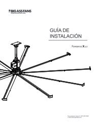
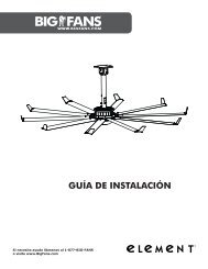
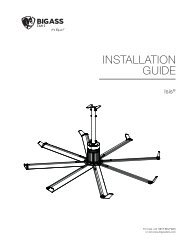
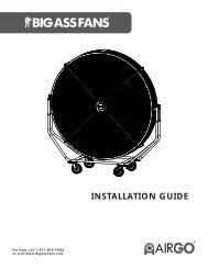
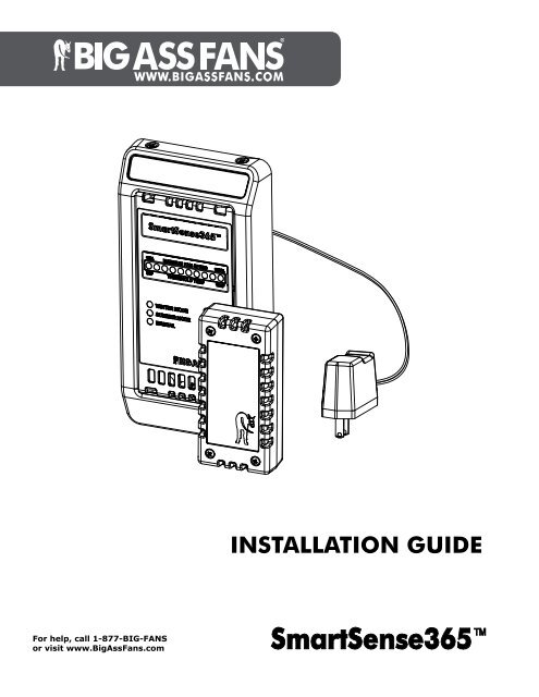
INSTALLATION GUIDE
SMARTSENSE365 <br />
Contents<br />
Introduction Thank You 1<br />
About <strong>Big</strong> <strong>Ass</strong> <strong>Fans</strong> 1<br />
About the SmartSense365 1<br />
Pre-Installation What’s in the Box 2<br />
Dimensions 3<br />
Mounting the SmartSense365 Overview 4<br />
SmartSense365 with Powerfoil ® X2.0 and Powerfoil ® X2.0Plus <strong>Fans</strong> 5<br />
SmartSense365 with Powerfoil ® 8 and Powerfoil ® 8Plus <strong>Fans</strong> 6<br />
Installing the Remote Temperature Sensor 7<br />
Installing the Wall Controller 8<br />
Electrical Installation Electrical Installation Safety 9<br />
Power Guidelines 9<br />
Single Fan Installation for PowerfoilX2.0 and PowerfoilX2.0Plus <strong>Fans</strong> 10<br />
Multi-Fan Installation (Daisy Chaining) for PowerfoilX2.0 and PowerfoilX2.0Plus<br />
<strong>Fans</strong> 11<br />
Single Fan Installation for Powerfoil8 and Powerfoil8Plus <strong>Fans</strong> 12<br />
Multi-Fan Installation (Daisy Chaining) for Powerfoil8 and Powerfoil8Plus <strong>Fans</strong> 13<br />
Alternative Wiring Methods 14<br />
Operating the SmartSense365 Starting and Stopping the Fan 15<br />
Modes of Operation 16<br />
Programming the<br />
SmartSense365<br />
Selecting a Mode 17<br />
Programming Winter Mode Maximum Fan Speed 17<br />
Programming Summer Mode Minimum and Maximum Temperatures 17<br />
Adjusting Manual Mode Fan Speed 17<br />
Troubleshooting Wall Controller 18<br />
Remote Temperature Sensor 18<br />
WWW.BIGASSFANS.COM ©2011 DELTA T CORP. DBA BIG ASS FANS ALL RIGHTS RESERVED
SMARTSENSE365 <br />
IMPORTANT SAFETY INSTRUCTIONS<br />
READ AND SAVE THESE INSTRUCTIONS<br />
WARNING: This guide is intended to provide a basic overview for integrating a SmartSense365 with a <strong>Big</strong> <strong>Ass</strong> Fan. Consult<br />
the Installation Guide included with the fan for additional installation and operation instructions.<br />
WARNING: Disconnect fan and controller from power supply before installing the SmartSense365.<br />
WARNING: To reduce the risk of electric shock, wiring should be performed by a qualified electrician! Incorrect assembly can<br />
cause electric shock or damage the motor and the controller! Hazard of electrical shock!<br />
WARNING: Installation must be in accordance with the National Electrical Code, ANSI/NFPA 70-1999, and all local codes.<br />
The procedures and techniques outlined in this manual are merely a guide for proper installation. Code compliance is your<br />
responsibility! Failure to comply with these codes could result in personal injury or property damage.<br />
WARNING: The fan controllers contain high voltage capacitors which take time to discharge after removal of mains supply.<br />
Before working on the fan controller, ensure isolation of mains supply from line inputs at the fan controller’s disconnect (L1,<br />
L2/N, 3). Wait three minutes for capacitors to discharge to safe voltage levels. Failure to do so may result in personal injury or<br />
death. Note: Darkened display LEDs are not an indication of safe voltage levels.<br />
WARNING: When service or replacement of a fan component requires the removal or disconnection of a safety device, the<br />
safety device is to be reinstalled or remounted as previously installed.<br />
CAUTION: The <strong>Big</strong> <strong>Ass</strong> <strong>Fans</strong> product warranty will not cover equipment damage or failure that is caused by improper<br />
installation.<br />
WWW.BIGASSFANS.COM ©2011 DELTA T CORP. DBA BIG ASS FANS ALL RIGHTS RESERVED
Thank you<br />
SMARTSENSE365 <br />
Introduction<br />
1<br />
Thank you and congratulations on your purchase of a <strong>Big</strong> <strong>Ass</strong> Fan, an efficient and cost-effective way to stay cool in the summer and<br />
warm in the winter. The revolutionary design of our fans combines the best of both form and function to bring power performance and a<br />
sleek look to any setting. More importantly, you have purchased a product that is backed by extensive research, thorough testing, and<br />
quality manufacturing. We’re ready to answer any questions or comments at 1-877-BIG-FANS or visit our Web site at<br />
www.bigassfans.com.<br />
Who we are and what we do<br />
<strong>Big</strong> <strong>Ass</strong> <strong>Fans</strong> has been the preeminent manufacturer of large-diameter, low-speed fans since 1999. With a worldwide presence and<br />
located in beautiful Lexington, KY, we research, design, and manufacture the most effective air movement solutions on the market.<br />
Our never-ending commitment to quality and innovation keeps us at the leading edge of a burgeoning industry. With an eye to helping<br />
customers satisfy their needs, and a strong sense of corporate responsibility to the community, <strong>Big</strong> <strong>Ass</strong> <strong>Fans</strong> has redefined the way<br />
business is done.<br />
About the SmartSense365 <br />
The SmartSense365 is engineered to maximize both energy savings and comfort through year-round control of your <strong>Big</strong> <strong>Ass</strong> Fan.<br />
Supply voltage<br />
Power consumption<br />
Output<br />
Wiring<br />
Operating temperature<br />
Humidity<br />
Storage temperature<br />
ESD withstand voltage<br />
Wall Controller<br />
+24VDC, 100mA<br />
≤1W<br />
4–20mA DC current loop<br />
18–22 AWG<br />
32°–100°F (0°–38°C)<br />
95% Relative humidity. Board is conformal coated.<br />
14°–122°F (-10°-50°C)<br />
+/- 4kV Air, +/- 4kV Contact<br />
Remote Temperature Sensor<br />
Supply voltage<br />
+10VDC to +24VDC<br />
Power consumption<br />
≤1W<br />
Output<br />
4–20mA DC current loop<br />
Accuracy/Non-linearity +/-1°@ 77°F/ =/-0.5°F<br />
Wiring<br />
18–22 AWG<br />
Operating temperature 32°–100°F (0°–38°C)<br />
Humidity<br />
95% Relative humidity. Board is conformal coated.<br />
Accuracy/Non-linearity 14°–122°F (-10°-50°C)<br />
ESD withstand voltage +/- 4kV Air, +/- 4kV Contact<br />
Wiring<br />
Max wiring distance (ft) ((V supply<br />
-10V)/0.02A) / (Wire Ohms per Foot x 2)<br />
Note: There is no concern regarding wiring distance regardless of wire gauge used. Using the formula above, the maximum wiring<br />
distance between devices would be 18,421 ft (3.5 mi) if 22 AWG stranded is used (0.019 ohms per ft).<br />
WWW.BIGASSFANS.COM ©2011 DELTA T CORP. DBA BIG ASS FAN CO. ALL RIGHTS RESERVED
2<br />
What’s in the box<br />
SMARTSENSE365 <br />
Pre-Installation<br />
CAUTION: The wall controller and remote temperature sensor contain sensitive electronic PCBs. Use extreme care when<br />
handling! ESD precautions recommended.<br />
The SmartSense365 is shipped in a single box and packaged in static shielding materials for ESD protection. Dashed lines indicate<br />
internal boxes. Review the information below to ensure you have received all necessary components for installation and operation.<br />
Note: Drawings are not to scale.<br />
Wall Controller &<br />
Mounting Hardware<br />
Power Cord<br />
Remote Temperature Sensor &<br />
Mounting Hardware<br />
WWW.BIGASSFANS.COM ©2011 DELTA T CORP. DBA BIG ASS FAN CO. ALL RIGHTS RESERVED
Dimensions<br />
SMARTSENSE365 <br />
Pre-Installation (cont.)<br />
3<br />
Remote Temperature Sensor<br />
1.9” (4.8 cm) 1”<br />
(2.5 cm)<br />
4” (10.2 cm)<br />
Mounting Plate<br />
Wall Controller<br />
3.86” (9.8 cm)<br />
2.8” (7 cm)<br />
5.1” (13 cm)<br />
7.25” (18.4 cm)<br />
Depth: 1” (2.5 cm)<br />
WWW.BIGASSFANS.COM ©2011 DELTA T CORP. DBA BIG ASS FAN CO. ALL RIGHTS RESERVED
4<br />
SMARTSENSE365 <br />
Mounting the SmartSense365 <br />
WARNING—TO REDUCE THE RISK OF FIRE, ELECTRIC SHOCK, OR INJURY TO PERSONS, OBSERVE THE FOLLOWING:<br />
a. Installation work and electrical wiring must be done by qualified person(s) in accordance with all applicable codes<br />
and standards.<br />
b. When cutting or drilling into a wall or ceiling, do not damage electrical wiring or other hidden utilities.<br />
Overview<br />
The SmartSense365 relies on air temperature readings obtained at the locations of the wall controller and remote temperature sensor.<br />
Proper mounting locations are essential to the successful adjustment of the room temperature. Refer to the diagram and guidelines<br />
below.<br />
ZONE 1<br />
ZONE 2<br />
ZONE 1. The remote temperature sensor must be mounted in the upper portion of the room (Zone 1) in order to obtain an accurate<br />
temperature reading at the ceiling level.<br />
ZONE 2. The wall controller must be mounted in the lower portion of the room (Zone 2) to obtain an accurate reading at the floor level.<br />
Do not mount the wall controller or remote sensor in the following locations:<br />
• Adjacent to or above radiant heaters<br />
• Near HVAC ventilation intakes or exhausts<br />
• On poorly insulated exterior walls<br />
• In roof decking<br />
• Near radiant heat sources<br />
WWW.BIGASSFANS.COM ©2011 DELTA T CORP. DBA BIG ASS FAN CO. ALL RIGHTS RESERVED
SMARTSENSE365 <br />
Mounting the SmartSense365 (cont.)<br />
SmartSense365 with Powerfoil ® X2.0 and Powerfoil ® X2.0Plus fans<br />
5<br />
Refer to the diagram below for the general installation of a SmartSense365 with Powerfoil ® X2.0 and Powerfoil ® X2.0Plus fans.<br />
Note: The PowerfoilX2.0/PowerfoilX2.0Plus fan wall controller and the SmartSense365 wall controller do not have to be mounted<br />
adjacent to one other; each device is wired independently. Wiring for both wall controllers can be routed in the same conduit.<br />
Ceiling-mounted Remote<br />
Temperature Sensor<br />
PowerfoilX2.0 or PowerfoilX2.0Plus<br />
Fan System with Integral Fan<br />
Controller<br />
F<br />
H<br />
U<br />
RUN STOP FWD REV REM LOC<br />
LOCAL<br />
MODE<br />
PU REM<br />
FWD<br />
PROG<br />
REV<br />
DATA<br />
10%<br />
FAN SPEED<br />
100%<br />
55°F THRESHOLD TEMPERATURE 100°F<br />
WINTER MODE<br />
SUMMER MODE<br />
MANUAL<br />
MODE<br />
Wall-mounted Controller<br />
with Lower Temperature Sensor<br />
(Mounting Plate not shown)<br />
RUN<br />
STOP<br />
RESET<br />
Class II AC Adapter<br />
24VDC, 0.25A<br />
WWW.BIGASSFANS.COM ©2011 DELTA T CORP. DBA BIG ASS FAN CO. ALL RIGHTS RESERVED
Wall mounted fan controller<br />
WARNING<br />
Safety Disconnect ONLY.<br />
DO NOT use this<br />
disconnect to normally<br />
operate the fan. Permanent<br />
damage may result!<br />
AUTO<br />
M<br />
R<br />
FWD<br />
REV<br />
F<br />
RUN<br />
STOP<br />
6<br />
SMARTSENSE365 <br />
Mounting the SmartSense365 (cont.)<br />
SmartSense365 with Powerfoil ® 8 and Powerfoil ® 8Plus fans<br />
Refer to the diagram below for the general installation of a SmartSense365 with Powerfoil ® 8 and Powerfoil ® 8Plus fans.<br />
Ceiling-mounted Remote<br />
Temperature Sensor<br />
Powerfoil8 or<br />
Powerfoil8Plus Fan<br />
2 conductor shielded<br />
cable 18-22AWG Stranded<br />
(provided by installer)<br />
Maximum distance > 1000 ft<br />
AUTOMATIC DESTRATIFICATION<br />
SYSTEM<br />
Wall-mounted Fan Controller<br />
10%<br />
FAN SPEED<br />
100%<br />
55°F THRESHOLD TEMPERATURE 100 °F<br />
WINTER MODE<br />
SUMMER MODE<br />
MANUAL<br />
Wall-mounted Controller with<br />
Lower Temperature Sensor<br />
(Mounting Plate not shown)<br />
MODE<br />
Cl II AC Adapter<br />
24VDC, 0.25A<br />
WWW.BIGASSFANS.COM ©2011 DELTA T CORP. DBA BIG ASS FAN CO. ALL RIGHTS RESERVED
SMARTSENSE365 <br />
Mounting the SmartSense365 (cont.)<br />
Installing the remote temperature sensor<br />
7<br />
CAUTION: The wall controller and remote temperature sensor contain sensitive electronic PCBs. Use extreme care when<br />
handling! ESD precautions recommended.<br />
Do not lose the rubber grommet during installation.<br />
The remote temperature sensor is designed to be surface mounted in a location near the ceiling. Note: Wiring for the remote sensor<br />
must be completed at the same time the sensor is mounted.<br />
To mount the remote temperature sensor, loosen the (4) screws and remove the cover from the remote sensor. Using the back of<br />
the sensor as a template, mark the (2) screw locations on the mounting surface. Loosely install the mounting screws on the mounting<br />
surface in the hole locations. Slide the remote over the screws, and then tighten the screws. Before reattaching the front cover,<br />
complete the wiring. See p. 9 for details and wiring diagrams. Note: The remote temperature sensor can be mounted in any orientation.<br />
Mounting<br />
Screws<br />
Front<br />
Cover<br />
Screws<br />
WWW.BIGASSFANS.COM ©2011 DELTA T CORP. DBA BIG ASS FAN CO. ALL RIGHTS RESERVED
8<br />
Installing the wall controller<br />
SMARTSENSE365 <br />
CAUTION: The wall controller and remote temperature sensor contain sensitive electronic PCBs. Use extreme care when<br />
handling! ESD precautions recommended.<br />
The SmartSense365 wall controller can be mounted to a standard 2” x 4” electrical switch box or surface-mounted on a wall or<br />
column. It does not have to be located adjacent to the fan controller; each controller is independently wired to the fan. Note: A junction<br />
box is not supplied with the wall controller.<br />
Mounting Hardware:<br />
a. (2) 6-32 x 7/8” Pan Head Screw<br />
b. (4) 6-32 Countersink Screw<br />
Mounting the SmartSense365 (cont.)<br />
Before mounting the SmartSense365 wall controller, route the wiring to the predetermined location.<br />
To install the wall controller:<br />
1. Attach the mounting plate to the junction box in the wall with the two (2) provided 6-32 x 7/8” pan head screws. Route the<br />
SmartSense365 wall controller power cord through the opening in the center of the mounting plate. Guide the power cord down the<br />
bottom of the mounting plate in the slot provided.<br />
2. Rest the wall controller in the wall controller cover, and then secure the controller cover to the mounting plate with the four (4)<br />
provided 6-32 countersink screws as shown below.<br />
b<br />
a<br />
Junction Box<br />
(in Wall)<br />
SmartSense365<br />
Wall Controller<br />
Mounting<br />
Plate<br />
(fits standard junction box)<br />
Controller<br />
Cover<br />
WWW.BIGASSFANS.COM ©2011 DELTA T CORP. DBA BIG ASS FAN CO. ALL RIGHTS RESERVED
SMARTSENSE365 <br />
Electrical Installation<br />
9<br />
WARNING: Disconnect fan and controller from power supply before installing the SmartSense365 .<br />
WARNING: To reduce the risk of electric shock, wiring should be performed by a qualified electrician! Incorrect assembly can<br />
cause electric shock or damage the motor and the controller! Hazard of electrical shock!<br />
WARNING: Installation must be in accordance with the National Electrical Code, ANSI/NFPA 70-1999, and all local codes.<br />
The procedures and techniques outlined in this manual are merely a guide for proper installation. Code compliance is your<br />
responsibility! Failure to comply with these codes could result in personal injury or property damage.<br />
WARNING: The fan controllers contain high voltage capacitors which take time to discharge after removal of mains supply.<br />
Before working on the fan controller, ensure isolation of mains supply from line inputs at the fan controller’s disconnect (L1,<br />
L2/N, L3). Wait three minutes for capacitors to discharge to safe voltage levels. Failure to do so may result in personal injury<br />
or death. Note: Darkened display LEDs are not an indication of safe voltage levels.<br />
Power guidelines<br />
Wall Controller<br />
Supply voltage<br />
+24VDC, 100mA<br />
Power consumption<br />
≤1W<br />
Output<br />
4–20mA DC current loop<br />
Wiring<br />
18–22 AWG<br />
ESD withstand voltage +/- 4kV Air, +/- 4kV Contact<br />
Remote Temperature Sensor<br />
Supply voltage<br />
+10VDC to +24VDC<br />
Output<br />
4–20mA DC current loop<br />
Accuracy/Non-linearity +/-1°@ 77°F/ =/-0.5°F<br />
Wiring<br />
18–22 AWG<br />
ESD withstand voltage +/- 4kV Air, +/- 4kV Contact<br />
WWW.BIGASSFANS.COM ©2011 DELTA T CORP. DBA BIG ASS FAN CO. ALL RIGHTS RESERVED
( pp )<br />
10<br />
SMARTSENSE365 <br />
Electrical Installation (cont.)<br />
Single fan installation for Powerfoil ® X2.0 and Powerfoil ® X2.0Plus fans<br />
Variable Frequency Drive at the Powerfoil ® X2.0 or<br />
Powerfoil ® X2.0Plus Fan Controller<br />
(cover removed)<br />
READY RUN FAULT<br />
ON<br />
1 2 3<br />
Change switches 1 & 2 to the<br />
DOWN position and switch 3<br />
to the UP position.<br />
SmartSense365 <br />
Remote Temperature<br />
Sensor<br />
ch in<br />
at left<br />
tion.<br />
Verify that<br />
AVI/ACI is set<br />
to the DOWN<br />
position for<br />
ACI mode.<br />
Verify that<br />
NPN/PNP is<br />
set to the UP<br />
position for<br />
NPN mode.<br />
AVI<br />
ACI<br />
NPN<br />
PNP<br />
RA RB RC<br />
+24VDC IN<br />
4-20mA OUT<br />
” (-)<br />
Analog Common “ACM” (-)<br />
Analog Current Input “ACI” (+)<br />
”(+)<br />
2 conductor shielded cable 18-22AWG Stranded<br />
(provided by installer) Maximum distance >1000 ft<br />
CAT5 Out to<br />
PFX wall pad<br />
Top of Wall Pad<br />
Reserved<br />
Reserved<br />
Reserved<br />
DC Common (shield)<br />
4-20mA Input from RTS<br />
+24VDC RTS Supply Out<br />
4-20mA Out to Fan Controller<br />
DC Common (shield)<br />
+24VDC Supply In<br />
DC Common (shield)<br />
SmartSense365<br />
Wall Controller<br />
WWW.BIGASSFANS.COM ©2011 DELTA T CORP. DBA BIG ASS FAN CO. ALL RIGHTS RESERVED
SMARTSENSE365 <br />
Electrical Installation (cont.)<br />
Multi-fan installation (daisy chaining) for Powerfoil ® X2.0 and Powerfoil ® X2.0Plus fans<br />
11<br />
Variable Frequency Drive at the Powerfoil ® X2.0<br />
or Powerfoil ® X2.0Plus Fan #1 Controller<br />
(cover removed)<br />
READY RUN FAULT<br />
ON<br />
1 2 3<br />
Change the<br />
switch in<br />
Position 3<br />
to the UP<br />
position.<br />
Change the<br />
switch in<br />
Position 3 to<br />
the DOWN<br />
position.<br />
Variable Frequency Drive at the<br />
PowerfoilX2.0 or PowerfoilX2.0Plus Fan #2<br />
Controller (cover removed)<br />
READY RUN FAULT<br />
ON<br />
1 2 3<br />
Verify that<br />
AVI/ACI is set<br />
to the DOWN<br />
position for<br />
ACI mode.<br />
Verify that<br />
NPN/PNP is<br />
set to the UP<br />
position for<br />
NPN mode.<br />
AVI<br />
ACI<br />
NPN<br />
PNP<br />
RA RB RC<br />
Analog Voltage Output “AFM” (+)<br />
Verify that<br />
AVI/ACI is<br />
set to the UP<br />
position for<br />
AVI mode.<br />
Analog Voltage Output “AFM” (+)<br />
Verify that<br />
NPN/PNP is<br />
set to the UP<br />
position for<br />
NPN mode.<br />
AVI<br />
ACI<br />
NPN<br />
PNP<br />
RA RB RC<br />
Analog Common “ACM” (-)<br />
Analog Common “ACM” (-)<br />
Analog Voltage Input “AVI” (+)<br />
Analog Current Input “ACI” (+)<br />
Input from<br />
SmartSense365 Output to up to two (2)<br />
F<br />
H<br />
U<br />
FWD REV REM LOC RUN STOP FWD REV REM LOC<br />
All fan wall controllers must be in “REM”<br />
mode for proper system operation.<br />
additional downstream<br />
fan controllers.<br />
Settings and wiring for<br />
remaining controllers<br />
shall be the same as<br />
those shown here for<br />
Fan #2.<br />
MODE<br />
LOCAL<br />
REM<br />
MODE<br />
LOCAL<br />
REM<br />
Green “RUN” button active<br />
Red “STOP/RESET” button active<br />
UP/DOWN button active<br />
Green “RUN” button disabled<br />
Red “STOP/RESET” button disabled<br />
UP/DOWN button disabled<br />
A maximum of four (4) fan controllers can be daisy chained.<br />
PROG<br />
FWD<br />
PROG<br />
WWW.BIGASSFANS.COM ©2011 DELTA T CORP. DBA BIG ASS FAN CO. ALL RIGHTS RESERVED
12<br />
SMARTSENSE365 <br />
Electrical Installation (cont.)<br />
Single fan installation for Powerfoil ® 8 and Powerfoil ® 8Plus fans<br />
Parameter Changes ARE required<br />
P101 ‘Standard Reference Source’ must be changed from “0” for keypad operation<br />
to “2” for 4-20mA analog input operation<br />
Variable Frequency Drive at the Powerfoil ® 8 or<br />
Powerfoil ® 8Plus Fan Controller<br />
(cover removed)<br />
SmartSense365 <br />
Remote Temperature<br />
Sensor<br />
1 2 5 6 25 4 11<br />
13A 13B 13C 14 30 16 17<br />
U/T1 V/T2 W/T3<br />
PE<br />
L1 L2 L3<br />
+24VDC IN<br />
4-20mA OUT<br />
2 conductor shielded cable 18-22AWG Stranded<br />
(provided by installer) Maximum distance >1000ft<br />
Top of Wall Pad<br />
Reserved<br />
Reserved<br />
Reserved<br />
DC Common (shield)<br />
4-20mA Input from RTS<br />
+24VDC RTS Supply Out<br />
4-20mA Out to Fan Controller<br />
DC Common (shield)<br />
+24VDC Supply In<br />
DC Common (shield)<br />
SmartSense365<br />
Wall Controller<br />
WWW.BIGASSFANS.COM ©2011 DELTA T CORP. DBA BIG ASS FAN CO. ALL RIGHTS RESERVED
SMARTSENSE365 <br />
Electrical Installation (cont.)<br />
Multi-fan installation (daisy chaining) for Powerfoil ® 8 and Powerfoil ® 8Plus fans<br />
13<br />
The following parameter changes are required on the first fan controller<br />
The following parameter changes are required on all downstream fan controllers<br />
P101 ‘Standard Reference Source’ must be changed from “0” for keypad<br />
operation to “2” for 4-20mA analog input operation<br />
P101 ‘Standard Reference Source’ must be changed from “0” for keypad<br />
operation to “1” for 0-10VDC analog input operation<br />
P150 ‘TB-30 Output’ must be changed from “0” for None to “1” for 0-10VDC<br />
output (scaled to drive output frequency)<br />
P102 ‘Minimum Frequency’ must be changed from “10.0” to “0.0” for proper<br />
minimum speed reference scaling from preceding fan controller<br />
P152 ‘TB-30 Scaling Frequency’ must be changed to equal the frequency<br />
setting of P103 ‘Maximum Frequency’<br />
P150 ‘TB-30 Output’ must be changed from “0” for None to “1” for 0-10VDC<br />
output (scaled to drive output frequency)<br />
P152 ‘TB-30 Scaling Frequency’ must be changed to equal the frequency<br />
setting of P103 ‘Maximum Frequency’<br />
Variable Frequency Drive at the Powerfoil ® 8 or<br />
Powerfoil ® 8Plus Fan #1 Controller<br />
(cover removed)<br />
Variable Frequency Drive at the Powerfoil8<br />
or Powerfoil8Plus Fan #2 Controller (cover<br />
removed)<br />
#30 = 0-10VDC Output<br />
#30 = 0-10VDC Output<br />
#25 = 4-20mA Input<br />
#5 = 0-10VDC Input<br />
#2 = Analog Common<br />
#2 = Analog Common<br />
1 2 5 6 25 4 11<br />
13A 13B 13C 14 30 16 17<br />
1 2 5 6 25 4 11<br />
13A 13B 13C 14 30 16 17<br />
PE<br />
PE<br />
U/T1 V/T2 W/T3 L1 L2 L3<br />
U/T1 V/T2 W/T3 L1 L2 L3<br />
2 conductor shielded cable 18-22AWG Stranded<br />
(provided by installer) Maximum distance
14<br />
Alternative wiring methods<br />
SMARTSENSE365 <br />
Electrical Installation (cont.)<br />
If there is not a 120VAC receptacle within six (6) feet of the desired SmartSense365 wall controller location, the installer can extend<br />
the cord of the provided power supply as needed or use one of the alternate wiring methods shown below utilizing a 3-conductor<br />
shielded cable.<br />
Collocate a +24VDC Supply with Controller<br />
Remote Temperature<br />
Sensor<br />
+24VIN<br />
4-20mA Out<br />
Fan Controller<br />
Analog Input<br />
4-20mA Input<br />
Analog Common<br />
+24VDC Supply<br />
Cable Shield<br />
Drain Leads<br />
(if present)<br />
DC Common<br />
+24VDC<br />
reserved<br />
reserved<br />
reserved<br />
DC Common (shield)<br />
RTS Input<br />
+24VDC RTS Supply<br />
4-20mA Output to Fan<br />
DC Common (shield)<br />
+24VDC<br />
DC Common (shield)<br />
SmartSense365<br />
Controller<br />
Collocate a +24VDC Supply with Remote<br />
Temperature Sensor<br />
Remote Temperature<br />
Sensor<br />
4-20mA Out<br />
+24VIN<br />
Fan Controller<br />
Analog Input<br />
4-20mA Input<br />
Analog Common<br />
+24VDC Supply<br />
+24VDC<br />
DC Common<br />
Cable Shield<br />
Drain Leads<br />
(if present)<br />
reserved<br />
reserved<br />
reserved<br />
DC Common (shield)<br />
RTS Input<br />
+24VDC RTS Supply<br />
4-20mA Output to Fan<br />
DC Common (shield)<br />
+24VDC<br />
DC Common (shield)<br />
SmartSense365<br />
Controller<br />
WWW.BIGASSFANS.COM ©2011 DELTA T CORP. DBA BIG ASS FAN CO. ALL RIGHTS RESERVED
SMARTSENSE365 <br />
Operating the SmartSense365 <br />
15<br />
Destratification is the process by which air is circulated within a space to prevent<br />
temperature gradients (stratification) from forming. Depending on the volume of the space<br />
and the size of fan used, the minimum fan speed required to destratify can vary greatly<br />
throughout the day due to a variety of factors. In Winter Mode, the SmartSense365 is<br />
designed to automatically adjust the fan to the optimal low speed by sampling temperature<br />
readings at both the ceiling and floor levels. In Summer Mode, the SmartSense365 adjusts<br />
fan speed to maintain a user-specified temperature by sampling temperature readings at the<br />
floor level only. See the following pages for more information on the modes of operation and<br />
to learn how to program your SmartSense365.<br />
Reserved<br />
Reserved<br />
Reserved<br />
DC Common<br />
4-20mA Input from RTS<br />
+24VDC RTS Supply Out<br />
4-20mA Out to Fan Controller<br />
DC Common<br />
+24VDC Supply In<br />
DC Common<br />
Starting and stopping the fan is controlled by the fan wall controller. The<br />
SmartSense365 wall controller only provides a speed reference for the fan.<br />
10%<br />
55°F<br />
MAXIMUM FAN SPEED<br />
THRESHOLD TEMPERATURE<br />
100%<br />
100°F<br />
Starting and stopping the fan<br />
Powerfoil ® X2.0 and Powerfoil ® X2.0Plus fans<br />
The Powerfoil ® X2.0 and Powerfoil ® X2.0Plus fans are pre-configured at the factory to<br />
accept dual control sources. The wall controller keypad allows you to toggle these sources<br />
easily using the “LOCAL/REM” button. When the LOC indicator is illuminated on the fan’s<br />
wall controller, the Start, Stop, and Speed functions are controlled solely by the fan’s<br />
wall controller. When the REM indicator is illuminated, the fan speed is controlled by the<br />
SmartSense365 wall controller.<br />
To start the fan, press the “RUN” button on the fan wall controller. After starting the fan,<br />
switch to REM mode to utilize the SmartSense365 wall controller. To stop the fan, the<br />
“LOCAL/REM” button must be pressed again for LOC mode to reactivate the “STOP/RESET”<br />
Back<br />
button.<br />
WINTER MODE<br />
SUMMER MODE<br />
MANUAL<br />
Front<br />
MODE<br />
LOC Illuminated<br />
REM Illuminated<br />
WD REV<br />
REM LOC<br />
WD REV<br />
REM LOC<br />
DE<br />
LOCAL<br />
REM<br />
DE<br />
LOCAL<br />
REM<br />
Green “RUN” button active<br />
Red “STOP/RESET” button active<br />
UP/DOWN button active<br />
Green “RUN” button disabled<br />
Red “STOP/RESET” button disabled<br />
UP/DOWN button disabled<br />
Powerfoil ® 8 and Powerfoil ® 8Plus fans<br />
The fan controller will operate in the same manner as it did prior to installing the<br />
SmartSense365.<br />
AUTO<br />
FWD<br />
RUN<br />
STOP<br />
The RUN and STOP buttons are still enabled for fan<br />
operation.<br />
These buttons are now disabled for speed selection.<br />
M<br />
R<br />
REV<br />
F<br />
RUN<br />
STOP<br />
WWW.BIGASSFANS.COM ©2011 DELTA T CORP. DBA BIG ASS FAN CO. ALL RIGHTS RESERVED
16<br />
Modes of operation<br />
Reserv<br />
Reserv<br />
Reserv<br />
DC Comm<br />
4-20mA Input from R<br />
+24VDC RTS Supply O<br />
4-20mA Out to Fan Control<br />
DC Comm<br />
+24VDC Supply<br />
DC Comm<br />
SMARTSENSE365 <br />
Operating the SmartSense365 (cont.)<br />
The Mode button on the SmartSense365 controller is responsible for selecting one of<br />
the three modes of operation: Winter, Summer, and Manual. When a mode is selected,<br />
the corresponding LED illuminates to show it is active.<br />
10%<br />
DESTRATIFICATION SYSTEM<br />
55°F<br />
MAXIMUM FAN SPEED<br />
THRESHOLD TEMPERATURE<br />
100%<br />
100°F<br />
Note: The maximum speed in Winter Mode is the speed at which the fan is running as<br />
fast as possible without creating a draft. In Summer Mode, the maximum winter speed is<br />
the minimum summer speed. Any increase in speed beyond that point provides a cooling<br />
effect.<br />
WINTER MODE<br />
SUMMER MODE<br />
MANUAL<br />
Winter Mode<br />
In Winter Mode, the SmartSense365 monitors the difference in temperatures at the<br />
floor and ceiling levels, i.e., the Delta T. Based on the Delta T of the space, fan speed automatically adjusts to maintain a uniform<br />
temperature between the floor and ceiling (full destratification) while using the lowest fan speed possible to further reduce energy<br />
consumption and increase HVAC equipment efficiency (if present).<br />
Summer Mode<br />
In Summer Mode, the SmartSense365 monitors only the temperature at the floor level. Based on this reading, fan speed adjusts<br />
according to the user-defined temperature and speed setting. See the following page for programming instructions.<br />
Below are two examples of how the SmartSense365 can Back be programmed. In Example 1, the maximum winter fan speed is limited to<br />
Front<br />
30%. The summer minimum speed temperature is set to 65°F. When the floor temperature exceeds 65°F, the fan speed will increase<br />
(starting at winter maximum) proportionally with the temperature. The summer maximum speed temperature is set to 85°F, which is the<br />
temperature at which the fan will reach full speed.<br />
MODE<br />
Fan Speed 100%<br />
Example 1 Example 2<br />
Fan Speed 100%<br />
Winter<br />
Maximum<br />
Speed (30%)<br />
10%<br />
Winter<br />
Maximum<br />
Speed (25%)<br />
10%<br />
50°F<br />
Temperature 100°F<br />
50°F<br />
Temperature 100°F<br />
Summer<br />
Minimum Speed<br />
Temp (65°F)<br />
Summer<br />
Maximum Speed<br />
Temp (85°F)<br />
Summer<br />
Minimum Speed<br />
Temp (67.5°F)<br />
Summer<br />
Maximum Speed<br />
Temp (95°F)<br />
Manual Mode<br />
In Manual mode, you can manually change the speed of the fan to suit your needs by pressing the Up or Down arrow buttons.<br />
WWW.BIGASSFANS.COM ©2011 DELTA T CORP. DBA BIG ASS FAN CO. ALL RIGHTS RESERVED
SMARTSENSE365 <br />
Programming the SmartSense365 <br />
17<br />
Selecting a mode<br />
To select a mode, repeatedly press the Mode button until the green Winter Mode LED, red Summer Mode LED, or yellow Manual<br />
Mode LED is illuminated.<br />
AUTOMATIC<br />
Reserved<br />
Reserved<br />
Reserved<br />
DC Common<br />
4-20mA Input from RTS<br />
+24VDC RTS Supply Out<br />
4-20mA Out to Fan Controller<br />
DC Common<br />
+24VDC Supply In<br />
DC Common<br />
Programming Winter Mode maximum fan speed<br />
To program the maximum fan speed for Winter Mode:<br />
1. After selecting Winter Mode, press and hold the Mode<br />
button for three (3) seconds. The Winter Mode LED will<br />
flash.<br />
2. Press the Up and Down Arrow buttons to adjust<br />
the fan speed until a breeze can barely be felt. It is<br />
recommended that the speed be reduced from this<br />
point by 5%. The goal is to find the maximum allowable<br />
speed of the fan that does not produce a wind chill<br />
effect or any discomfort.<br />
Note: Each LED on the Maximum Fan Speed Bar<br />
represents a 10% increase or decrease in speed<br />
adjustment. When two LEDs are simultaneously<br />
illuminated, the second LED indicates a 5% increase<br />
(e.g., 15%, 25%, 35%, etc.).<br />
Flashing<br />
when in<br />
programming<br />
mode<br />
10%<br />
DESTRATIFICATION SYSTEM<br />
55°F<br />
MAXIMUM FAN SPEED<br />
THRESHOLD TEMPERATURE<br />
WINTER MODE<br />
SUMMER MODE<br />
MANUAL<br />
MODE<br />
85% Speed Displayed<br />
3. Press the Mode button once to save the Winter Max Speed setting and to exit programming mode. The Winter Mode LED will stop<br />
flashing and the Maximum Fan Speed Bar LEDs will show the fan’s current speed.<br />
100%<br />
100°F<br />
5% Speed<br />
Increase<br />
5% Speed<br />
Decrease<br />
Programming Summer Mode minimum and maximum temperatures<br />
To program the minimum and maximum speed<br />
temperatures for Summer Mode:<br />
1. After selecting Summer Mode, press Backand hold the<br />
Mode button for three (3) seconds. The Summer<br />
Mode LED will flash.<br />
2. To set the Minimum Speed Temperature, press the<br />
Up and Down Arrow buttons to adjust the minimum<br />
speed temperature. Each press of an Arrow button<br />
changes the setting in 2.5°F increments.<br />
Note: Each LED on the Threshold Temperature Bar<br />
indicates a 5°F increase or decrease in temperature<br />
adjustment. When two LEDs are simultaneously<br />
illuminated, the second LED indicates 5° (e.g., 62.5°,<br />
67.5°, 72.5°, etc.).<br />
3. Press the Mode button once to save the Summer<br />
Minimum Speed Temperature. The Summer Mode LED will flash, indicating that the SmartSense365 is ready to accept a<br />
Maximum Speed Temperature.<br />
4. To set the Maximum Speed Temperature, press the Up and Down Arrow buttons to adjust the maximum speed temperature. Each<br />
press of an Arrow button changes the setting in 2.5°F increments.<br />
5. Press the Mode button once to save the Summer Maximum Speed Temperature. The Summer Mode LED will stop flashing and the<br />
Threshold Temperature LEDs will show the fan’s current speed.<br />
Adjusting Manual Mode fan speed<br />
Flashing<br />
when in<br />
programming<br />
mode<br />
To manually adjust the fan speed, select Manual Mode, and then press the Up and Down buttons to adjust the fan speed between<br />
10% and 100% as desired.<br />
Front<br />
50°F THRESHOLD TEMPERATURE 100°F<br />
WINTER MODE<br />
SUMMER MODE<br />
MANUAL<br />
MODE<br />
87.5° Speed Temp<br />
Displayed<br />
5% Speed<br />
Increase<br />
5% Speed<br />
Decrease<br />
WWW.BIGASSFANS.COM ©2011 DELTA T CORP. DBA BIG ASS FAN CO. ALL RIGHTS RESERVED
18<br />
SMARTSENSE365 <br />
Troubleshooting<br />
CAUTION: Remove power from the SmartSense365 prior to disconnecting or connecting any portion of the associated<br />
wiring when performing any of the procedures below.<br />
During operation, the fan controller keypad display will typically show the command frequency from the SmartSense365 wall controller.<br />
If the display reports the error code shown below accompanied by fan shutdown or slowdown, one of the following conditions has<br />
occurred:<br />
• The 4–20mA loop circuit between the fan controller and the SmartSense365 wall controller has failed. Remove system power and<br />
check for short circuits and/or open circuit conditions. See below for more information.<br />
• The SmartSense365 wall controller power has been removed during normal operation. Check +24VDC power supply and associated<br />
connections.<br />
• Component failure at the SmartSense365 or at the fan controller. See below for more information.<br />
Powerfoil ® X2.0 or Powerfoil ® X2.0Plus<br />
Fan Keypad “Analog Error”<br />
Powerfoil ® 8 or Powerfoil ® 8Plus<br />
Fan Keypad “4–20 mA Signal Loss” Error<br />
AUTO<br />
FWD<br />
F<br />
H<br />
U<br />
RUN STOP FWD REV REM LOC<br />
M<br />
R<br />
REV<br />
F<br />
RUN<br />
STOP<br />
Wall controller<br />
Checking output circuit continuity<br />
The analog current input on the fan controller has an input impedance of 250 ohms. Measure this value at the analog input terminals of<br />
the fan controller (terminals ACM-ACI).<br />
Remove the “4–20mA output” wires at the SmartSense365 wall controller, and then measure the same 250-ohm input impedance plus<br />
the resistance of the cable used for installation on the output circuit wiring.<br />
Checking output circuit current<br />
The SmartSense365 wall controller provides a 4–20mA current to the fan controller for speed reference.<br />
To check the output circuit current, remove power from the SmartSense365 wall controller. Place a multi-meter (set to mA DC) in line<br />
with one of the mA output conductors. Reapply power. Set the SmartSense365 to Manual Mode. The loop current should be between<br />
4mA–20mA in accordance with the speed adjustment buttons on the SmartSense365 keypad.<br />
Remote temperature sensor<br />
Checking output circuit current<br />
Because the load impedance of the remote temperature sensor is in excess of 1 Mohm, the best way to test the remote temperature<br />
sensor is to measure the mA signal from the sensor while the system is in operation.<br />
Remove power. Place a multi-meter (set to mA DC) in line with one of the remote’s conductors. Reapply power. The remote temperature<br />
sensor signal should read between 4–20mADC. This reading can be converted to degrees Fahrenheit using the following formula:<br />
Degrees F = 18.7 x mA - 74 Example: 86°F = 18.7 x 8.55mA - 74<br />
WWW.BIGASSFANS.COM ©2011 DELTA T CORP. DBA BIG ASS FAN CO. ALL RIGHTS RESERVED
230412<br />
REV B<br />
2425 Merchant Street Lexington, KY 40511 1-877-BIG-FANS