2 - Big Ass Fans
2 - Big Ass Fans
2 - Big Ass Fans

You also want an ePaper? Increase the reach of your titles
YUMPU automatically turns print PDFs into web optimized ePapers that Google loves.
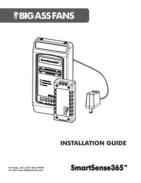
For help, call 1-877-BIG-FANSor visit www.<strong>Big</strong><strong>Ass</strong><strong>Fans</strong>.comINSTALLATION GUIDE
Installation Guide:Oct. 2013Rev. E<strong>Big</strong> <strong>Ass</strong> Fan Company2348 Innovation DriveLexington, KY 405111-877-BIG-FANSwww.bigassfans.comMay be covered by one or more of the following United States patents:6,244,821; 6,589,016; 6,817,835; 6,939,108; 7,252,478; 7,284,960; D587,799; D607,988; 7,654,798; D635,237; 7,934,907; D641,075;D642,674; 8,075,273; D650,893; 8,079,823; 8,147,182; 8,147,204; 8,152,453; 8,162,613; and other patents pending.SmartSense365 is a trademark of Delta T Corporation. All other trademarks used herein are the properties of their respective owners.
SMARTSENSE365 ContentsIntroduction Thank You 1About <strong>Big</strong> <strong>Ass</strong> <strong>Fans</strong> 1About the SmartSense365 1Pre-Installation What’s in the Box 2Dimensions 3Mounting the SmartSense365 Overview 4SmartSense365 with Powerfoil ® X2.0 and Powerfoil ® X2.0Plus <strong>Fans</strong> 5SmartSense365 with Powerfoil ® 8 and Powerfoil ® 8Plus <strong>Fans</strong> 6Mounting the Remote Temperature Sensor 7Mounting the Wall Controller 8Electrical Installation Electrical Installation Safety 9Power Guidelines 9Single Fan Installation for PowerfoilX2.0 and PowerfoilX2.0Plus <strong>Fans</strong> 10Multi-Fan Installation (Daisy Chaining) for PowerfoilX2.0 and PowerfoilX2.0Plus<strong>Fans</strong> 11Single Fan Installation for Powerfoil8 and Powerfoil8Plus <strong>Fans</strong> 12Multi-Fan Installation (Daisy Chaining) for Powerfoil8 and Powerfoil8Plus <strong>Fans</strong> 13Alternative Wiring Methods 14Operating the SmartSense365 Starting and Stopping the Fan 15Modes of Operation 16Programming theSmartSense365Selecting a Mode 17Programming Winter Mode Maximum Fan Speed 17Programming Summer Mode Minimum and Maximum Temperatures 17Adjusting Manual Mode Fan Speed 17Troubleshooting Wall Controller 18Remote Temperature Sensor 18WWW.BIGASSFANS.COM ©2011 DELTA T CORP. DBA BIG ASS FANS ALL RIGHTS RESERVED
SMARTSENSE365 IMPORTANT SAFETY INSTRUCTIONSREAD AND SAVE THESE INSTRUCTIONSWARNING: This guide is intended to provide a basic overview for integrating a SmartSense365 with a <strong>Big</strong> <strong>Ass</strong> Fan. Consultthe Installation Guide included with the fan for additional installation and operation instructions.WARNING: Disconnect fan and controller from power supply before installing the SmartSense365.WARNING: Installation must be in accordance with the National Electrical Code, ANSI/NFPA 70-2011, and all local codes.The procedures and techniques outlined in this manual are merely a guide for proper installation. Code compliance is yourWARNING: The fan controllers contain high voltage capacitors which take time to discharge after removal of mains supply.Before working on the fan controller, ensure isolation of mains supply from line inputs at the fan controller’s disconnect (L1,death. Note: Darkened display LEDs are not an indication of safe voltage levels.WARNING: When service or replacement of a fan component requires the removal or disconnection of a safety device, thesafety device is to be reinstalled or remounted as previously installed.CAUTION: The <strong>Big</strong> <strong>Ass</strong> <strong>Fans</strong> product warranty will not cover equipment damage or failure that is caused by improperinstallation.ATTENTION: If installing the fan in the United States, the fan must be installed per the following National Fire Protection<strong>Ass</strong>ociation (NFPA) guidelines: WWW.BIGASSFANS.COM ©2011 DELTA T CORP. DBA BIG ASS FANS ALL RIGHTS RESERVED
About the SmartSense365 SMARTSENSE365 IntroductionThank you and congratulations on your purchase of a <strong>Big</strong> <strong>Ass</strong> warm in the winter. The revolutionary design of our fans combines the best of both form and function to bring power performance and asleek look to any setting. More importantly, you have purchased a product that is backed by extensive research, thorough testing, andquality manufacturing. We’re ready to answer any questions or comments at 1-877-BIG-FANS or visit our Web site atwww.bigassfans.com.Who we are and what we do<strong>Big</strong> <strong>Ass</strong> <strong>Fans</strong> has been the preeminent manufacturer of large-diameter, low-speed fans since 1999. With a worldwide presence andlocated in beautiful Lexington, KY, we research, design, and manufacture the most effective air movement solutions on the market.Our never-ending commitment to quality and innovation keeps us at the leading edge of a burgeoning industry. With an eye to helpingcustomers satisfy their needs, and a strong sense of corporate responsibility to the community, <strong>Big</strong> <strong>Ass</strong> business is done.The SmartSense365 is engineered to maximize both energy savings and comfort through year-round control of your <strong>Big</strong> <strong>Ass</strong> Fan.1Supply voltagePower consumptionOutputWiringOperating temperatureHumidityStorage temperatureESD withstand voltageWall Controller+24VDC, 100mA4–20mA DC current loop18–22 AWG32°–100°F (0°–38°C)95% Relative humidity. Board is conformal coated.14°–122°F (-10°–50°C)+/- 4kV Air, +/- 4kV ContactRemote Temperature SensorSupply voltage+10VDC to +24VDCPower consumptionOutput4–20mA DC current loopAccuracy/Non-linearity +/-1°@ 77°F/ =/-0.5°FWiring18–22 AWGOperating temperature 32°–100°F (0°–38°C)Humidity95% Relative humidity. Board is conformal coated.Storage temperature14°–122°F (-10°–50°C)ESD withstand voltage +/- 4kV Air, +/- 4kV ContactWiringMax wiring distance (ft) ((V supply-10V)/0.02A) / (Wire Ohms per Foot x 2)Note: There is no concern regarding wiring distance regardless of wire gauge used. Using the formula above, the maximum wiringdistance between devices would be 18,421 ft (3.5 mi) if 22 AWG stranded is used (0.019 ohms per ft).WWW.BIGASSFANS.COM ©2011 DELTA T CORP. DBA BIG ASS FAN CO. ALL RIGHTS RESERVED
2What’s in the boxSMARTSENSE365 Pre-InstallationCAUTION: The wall controller and remote temperature sensor contain sensitive electronic PCBs. Use extreme care whenThe SmartSense365 is shipped in a single box and packaged in static shielding materials for ESD protection. Dashed lines indicateinternal boxes. Review the information below to ensure you have received all necessary components for installation and operation.Note: Drawings are not to scale.Wall Controller &Mounting HardwarePower CordRemote Temperature Sensor &Mounting HardwareWWW.BIGASSFANS.COM ©2011 DELTA T CORP. DBA BIG ASS FAN CO. ALL RIGHTS RESERVED
DimensionsSMARTSENSE365 Pre-Installation (cont.)Remote Temperature Sensor31.9” (4.8 cm) 1”(2.5 cm)4” (10.2 cm)Mounting PlateWall Controller3.86” (9.8 cm)2.8” (7 cm)5.1” (13 cm)7.25” (18.4 cm)Depth: 1” (2.5 cm)WWW.BIGASSFANS.COM ©2011 DELTA T CORP. DBA BIG ASS FAN CO. ALL RIGHTS RESERVED
SMARTSENSE365 Mounting the SmartSense365 WARNING—TO REDUCE THE RISK OF FIRE, ELECTRIC SHOCK, OR INJURY TO PERSONS, OBSERVE THE FOLLOWING:a. standards.b. When cutting or drilling into a wall or ceiling, do not damage electrical wiring or other hidden utilities.OverviewThe SmartSense365 relies on air temperature readings obtained at the locations of the wall controller and remote temperature sensor.Proper mounting locations are essential to the successful adjustment of the room temperature. Refer to the diagram and guidelinesbelow.ZONE 1ZONE 2ZONE 1. The remote temperature sensor must be mounted in the upper portion of the room (Zone 1) in order to obtain an accuratetemperature reading at the ceiling level.ZONE 2.foreign objects or moving equipment. The wall controller should be readily accessible.Do not mount the wall controller or remote sensor in the following locations: Adjacent to or above radiant heaters Near HVAC ventilation intakes or exhausts On poorly insulated exterior walls In roof decking Near radiant heat sourcesWWW.BIGASSFANS.COM ©2011 DELTA T CORP. DBA BIG ASS FAN CO. ALL RIGHTS RESERVED
Wall mounted fan controllerWARNINGSafety Disconnect ONLY.DO NOT use thisdisconnect to normallyoperate the fan. Permanentdamage may result!AUTOMRFWDREVFRUNSTOP6SMARTSENSE365 Mounting the SmartSense365 (cont.)SmartSense365 with Powerfoil ® 8 and Powerfoil ® 8Plus fansRefer to the diagram below for the general installation of a SmartSense365 with Powerfoil ® 8 and Powerfoil ® 8Plus fans.Ceiling-mounted RemoteTemperature SensorPowerfoil8 orPowerfoil8Plus Fan2 conductor shieldedcable 18-22AWG Stranded(provided by installer)Maximum distance > 1000 ftAUTOMATIC DESTRATIFICATIONSYSTEMWall-mounted Fan Controller10 %FAN SPEED100 %55 °F THRESHOLD TEMPERATURE 100 °FWINTER MODESUMMER MODEMANUALWall-mounted Controller withLower Temperature Sensor(Mounting Plate not shown)MODECl II AC AdapterWWW.BIGASSFANS.COM ©2011 DELTA T CORP. DBA BIG ASS FAN CO. ALL RIGHTS RESERVED
SMARTSENSE365 Mounting the SmartSense365 (cont.)Mounting the remote temperature sensor7CAUTION: The wall controller and remote temperature sensor contain sensitive electronic PCBs. Use extreme care whenDo not lose the rubber grommet during installation.The remote temperature sensor is designed to be surface mounted in a location near the ceiling. Note: Wiring for the remote sensormust be completed at the same time the sensor is mounted.To mount the remote temperature sensor, loosen the (4) screws and remove the cover from the remote sensor. Using the back ofthe sensor as a template, mark the (2) screw locations on the mounting surface. Loosely install the mounting screws on the mountingsurface in the hole locations. Slide the remote over the screws, and then tighten the screws. Before reattaching the front cover,complete the wiring. See p. 9 for details and wiring diagrams. Note: The remote temperature sensor can be mounted in any orientation.MountingScrewsFrontCoverScrewsWWW.BIGASSFANS.COM ©2011 DELTA T CORP. DBA BIG ASS FAN CO. ALL RIGHTS RESERVED
8Mounting the wall controllerSMARTSENSE365 CAUTION: The wall controller and remote temperature sensor contain sensitive electronic PCBs. Use extreme care whenThe SmartSense365 wall controller can be mounted to a standard 2” x 4” electrical switch box or surface-mounted on a wall orcolumn. It does not have to be located adjacent to the fan controller; each controller is independently wired to the fan. Note: A junctionbox is not supplied with the wall controller.To install the wall controller:1. Attach the mounting plate to the junction box in the wall with the two (2) provided 6-32 x 7/8” pan head screws. Route theSmartSense365 wall controller power cord through the opening in the center of the mounting plate. Guide the power cord down thebottom of the mounting plate in the slot provided.2. Rest the wall controller in the wall controller cover, and then secure the controller cover to the mounting plate with the four (4)provided 6-32 countersink screws as shown below.Mounting Hardware:a. (2) 6-32 x 7/8” Pan Head Screwb. (4) 6-32 Countersink ScrewMounting the SmartSense365 (cont.)Before mounting the SmartSense365 wall controller, route the wiring to the predetermined location.baJunction Box(in Wall)SmartSense365Wall ControllerMountingPlateControllerCoverWWW.BIGASSFANS.COM ©2011 DELTA T CORP. DBA BIG ASS FAN CO. ALL RIGHTS RESERVED
SMARTSENSE365 Electrical InstallationWARNING: Disconnect fan and controller from power supply before installing the SmartSense365 .WARNING: Installation must be in accordance with the National Electrical Code, ANSI/NFPA 70-2011, and all local codes.The procedures and techniques outlined in this manual are merely a guide for proper installation. Code compliance is yourWARNING: The fan controllers contain high voltage capacitors which take time to discharge after removal of mains supply.Before working on the fan controller, ensure isolation of mains supply from line inputs at the fan controller’s disconnect (L1,or death. Note: Darkened display LEDs are not an indication of safe voltage levels.Power guidelinesWall ControllerSupply voltage+24VDC, 100mAPower consumptionOutput4–20mA DC current loopWiring18–22 AWGESD withstand voltage +/- 4kV Air, +/- 4kV ContactRemote Temperature SensorSupply voltage+10VDC to +24VDCOutput4–20mA DC current loopAccuracy/Non-linearity +/-1°@ 77°F/ =/-0.5°FWiring18–22 AWGESD withstand voltage +/- 4kV Air, +/- 4kV ContactWWW.BIGASSFANS.COM ©2011 DELTA T CORP. DBA BIG ASS FAN CO. ALL RIGHTS RESERVED
10SMARTSENSE365 Electrical Installation (cont.)Single fan installation for Powerfoil ® X2.0 and Powerfoil ® X2.0Plus fansVariable Frequency Drive at the Powerfoil ® X2.0 orPowerfoil ® X2.0Plus Fan Controller(cover removed)READY RUN FAULTON1 2 3Change switches 1 & 2 to theDOWN position and switch 3to the UP position.SmartSense365 Remote TemperatureSensorVerify thatAVI/ACI is setto the DOWNposition forACI mode.Verify thatNPN/PNP isset to the UPposition forNPN mode.AVIACINPNPNPRA RB RCAnalog Common “ACM” (-)Analog Current Input “ACI” (+)2 conductor shielded cable 18-22AWG Stranded(provided by installer) Maximum distance >1000 ftCAT5 Out toPFX wall padTop of Wall PadReservedReservedReservedDC Common (shield)4-20mA Input from RTS+24VDC RTS Supply Out4-20mA Out to Fan ControllerDC Common (shield)+24VDC Supply InDC Common (shield)SmartSense365Wall ControllerWWW.BIGASSFANS.COM ©2011 DELTA T CORP. DBA BIG ASS FAN CO. ALL RIGHTS RESERVED
SMARTSENSE365 Electrical Installation (cont.)Multi-fan installation (daisy chaining) for Powerfoil ® X2.0 and Powerfoil ® X2.0Plus fans11Variable Frequency Drive at the Powerfoil ® X2.0or Powerfoil ® X2.0Plus Fan #1 Controller(cover removed)READY RUN FAULTON1 2 3Change theswitch inPosition 3to the UPposition.Change theswitch inPosition 3 tothe DOWNposition.Variable Frequency Drive at thePowerfoilX2.0 or PowerfoilX2.0Plus Fan #2Controller (cover removed)READY RUN FAULTON1 2 3Verify thatAVI/ACI is setto the DOWNposition forACI mode.Verify thatNPN/PNP isset to the UPposition forNPN mode.AVIACINPNPNPRA RB RCAnalog Voltage Output “AFM” (+)Verify thatAVI/ACI isset to the UPposition forAVI mode.Analog Voltage Output “AFM” (+)Verify thatNPN/PNP isset to the UPposition forNPN mode.AVIACINPNPNPRA RB RCAnalog Common “ACM” (-)Analog Common “ACM” (-)Analog Voltage Input “AVI” (+)Analog Current Input “ACI” (+)Input fromSmartSense365 Output to up to two (2)additional downstreamfan controllers.Settings and wiring forremaining controllersshall be the same asD REV REM LOCD REV REM LOC All fan wall controllers must be in REM modethose shown here forfor proper system operation.Fan #2.LOCALREMLOCALREMGreen RUN button activeRed STOP/RESET button activeUp and Down arrow buttons activeGreen RUN button disabledRed STOP/RESET button disabledUp and Down arrow buttons disabledWWW.BIGASSFANS.COM ©2011 DELTA T CORP. DBA BIG ASS FAN CO. ALL RIGHTS RESERVED
12SMARTSENSE365 Electrical Installation (cont.)Single fan installation for Powerfoil ® 8 and Powerfoil ® 8Plus fansParameter Changes ARE requiredP101 ‘Standard Reference Source’ must be changed from “0” for keypad operationto “2” for 4-20mA analog input operationVariable Frequency Drive at the Powerfoil ® 8 orPowerfoil ® 8Plus Fan Controller(cover removed)SmartSense365 Remote TemperatureSensor1 2 5 6 25 4 1113A 13B 13C 14 30 16 17U/T1 V/T2 W/T3PEL1 L2 L3+24VDC IN4-20mA OUT2 conductor shielded cable 18-22AWG Stranded(provided by installer) Maximum distance >1000ftTop of Wall PadReservedReservedReservedDC Common (shield)4-20mA Input from RTS+24VDC RTS Supply Out4-20mA Out to Fan ControllerDC Common (shield)+24VDC Supply InDC Common (shield)SmartSense365Wall ControllerWWW.BIGASSFANS.COM ©2011 DELTA T CORP. DBA BIG ASS FAN CO. ALL RIGHTS RESERVED
SMARTSENSE365 Electrical Installation (cont.)Multi-fan installation (daisy chaining) for Powerfoil ® 8 and Powerfoil ® 8Plus fans13The following parameter changes are required on the first fan controllerThe following parameter changes are required on all downstream fan controllersP101 ‘Standard Reference Source’ must be changed from “0” for keypadoperation to “2” for 4-20mA analog input operationP101 ‘Standard Reference Source’ must be changed from “0” for keypadoperation to “1” for 0-10VDC analog input operationP150 ‘TB-30 Output’ must be changed from “0” for None to “1” for 0-10VDCoutput (scaled to drive output frequency)P102 ‘Minimum Frequency’ must be changed from “10.0” to “0.0” for properminimum speed reference scaling from preceding fan controllerP152 ‘TB-30 Scaling Frequency’ must be changed to equal the frequencysetting of P103 ‘Maximum Frequency’P150 ‘TB-30 Output’ must be changed from “0” for None to “1” for 0-10VDCoutput (scaled to drive output frequency)P152 ‘TB-30 Scaling Frequency’ must be changed to equal the frequencysetting of P103 ‘Maximum Frequency’P160 ‘Speed at Minimum Signal’ must be changed from “10.0” to “0.0” forproper minimum speed reference scaling from preceding fan controller.#30 = 0-10VDC Output#30 = 0-10VDC Output#25 = 4-20mA Input#5 = 0-10VDC Input#2 = Analog Common#2 = Analog Common1 2 5 6 25 4 1113A 13B 13C 14 30 16 171 2 5 6 25 4 1113A 13B 13C 14 30 16 17PEPEU/T1 V/T2 W/T3 L1 L2 L3U/T1 V/T2 W/T3 L1 L2 L32 conductor shielded cable 18-22AWG Stranded(provided by installer) Maximum distance
Alternative wiring methodsSMARTSENSE365 Electrical Installation (cont.)If there is not a 120VAC receptacle within six (6) feet of the desired SmartSense365 wall controller location, the installer can extendthe cord of the provided power supply as needed or use one of the alternate wiring methods shown below utilizing a 3-conductorshielded cable.Remote TemperatureSensor+24VIN4-20mA OutFan ControllerAnalog Input4-20mA InputAnalog Common+24VDC SupplyCable ShieldDrain Leads(if present)DC Common+24VDCreservedreservedreservedDC Common (shield)RTS Input+24VDC RTS Supply4-20mA Output to FanDC Common (shield)+24VDCDC Common (shield)SmartSense365ControllerTemperature SensorRemote TemperatureSensor4-20mA Out+24VINFan ControllerAnalog Input4-20mA InputAnalog Common+24VDC Supply+24VDCDC CommonCable ShieldDrain Leads(if present)reservedreservedreservedDC Common (shield)RTS Input+24VDC RTS Supply4-20mA Output to FanDC Common (shield)+24VDCDC Common (shield)SmartSense365ControllerWWW.BIGASSFANS.COM ©2011 DELTA T CORP. DBA BIG ASS FAN CO. ALL RIGHTS RESERVED
SMARTSENSE365 Operating the SmartSense365 15and the size of fan used, the minimum fan speed required to destratify can vary greatlythroughout the day due to a variety of factors. In Winter Mode, the SmartSense365 isdesigned to automatically adjust the fan to the optimal low speed by sampling temperatureto learn how to program your SmartSense365.10%MAXIMUM FAN SPEED100%Starting and stopping the fan is controlled by the fan wall controller. TheSmartSense365 wall controller only provides a speed reference for the fan.55°FTHRESHOLD TEMPERATURE100°FStarting and stopping the fanPowerfoil ® X2.0 and Powerfoil ® X2.0Plus fansThe Powerfoil ® X2.0 and Powerfoil ® accept dual control sources. The wall controller keypad allows you to toggle these sourceseasily using the LOCAL/REM button. When the LOC indicator is illuminated on the fan’swall controller, the Start, Stop, and Speed functions are controlled solely by the fan’swall controller. When the REM indicator is illuminated, the fan speed is controlled by theSmartSense365 wall controller.To start the fan, press the RUN button on the fan wall controller. After starting the fan,switch to REM mode to utilize the SmartSense365 wall controller. To stop the fan, theLOCAL/REM button must be pressed again for LOC mode to reactivate the STOP/RESETbutton.WINTER MODESUMMER MODEMANUALMODELOC IlluminatedREM IlluminatedD REVREM LOCD REVREM LOCLOCALREMLOCALREMGreen RUN button activeRed STOP/RESET button activeUp and Down arrow buttons activeGreen RUN button disabledRed STOP/RESET button disabledUp and Down arrow buttons disabledPowerfoil ® 8 and Powerfoil ® 8Plus fansThe fan controller will operate in the same manner as it did prior to installingthe SmartSense365.AUTOFWDRUNSTOPThe RUN and STOP buttons are still enabled for fanoperation.These buttons are now disabled for speed selection.MRREVFRUNSTOPWWW.BIGASSFANS.COM ©2011 DELTA T CORP. DBA BIG ASS FAN CO. ALL RIGHTS RESERVED
16Modes of operationSMARTSENSE365 Operating the SmartSense365 (cont.)The Mode button on the SmartSense365 controller is responsible for selecting one ofthe three modes of operation: Winter, Summer, and Manual. When a mode is selected,the corresponding LED illuminates to show it is active.Note: The maximum speed in Winter Mode is the speed at which the fan is running asfast as possible without creating a draft. In Summer Mode, the maximum winter speed isthe minimum summer speed. Any increase in speed beyond that point provides a coolingeffect.WINTER MODESUMMER MODEMANUALWinter ModeIn Winter Mode, the SmartSense365 monitors the difference in temperatures at theSummer ModeBelow are two examples of how the SmartSense365 can be programmed. In Example 1, the maximum winter fan speed is limited to(starting at winter maximum) proportionally with the temperature. The summer maximum speed temperature is set to 85°F, which is thetemperature at which the fan will reach full speed.MODEFan Speed 100%Example 1 Example 2Fan Speed 100%WinterMaximumSpeed (30%)10%WinterMaximumSpeed (25%)10%50°FTemperature 100°F50°FTemperature 100°FSummerMinimum SpeedTemp (65°F)SummerMaximum SpeedTemp (85°F)SummerMinimum SpeedTemp (67.5°F)SummerMaximum SpeedTemp (95°F)Manual ModeIn Manual mode, you can manually change the speed of the fan to suit your needs by pressing the Up or Down arrow buttons.WWW.BIGASSFANS.COM ©2011 DELTA T CORP. DBA BIG ASS FAN CO. ALL RIGHTS RESERVED
SMARTSENSE365 Programming the SmartSense365 Selecting a mode17To select a mode, repeatedly press the Mode button until the green Winter Mode LED, red Summer Mode LED, or yellow Manual LEDis illuminated.Programming Winter Mode maximum fan speedTo program the maximum fan speed for Winter Mode:1. After selecting Winter Mode, press and hold the Modebutton for three (3) seconds. The Winter Mode LED will10%MAXIMUM FAN SPEED85% Speed Displayed100%2. Press the Up and Down arrow buttons to adjustthe fan speed until a breeze can barely be felt. It isrecommended that the speed be reduced from this pointof the fan that does not produce a wind chill effect or anydiscomfort.Note: Each LED on the Maximum Fan Speed Barrepresents a 10% increase or decrease in speedadjustment. When two LEDs are simultaneouslyilluminated, the second LED indicates a 5% increase(e.g., 15%, 25%, 35%, etc.).Flashingwhen inprogrammingmode55°FTHRESHOLD TEMPERATUREWINTER MODESUMMER MODEMANUALMODE100°F5% SpeedIncrease5% SpeedDecrease3. Press the Mode button once to save the Winter MaxSpeed setting and to exit programming mode. The WinterSpeed LEDs will show the fan’s current speed.Programming Summer Mode minimum and maximum temperaturesTo program the minimum and maximum speedtemperatures for Summer Mode:1. After selecting Summer Mode, press and hold theMode button for three (3) seconds. The Summer2. To set the Minimum Speed Temperature, press the Upand Down arrow buttons to adjust the minimum speedtemperature. Each press of an arrow button changesthe setting in 2.5°F increments.Note: Each LED on the Threshold Temperature Barindicates a 5°F increase or decrease in temperatureadjustment. When two LEDs are simultaneouslyilluminated, the second LED indicates 5° (e.g., 62.5°,67.5°, 72.5°, etc.).3. Press the Mode button once to save the SummerMinimum Speed Temperature. The Summer Mode is ready to accept a Maximum Speed Temperature.4. To set the Maximum Speed Temperature, press the Up and Down arrow buttons to adjust the maximum speed temperature. Eachpress of an arrow button changes the setting in 2.5°F increments.5. Press the ModeThreshold Temperature LEDs will show the fan’s current speed.Flashingwhen inprogrammingmode50°F THRESHOLD TEMPERATURE 100°FWINTER MODESUMMER MODEMANUAL select Manual Mode, and then press the Up and Down arrow buttons to adjust the fan speedbetween 10% and 100% as desired.MODE87.5° Speed TempDisplayed5% SpeedIncrease5% SpeedDecreaseWWW.BIGASSFANS.COM ©2011 DELTA T CORP. DBA BIG ASS FAN CO. ALL RIGHTS RESERVED
18SMARTSENSE365 TroubleshootingCAUTION: Remove power from the SmartSense365 prior to disconnecting or connecting any portion of the associatedwiring when performing any of the procedures below.During operation, the fan controller keypad display will typically show the command frequency from the SmartSense365 wall controller.If the display reports the error code shown below accompanied by fan shutdown or slowdown, one of the following conditions hasoccurred: The 4–20mA loop circuit between the fan controller and the SmartSense365 wall controller has failed. Remove system power andcheck for short circuits and/or open circuit conditions. See below for more information. The SmartSense365 wall controller power has been removed during normal operation. Check +24VDC power supply and associatedconnections. Component failure at the SmartSense365 or at the fan controller. See below for more information.Powerfoil ® X2.0 or Powerfoil ® X2.0PlusFan Keypad “Analog Error”Powerfoil ® 8 or Powerfoil ® 8PlusAUTOFWDFHURUN STOP FWD REV REM LOCMRREVFRUNSTOPWall controllerChecking output circuit continuityThe analog current input on the fan controller has an input impedance of 250 ohms. Measure this value at the analog input terminals ofthe fan controller (terminals ACM-ACI).Remove the “4–20mA output” wires at the SmartSense365 wall controller, and then measure the same 250-ohm input impedance plusthe resistance of the cable used for installation on the output circuit wiring.Checking output circuit currentThe SmartSense365 wall controller provides a 4–20mA current to the fan controller for speed reference.To check the output circuit current, remove power from the SmartSense365 wall controller. Place a multi-meter (set to mA DC) in linewith one of the mA output conductors. Reapply power. Set the SmartSense365 to Manual Mode. The loop current should be between4mA–20mA in accordance with the speed adjustment buttons on the SmartSense365 keypad.Remote temperature sensorChecking output circuit currentBecause the load impedance of the remote temperature sensor is in excess of 1 Mohm, the best way to test the remote temperaturesensor is to measure the mA signal from the sensor while the system is in operation.Remove power. Place a multi-meter (set to mA DC) in line with one of the remote’s conductors. Reapply power. The remote temperaturesensor signal should read between 4–20mADC. This reading can be converted to degrees Fahrenheit using the following formula:Degrees F = 18.7 x mA - 74 Example: 86°F = 18.7 x 8.55mA - 74WWW.BIGASSFANS.COM ©2011 DELTA T CORP. DBA BIG ASS FAN CO. ALL RIGHTS RESERVED
*1001240101*1001240101REV E