2 - Big Ass Fans
2 - Big Ass Fans
2 - Big Ass Fans

Create successful ePaper yourself
Turn your PDF publications into a flip-book with our unique Google optimized e-Paper software.
ELEMENT®<br />
Installation Checklist<br />
Did a structural engineer approve the mounting structure (See p. 6 for <strong>Big</strong> <strong>Ass</strong> <strong>Fans</strong> approved<br />
mounting structures.)<br />
Are you familiar with the function and use of the safety cables (See pp. 14–15 for information on<br />
properly securing the safety cables.)<br />
<br />
Will the fan be installed so that the blades have at least 2 ft (0.61 m) of clearance from<br />
obstructions<br />
Will the fan be installed so that it is not subjected to high winds, such as from an HVAC system<br />
<br />
<br />
Will the distance between multiple fans be at least 2.5x the fans’ diameter when measured from<br />
the centers of the fans<br />
If installing to an I-beam, is the upper yoke the correct size (See p. 7 for more information on<br />
installing the fan to an I-beam.)<br />
If you ordered multiple fans, did you keep the parts for each fan together<br />
Customer Service: 1-877-BIG-FANS<br />
<br />
WWW.BIGASSFANS.COM ©2011 DELTA T CORP. DBA BIG ASS FAN CO. ALL RIGHTS RESERVED
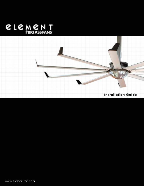
Element ®<br />
Installation Guide<br />
Installation Guide:<br />
<br />
Rev. I<br />
<br />
<br />
See p. ii.<br />
3187235<br />
<br />
<br />
Contact Information<br />
Manufacturing<br />
<br />
<br />
<br />
assfans.com<br />
Customer Service<br />
<br />
<br />
<br />
assfans.com<br />
Warranty Returns<br />
<br />
<br />
<br />
assfans.com<br />
<br />
<br />
<br />
<br />
assfans.com.au<br />
EU Authorized Representative<br />
<br />
<br />
<br />
<br />
<br />
<br />
<strong>Ass</strong> Fan Company. The information contained<br />
assfans.com.<br />
May be covered by one or more of the following United States Patents:
ii<br />
ELEMENT ®<br />
IMPORTANT SAFETY INSTRUCTIONS<br />
READ AND SAVE THESE INSTRUCTIONS<br />
WARNING—TO REDUCE THE RISK OF FIRE, ELECTRIC SHOCK, OR INJURY TO PERSONS, OBSERVE THE FOLLOWING:<br />
a. <br />
b. When cutting or drilling into wall or ceiling, do not damage electrical wiring and other hidden utilities.<br />
CAUTION: The installation of a <strong>Big</strong> <strong>Ass</strong> <br />
and with any additional requirements set forth by the national electric code (NEC), ANSI/NFPA 70-2011, and all local codes.<br />
Code compliance is ultimately YOUR responsibility!<br />
WARNING: The fan controllers contain high voltage capacitors which take time to discharge after removal of mains supply.<br />
Before working on the fan controller, ensure isolation of mains supply from line inputs at the fan controller board (L1, L2/N).<br />
Wait three minutes for capacitors to discharge to safe voltage levels. Failure to do so may result in personal injury or death.<br />
CAUTION: Exercise caution and common sense when powering the fan. Do not connect the fan to a damaged or hazardous<br />
power source. Do not attempt to resolve electrical malfunctions or failures on your own. Contact <strong>Big</strong> <strong>Ass</strong> <strong>Fans</strong> at 1-877-BIG-<br />
FANS if you have any questions regarding the electrical installation of this fan.<br />
Suitable for use with solid-state speed controls.<br />
<strong>Ass</strong> <strong>Fans</strong> must be installed with <strong>Big</strong> <strong>Ass</strong><br />
Fan supplied controllers that are marked (on their cartons) to indicate the suitability with this model. Other parts cannot be<br />
substituted.<br />
CAUTION: When service or replacement of a component in the fan requires the removal or disconnection of a safety device,<br />
the safety device is to be reinstalled or remounted as previously installed.<br />
<br />
from the power supply before servicing.<br />
WARNING—TO REDUCE THE RISK OF FIRE, ELECTRIC SHOCK, OR INJURY TO PERSONS, OBSERVE THE FOLLOWING:<br />
a. Use this unit only in the manner intended by the manufacturer. If you have questions, contact the manufacturer.<br />
b. Before servicing or cleaning unit, switch power off at service panel and lock the service disconnecting means to prevent<br />
power from being switched on accidentally. When the service disconnecting means cannot be locked, securely fasten a<br />
prominent warning device, such as a tag, to the service panel.<br />
CAUTION: Do not bend the airfoils when installing or servicing the fan. Do not insert foreign objects between rotating airfoils.<br />
WARNING: Stay alert, watch what you are doing, and use common sense when installing fans. Do not install fans if tired<br />
<br />
personal injury.<br />
CAUTION: The installation of this fan requires the use of some power tools. Follow the safety procedures found in the owner’s<br />
manual for each of these tools and do not use them for purposes other than those intended by the manufacturer.<br />
CAUTION: The <strong>Big</strong> <strong>Ass</strong> <strong>Fans</strong> product warranty will not cover equipment damage or failure that is caused by improper<br />
installation.<br />
CAUTION: Do NOT install the fan where it may come into direct contact with water unless the fan is labeled, “Suitable for use<br />
in wet locations.”<br />
FCC compliance statement<br />
<br />
These limits are designed to provide reasonable protection against harmful interference in a commercial installation. This equipment<br />
<br />
<br />
<br />
<br />
• Reorient or relocate the receiving antenna.<br />
• <br />
• <br />
• <br />
<strong>Ass</strong> <strong>Fans</strong> could void the EMC compliance and<br />
negate your authority to operate the product.<br />
Industry Canada statement<br />
<br />
WWW.BIGASSFANS.COM ©2011 DELTA T CORP. DBA BIG ASS FAN CO. ALL RIGHTS RESERVED
ELEMENT ®<br />
Contents<br />
General Information<br />
Important Safety Information ii<br />
Regulatory Compliance Information<br />
ii<br />
Introduction<br />
1<br />
About <strong>Big</strong> <strong>Ass</strong> <strong>Fans</strong> 1<br />
About This Fan 1<br />
Pre-Installation<br />
<br />
<br />
<br />
4<br />
4<br />
Fan Diagram 5<br />
6<br />
Mounting Structure:<br />
I-Beam<br />
Mounting Structure:<br />
Bar Joists<br />
7<br />
8<br />
9<br />
9<br />
<br />
<br />
11<br />
<br />
<br />
Hanging the Fan<br />
<br />
<br />
<br />
14<br />
15<br />
15<br />
Installing Airfoils<br />
16<br />
16<br />
16<br />
Installing Dome<br />
1. <strong>Ass</strong>emble Dome 17<br />
17<br />
17<br />
Installing Guy Wires<br />
18<br />
18<br />
18<br />
® 19<br />
19<br />
Electrical Installation<br />
Electrical Installation Safety <br />
<br />
<br />
Delta Secondary<br />
<br />
<br />
Daisy Chaining<br />
Addressing<br />
<br />
<br />
<br />
<br />
<br />
<br />
<br />
Interfacing with<br />
Building Automation<br />
Systems<br />
<br />
<br />
<br />
<br />
<br />
<br />
WWW.BIGASSFANS.COM ©2011 DELTA T CORP. DBA BIG ASS FAN CO. ALL RIGHTS RESERVED
ELEMENT ®<br />
Operating the Fan<br />
<br />
Speed Selection Screen<br />
Active Fan Selection Screen<br />
Toggling Fan Direction<br />
<br />
<br />
<br />
<br />
<br />
Preventive Maintenance <br />
<br />
<br />
<br />
<br />
<br />
Troubleshooting<br />
General Troubleshooting <br />
Troubleshooting Fault Screens<br />
<br />
Warranty Return<br />
Instructions<br />
<strong>Big</strong> <strong>Ass</strong> <br />
Installers<br />
<br />
<br />
<br />
<br />
41<br />
Responsibility Agreement<br />
<br />
<br />
<br />
45<br />
WWW.BIGASSFANS.COM ©2011 DELTA T CORP. DBA BIG ASS FAN CO. ALL RIGHTS RESERVED
ELEMENT ®<br />
Introduction<br />
Thank you and congratulations on your purchase of a <strong>Big</strong> <strong>Ass</strong> <br />
<br />
<br />
<br />
assfans.com.<br />
Who we are and what we do<br />
<strong>Big</strong> <strong>Ass</strong> <br />
<br />
<br />
<strong>Ass</strong> <br />
business is done.<br />
About this fan<br />
1<br />
Fan<br />
diameter<br />
<br />
<br />
Input power<br />
<br />
<br />
16 ft (4.9 m) <br />
18 ft (5.5 m) <br />
<br />
<br />
<br />
Maximum amp<br />
<br />
<br />
<br />
<br />
<br />
<br />
<br />
<br />
<br />
<br />
Maximum<br />
RPM<br />
<br />
Fan weight*<br />
<br />
64 <br />
<br />
<br />
<br />
<br />
<br />
<br />
<br />
<br />
WWW.BIGASSFANS.COM ©2011 DELTA T CORP. DBA BIG ASS FAN CO. ALL RIGHTS RESERVED
2<br />
What’s in the box<br />
ELEMENT ®<br />
Pre-Installation<br />
CAUTION: Do not remove the motor from its protective packaging prior to hanging it!<br />
CAUTION: To prevent damage, avoid contact with the printed circuit board located on the bottom of the fan!<br />
CAUTION: If you ordered multiple fans, be sure to keep the components of each fan together.<br />
<br />
<br />
<br />
<br />
<strong>Ass</strong> <br />
Note: Dashed lines indicate internal boxes. Drawings below are not to scale.<br />
Main Box<br />
<br />
<br />
<br />
<br />
<br />
Test Cable<br />
(4) Dome Clip<br />
Dome Retainer<br />
<br />
<br />
<br />
Center Cap<br />
<br />
<br />
<br />
Dome 1<br />
Trim Accessory<br />
Dome Retainer<br />
<br />
Extension<br />
Tube Box<br />
Airfoil Box<br />
<br />
Airfoil<br />
<br />
<br />
Retainer<br />
<br />
1. <br />
WWW.BIGASSFANS.COM ©2011 DELTA T CORP. DBA BIG ASS FAN CO. ALL RIGHTS RESERVED
Parts included<br />
ELEMENT ®<br />
<br />
3<br />
CAUTION: The components located on the bottom of the main fan unit are fragile and include sensitive electronics. Do not<br />
remove the assembly from its protective packaging prior to hanging it from the extension tube!<br />
<br />
Hardware<br />
Extension Tube Hardware<br />
<br />
<br />
<br />
Winglet Hardware<br />
<br />
Mounting<br />
<br />
<br />
<br />
<br />
<br />
Safety Cable 1<br />
Beam Clip Hardware<br />
<br />
<br />
<br />
Access Door Hardware 1<br />
<br />
Main Fan Unit Hardware<br />
<br />
<br />
<br />
Airfoil Hardware<br />
<br />
<br />
<br />
<br />
Lower Safety Cable Hardware<br />
<br />
<br />
Dome Retainer Hardware 3<br />
<br />
<br />
Airfoils<br />
<br />
<br />
<br />
Retainer<br />
Wall Controller<br />
Dome 3<br />
Trim<br />
Dome 4<br />
(4) Dome<br />
Clip<br />
Dome<br />
Retainer<br />
Dome<br />
<br />
Center<br />
Cap<br />
Trim<br />
Accessory<br />
<br />
<br />
<br />
1. <br />
<br />
The components located on the bottom of the main fan unit are fragile and include sensitive electronics. Do not remove the assembly from its<br />
<br />
<strong>Ass</strong> <strong>Fans</strong> does not recommend installing a light module.<br />
4. <br />
WWW.BIGASSFANS.COM ©2011 DELTA T CORP. DBA BIG ASS FAN CO. ALL RIGHTS RESERVED
4<br />
Tools needed<br />
ELEMENT ®<br />
<br />
<strong>Big</strong> <strong>Ass</strong> <br />
<br />
Mechanical Installation:<br />
<br />
Standard Socket and Ratchet Set<br />
<br />
<br />
<br />
Electrical Installation:<br />
<br />
<br />
<br />
<br />
<br />
<br />
Important weights<br />
Part<br />
<br />
<br />
<br />
<br />
<br />
Aluminum Dome<br />
<br />
Weight<br />
17 lbs (7.7 kg)<br />
15 lbs (9.1 kg)<br />
<br />
<br />
<br />
<br />
<br />
WWW.BIGASSFANS.COM ©2011 DELTA T CORP. DBA BIG ASS FAN CO. ALL RIGHTS RESERVED
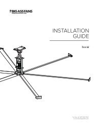
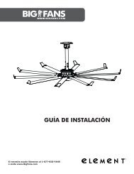
Fan diagram<br />
ELEMENT ®<br />
<br />
5<br />
A. Upper Yoke: Secures fan to mounting structure.<br />
B. Upper Safety Cable: Redundant safety feature that secures fan to<br />
mounting structure in the event of an accident.<br />
C. Extension Tube: <br />
D. Access Door: <br />
E. Main Fan Unit: <br />
(see p. 1 for more information).<br />
F. Airfoil: <br />
secure the airfoils to the fan hub.<br />
G. Winglet: <br />
H. Dome: Aluminum enclosure for components on underside of fan. Note:<br />
<br />
WWW.BIGASSFANS.COM ©2011 DELTA T CORP. DBA BIG ASS FAN CO. ALL RIGHTS RESERVED
6<br />
Preparing the work site<br />
ELEMENT ®<br />
<br />
CAUTION: Mount fan only to an angle iron or I-beam.<br />
<br />
• Element ® <br />
<br />
• <strong>Big</strong> <strong>Ass</strong> <br />
<br />
<br />
I-Beam<br />
Angle Iron<br />
• <br />
<br />
• <br />
Safety requirement<br />
Clearance<br />
Blade height<br />
Minimum distances<br />
<br />
<br />
<br />
<br />
Fan spacing<br />
<br />
<br />
<br />
<br />
• <br />
<br />
• <br />
• <br />
of torque during operation.<br />
• <strong>Ass</strong> <strong>Fans</strong> recommends that the fan be mounted according to the<br />
<br />
– The fan should be mounted outside of the clearances recommended by the manufacturer of the heater and at a height equal to or<br />
above the shielding on the heating element.<br />
– The controller must be mounted on the opposite side of the heater.<br />
– <br />
manufacturer of the heater and the controller must be remotely mounted.<br />
• <br />
<br />
WWW.BIGASSFANS.COM ©2011 DELTA T CORP. DBA BIG ASS FAN CO. ALL RIGHTS RESERVED
ELEMENT ®<br />
Mounting Structure: I-Beam<br />
7<br />
<strong>Big</strong> <strong>Ass</strong> <strong>Fans</strong> should only be hung from an I-beam or bar joists. See the following page for bar joist mounting<br />
instructions. Consult a structural engineer for installation methods not covered in this manual.<br />
WARNING: The fan should not be installed unless the structure on which the fan is to be mounted is of sound<br />
construction, undamaged, and capable of supporting the loads of the fan and the method of attachment to the structure.<br />
A structural engineer should verify that the structure is adequate prior to fan installation. Verifying the stability of the<br />
mounting structure is the sole responsibility of the customer and/or end user, and <strong>Big</strong> <strong>Ass</strong> <strong>Fans</strong> hereby expressly<br />
disclaims any liability arising therefrom, or arising from the use of any materials or hardware other than those supplied by<br />
<strong>Big</strong> <strong>Ass</strong> <br />
CAUTION: It is not recommended to mount a <strong>Big</strong> <strong>Ass</strong> Fan from a fabricated I-beam.<br />
CAUTION: Install the spacers <br />
the spacer are closer to one side than the other. Make sure this side is facing the I-beam.<br />
CAUTION: Ensure the mounting location will not expose the fan to direct contact with water unless the fan is labeled,<br />
“Suitable for use in wet locations.”<br />
1. Attach upper yoke (to I-beam)<br />
<br />
<br />
40 ft·lb (54.2 N·m) using a torque<br />
socket.<br />
Proceed to “Hanging the Fan” (p. 13).<br />
Beam Clip Hardware (BAF-Supplied):<br />
a. <br />
b. <br />
c. <br />
d. <br />
e. <br />
Small Upper Yoke<br />
<br />
I-beam<br />
<br />
<br />
<br />
<br />
<br />
<br />
<br />
Upper yoke<br />
mounting holes<br />
Inner holes<br />
<br />
Outer holes<br />
outer holes<br />
middle holes<br />
inner holes<br />
Upper Yoke<br />
(top view)<br />
Side View<br />
Large Upper Yoke<br />
<br />
I-beam<br />
<br />
<br />
<br />
<br />
<br />
<br />
<br />
Upper yoke<br />
mounting holes<br />
Inner holes<br />
<br />
Outer holes<br />
a<br />
b<br />
d<br />
e<br />
b<br />
c<br />
WWW.BIGASSFANS.COM ©2011 DELTA T CORP. DBA BIG ASS FAN CO. ALL RIGHTS RESERVED
8<br />
ELEMENT ®<br />
Mounting Structure: Bar Joists<br />
If you are installing the fan to an I-beam and have attached the upper yoke, proceed to “Hanging the Fan” (p. 13).<br />
WARNING: The fan should not be installed unless the structure on which the fan is to be mounted is of sound<br />
construction, undamaged, and capable of supporting the loads of the fan and the method of attachment to the structure.<br />
A structural engineer should verify that the structure is adequate prior to fan installation. Verifying the stability of the<br />
mounting structure is the sole responsibility of the customer and/or end user, and <strong>Big</strong> <strong>Ass</strong> <strong>Fans</strong> hereby expressly<br />
disclaims any liability arising therefrom, or arising from the use of any materials or hardware other than those supplied by<br />
<strong>Big</strong> <strong>Ass</strong> <br />
WARNING: Never use beam clamps when mounting the fan to angle irons! Beam clamps are only intended for I-beam<br />
installations.<br />
CAUTION: Do not install the fan from a single purlin, truss, or bar joist.<br />
CAUTION: Unsupported angle iron spans should not exceed 12 ft (3.7 m).<br />
CAUTION: The angle irons must be fastened to the roof structure at each end.<br />
CAUTION: Ensure the mounting location will not expose the fan to direct contact with water unless the fan is labeled,<br />
“Suitable for use in wet locations.”<br />
1. Select proper angle irons<br />
<br />
<br />
Angle iron span<br />
<br />
Minimum angle iron dimensions<br />
<br />
Number of angle<br />
irons needed<br />
<br />
<br />
4 1<br />
1. <br />
Angle Iron Side View<br />
(see table for dimensions)<br />
Height<br />
Width<br />
Thickness<br />
6’ (1.8m) or less<br />
over 6’ (1.8m) - 8’ (2.4m)<br />
over 8’ (2.4m) - 12’ (3.7m)<br />
WWW.BIGASSFANS.COM ©2011 DELTA T CORP. DBA BIG ASS FAN CO. ALL RIGHTS RESERVED
ELEMENT ®<br />
<br />
9<br />
2. Pre-drill angle irons<br />
<br />
<br />
<br />
<br />
Ø 9/16" (1.4cm)<br />
A<br />
1/2 A<br />
5 3/8” (13.7cm)<br />
distance between roof<br />
structure mounting points<br />
3. Secure angle irons (if span is longer than 8 ft)<br />
If the angle iron span is 8 ft (2.4 m) or less, proceed to step 4a on the following page.<br />
<br />
<br />
of four angle irons.<br />
<br />
Align the angle irons to each other and tighten the bolts to 40 ft·lb (54.2 N·m) socket.<br />
<br />
Proceed to step 4b.<br />
Grade 8 Hardware (Customer-Supplied):<br />
a. <br />
b. <br />
c. <br />
c<br />
b<br />
b<br />
a<br />
Side View<br />
WWW.BIGASSFANS.COM ©2011 DELTA T CORP. DBA BIG ASS FAN CO. ALL RIGHTS RESERVED
10<br />
ELEMENT ®<br />
<br />
4a. Fasten single angle irons to roof structure mounting points<br />
If the angle iron span is greater than 8 ft (2.4 m) and requires double angle irons, proceed to step 4b.<br />
Do not<br />
<br />
Proceed to step 5.<br />
Grade 8 Hardware (Customer-Supplied):<br />
a. <br />
b. <br />
c. <br />
d. <br />
Square Washer<br />
3”<br />
(7.6 cm)<br />
Ø 9/16”<br />
(1.4 cm)<br />
3”<br />
(7.6 cm)<br />
a<br />
b<br />
Thickness:<br />
1/4” (6 mm)<br />
c<br />
b<br />
d<br />
WWW.BIGASSFANS.COM ©2011 DELTA T CORP. DBA BIG ASS FAN CO. ALL RIGHTS RESERVED
ELEMENT ®<br />
<br />
11<br />
4b. Fasten double angle irons to roof structure mounting points<br />
<br />
<br />
<br />
Grade 8 Hardware (Customer-Supplied):<br />
a. <br />
b. <br />
c. <br />
d. <br />
Square Washer<br />
3”<br />
(7.6 cm)<br />
a<br />
Ø 9/16”<br />
(1.4 cm)<br />
3”<br />
(7.6 cm)<br />
b<br />
Thickness:<br />
1/4” (6 mm)<br />
c<br />
b<br />
d<br />
WWW.BIGASSFANS.COM ©2011 DELTA T CORP. DBA BIG ASS FAN CO. ALL RIGHTS RESERVED
12<br />
ELEMENT ®<br />
<br />
5. Attach upper yoke (to angle irons)<br />
<br />
<br />
Tighten the bolts to 40 ft·lb (54.2 N·m) using a <br />
Beam Clip Hardware (BAF-Supplied):<br />
a. <br />
b. <br />
c. <br />
10 7/8" (27.6cm) 15 5/8" (39.7cm)<br />
Small Upper Yoke<br />
13 1/4’’ (33.7cm) x<br />
9 5/8” (24.4cm)<br />
Large Upper Yoke<br />
(Optional)<br />
18’’(45.7cm) x<br />
9 5/8”(24.4cm)<br />
<br />
Side View<br />
a<br />
b<br />
b<br />
c<br />
WWW.BIGASSFANS.COM ©2011 DELTA T CORP. DBA BIG ASS FAN CO. ALL RIGHTS RESERVED
ELEMENT ®<br />
Hanging the Fan<br />
13<br />
1. Attach extension tube (to upper yoke)<br />
<br />
<br />
<br />
Tighten the bolts to 40 ft·lb (54.2 N·m)<br />
<br />
Extension Tube Hardware:<br />
a. <br />
b. <br />
c. <br />
a<br />
b<br />
b<br />
c<br />
2. Install trim accessory<br />
<br />
<br />
Ceiling<br />
<br />
Retaining Clip<br />
Trim Accessory<br />
WWW.BIGASSFANS.COM ©2011 DELTA T CORP. DBA BIG ASS FAN CO. ALL RIGHTS RESERVED
14<br />
ELEMENT ®<br />
<br />
3. Secure upper safety cable<br />
The safety cable is a crucial part of the fan and must be installed correctly. If you have questions, call Customer Service<br />
at 1-877-BIG-FANS for assistance.<br />
<br />
<br />
the shackle should be on the topside of the I-beam or angle iron. Securely tighten the shackle.<br />
I-Beam Mount<br />
Shackle<br />
Angle Iron Mount<br />
WWW.BIGASSFANS.COM ©2011 DELTA T CORP. DBA BIG ASS FAN CO. ALL RIGHTS RESERVED
ELEMENT ®<br />
<br />
15<br />
4. Attach main fan unit (to extension tube)<br />
Do not discard the main fan unit packaging and foam. It should be used if the fan is ever moved or relocated.<br />
CAUTION: Do not remove the motor from its protective packaging<br />
prior to hanging it!<br />
CAUTION: To prevent damage, avoid contact with the printed<br />
circuit board located on the bottom of the fan!<br />
c<br />
b<br />
b<br />
a<br />
CAUTION: The main fan unit is heavy. Use care when raising it.<br />
<br />
<br />
<br />
Tighten the bolts to 20 ft·lb (27.1 N·m)<br />
<br />
Lower Safety Cable<br />
<br />
<br />
Main Fan Unit Hardware:<br />
a. <br />
b. <br />
c. <br />
5. Secure lower safety cable<br />
<strong>Big</strong> <strong>Ass</strong> <strong>Fans</strong> recommends completing electrical installation (p. 20) and testing the connections before installing the<br />
airfoils.<br />
CAUTION: When securing the lower safety cable, be careful not to pinch any electrical wiring that may be routed through<br />
the extension tube.<br />
<br />
<br />
<br />
<br />
<br />
Tighten the bolt to 20 ft·lb (27.1 N·m)<br />
a<br />
b<br />
Access<br />
Door<br />
Lower Safety Cable Hardware:<br />
a. <br />
b. <br />
WWW.BIGASSFANS.COM ©2011 DELTA T CORP. DBA BIG ASS FAN CO. ALL RIGHTS RESERVED
16<br />
ELEMENT ®<br />
Installing Airfoils<br />
<strong>Big</strong> <strong>Ass</strong> <strong>Fans</strong> recommends completing electrical installation (p. 20) and testing the connections before installing the<br />
airfoils.<br />
WARNING: Disconnect power to the fan before installing the airfoils.<br />
1. Attach winglets to airfoils<br />
<br />
<br />
<br />
Winglet Hardware:<br />
<br />
2. Position airfoils and trim<br />
<br />
3. Attach airfoils to main fan unit<br />
<br />
<br />
attached!<br />
Tighten the bolts along the outer perimeter to 29 ft·lb (39.3 N·m) and <br />
29 ft·lb (39.3 N·m) <br />
Airfoil Hardware:<br />
a. <br />
b. <br />
c. <br />
Airfoil Retainer<br />
c<br />
b<br />
<br />
<br />
b<br />
a<br />
WWW.BIGASSFANS.COM ©2011 DELTA T CORP. DBA BIG ASS FAN CO. ALL RIGHTS RESERVED
ELEMENT ®<br />
Installing Dome<br />
17<br />
WARNING: Disconnect power to the fan before installing the dome.<br />
<br />
1. <strong>Ass</strong>emble dome<br />
a<br />
<br />
<br />
<br />
<br />
Dome Clips<br />
Dome<br />
Dome Retainer Hardware (1):<br />
a. <br />
<br />
Dome Retainer<br />
2. Attach dome to static hub<br />
<strong>Big</strong> <strong>Ass</strong> <strong>Fans</strong> does not recommend installing a light module on the Element ® .<br />
<br />
<br />
<br />
<br />
<br />
<br />
Dome Retainer Hardware (2):<br />
<br />
3. Attach center cap to dome<br />
Snap the center cap into the dome retainer.<br />
WWW.BIGASSFANS.COM ©2011 DELTA T CORP. DBA BIG ASS FAN CO. ALL RIGHTS RESERVED
18<br />
ELEMENT ®<br />
Installing Guy Wires<br />
Guy wires may not be included in your fan order. They are intended to constrain the fan’s lateral movement and are<br />
only included with all fans that have extension tubes 4 ft (1.2 m) or longer.<br />
1. Attach guy wire brackets<br />
<br />
<br />
<br />
Note:<br />
<br />
® .<br />
Mounting Hardware (BAF-Supplied):<br />
a. <br />
b. <br />
b<br />
a<br />
2. Attach locking carabiners to guy wire brackets<br />
<br />
Securely tighten the carabiners.<br />
3. Attach beam clamp<br />
Attach the beam clamp to the mounting structure. <br />
a 45° <br />
<br />
<br />
<br />
<br />
c<br />
a<br />
b<br />
<br />
beam clamp.<br />
<br />
Guy Wire Hardware (BAF-Supplied):<br />
a. <br />
b. <br />
c. <br />
d. <br />
d<br />
WWW.BIGASSFANS.COM ©2011 DELTA T CORP. DBA BIG ASS FAN CO. ALL RIGHTS RESERVED
ELEMENT ®<br />
<br />
19<br />
4. Route guy wire through Gripple ®<br />
<br />
<br />
<br />
<br />
Gripple<br />
<br />
45°<br />
45°<br />
I-Beam<br />
I-Beam<br />
<br />
45°<br />
I-Beam<br />
I-Beam<br />
I-Beam<br />
I-Beam<br />
5. Install remaining guy wires<br />
Wire Rope Clip<br />
<br />
CAUTION: Over-tightening the guy wires could throw the fan off balance.<br />
<br />
<br />
<br />
<br />
and torque to 4.5 ft·lb (6.1 N·m)<br />
<br />
<br />
Gripple. <br />
WWW.BIGASSFANS.COM ©2011 DELTA T CORP. DBA BIG ASS FAN CO. ALL RIGHTS RESERVED
20<br />
ELEMENT ®<br />
Electrical Installation<br />
<br />
cause electric shock or damage the motor and the controller! Hazard of electrical shock!<br />
WARNING: The installation of a <strong>Big</strong> <strong>Ass</strong> <br />
and with any additional requirements set forth by the national electric code (NEC), ANSI/NFPA 70-2011, and all local codes.<br />
Code compliance is ultimately YOUR responsibility!<br />
WARNING: The fan controllers contain high voltage capacitors which take time to discharge after removal of mains supply.<br />
Before working on the fan controller, ensure isolation of mains supply from line inputs at the fan controller board (L1, L2/N).<br />
Wait three minutes for capacitors to discharge to safe voltage levels. Failure to do so may result in personal injury or death.<br />
CAUTION: The <strong>Big</strong> <strong>Ass</strong> <strong>Fans</strong> product warranty will not cover equipment damage or failure that is caused by improper<br />
installation.<br />
WARNING: Exercise caution and common sense when powering the fan. Do not connect the fan to a damaged or hazardous<br />
power source. Do not attempt to resolve electrical malfunctions or failures on your own. Contact <strong>Big</strong> <strong>Ass</strong> <strong>Fans</strong> at 1-877-BIG-<br />
FANS if you have any questions regarding the electrical installation of this fan.<br />
ATTENTION: If installing the fan in the United States, the fan must be installed per the following National Fire Protection<br />
<strong>Ass</strong>ociation (NFPA) guidelines:<br />
• The fan must be centered approximatelyween four adjacent sprinklers.<br />
• <br />
• <br />
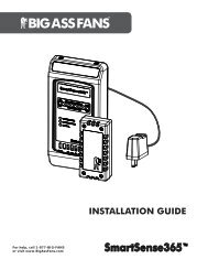
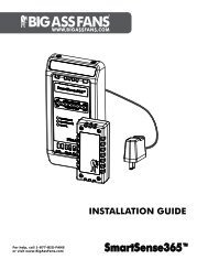
Mounting the wall controller<br />
To mount the wall controller,<br />
<br />
<br />
<br />
Wall Controller<br />
3 <br />
1/8” (7.9 cm)<br />
Mounting Plate<br />
<br />
5 )<br />
9/16” (14.1 cm)<br />
Depth: <br />
1 1/2” (3.8 cm)<br />
WWW.BIGASSFANS.COM ©2011 DELTA T CORP. DBA BIG ASS FAN CO. ALL RIGHTS RESERVED
Wiring connections<br />
ELEMENT ®<br />
Electrical Installation (cont.)<br />
21<br />
Route wiring through the top of the extension tube to the electronics mounting plate on the underside of the fan.<br />
CAUTION: To prevent damage, avoid contact with the printed circuit<br />
board located on the bottom of the fan!<br />
Wiring the motor<br />
<br />
• <br />
fan.<br />
• <br />
• <br />
• <br />
• <br />
Wiring the wall controller<br />
<br />
• <br />
the fan.<br />
• The required cable type is category 5 or 5E patch cable (not supplied). The<br />
<br />
<strong>Big</strong> <strong>Ass</strong> <strong>Fans</strong> recommends using a pre-made cable available at most<br />
electronics retailers. <br />
<br />
• <br />
• <br />
Delta secondary<br />
<br />
<br />
CAUTION: Care must be taken when connecting the Element ® fan to a three phase 240/120V Secondary as shown above.<br />
The Element fan controller relies on internal references made between each incoming phase and ground. To prevent<br />
damage to the fan controller, adhere to the the following recommendations:<br />
<br />
• 240V/120V Three Phase (Delta Secondary)<br />
<br />
is commonly referred to as a “Wild Leg” or “High Leg,”<br />
<br />
• 200V-250V Single phase <br />
<br />
“B” Phase<br />
240V<br />
208V<br />
“C” Phase<br />
120V 120V<br />
240V<br />
240V<br />
Neutral / Ground<br />
“A” Phase<br />
WWW.BIGASSFANS.COM ©2011 DELTA T CORP. DBA BIG ASS FAN CO. ALL RIGHTS RESERVED
ELEMENT ®<br />
22<br />
Electrical Installation (cont.)<br />
Wiring connections diagram<br />
J8- Main Power Connections<br />
• <br />
• <br />
• <br />
• <br />
• <br />
<br />
<br />
<br />
J19, J15- Wall Controller<br />
Connections<br />
J19<br />
J15<br />
<br />
<br />
<br />
<br />
• <br />
location<br />
• Cable Type: Category 5 or 5E<br />
• <br />
Attach wiring access door<br />
<br />
<br />
WWW.BIGASSFANS.COM ©2011 DELTA T CORP. DBA BIG ASS FAN CO. ALL RIGHTS RESERVED
Daisy chaining<br />
ELEMENT ®<br />
Electrical Installation (cont.)<br />
23<br />
Either port on the Element ® is acceptable for input or output. J15 and J19 can be treated as input or output at the<br />
discretion of the user; however, the connectors must be used accordingly on each fan. Route wiring through the top of the<br />
extension tube to the electronics mounting plate on the underside of the fan.<br />
<br />
<br />
<br />
standard.<br />
<br />
<br />
WWW.BIGASSFANS.COM ©2011 DELTA T CORP. DBA BIG ASS FAN CO. ALL RIGHTS RESERVED
24<br />
Addressing<br />
ELEMENT ®<br />
Electrical Installation (cont.)<br />
® fan motor assemblies. Earlier versions<br />
<br />
<br />
<br />
Rotary switch addressing<br />
<br />
<br />
The factory default address setting is 1.<br />
Dip switch addressing<br />
Position 4 is<br />
<br />
<br />
<br />
<br />
<br />
<br />
<br />
<br />
<br />
<br />
<br />
<br />
<br />
<br />
<br />
<br />
<br />
<br />
<br />
<br />
<br />
<br />
<br />
<br />
<br />
<br />
<br />
<br />
<br />
<br />
<br />
<br />
<br />
<br />
<br />
<br />
<br />
<br />
<br />
<br />
<br />
<br />
<br />
<br />
<br />
<br />
<br />
<br />
<br />
WWW.BIGASSFANS.COM ©2011 DELTA T CORP. DBA BIG ASS FAN CO. ALL RIGHTS RESERVED
ELEMENT ®<br />
Interfacing with Building Automation Systems<br />
® <br />
<br />
<br />
Wiring<br />
<br />
Terminal block J17 is a drive status relay contact, which will change upon drive fault conditions.<br />
25<br />
<br />
1 <br />
<br />
<br />
<br />
<br />
4 <br />
5 <br />
Signal Relay<br />
<br />
<br />
1<br />
<br />
4 1<br />
<br />
1 1<br />
S1<br />
6 <br />
7 <br />
8 <br />
9 <br />
<br />
11 <br />
Ambient Thermistor (-)<br />
<br />
<br />
14 <br />
15 <br />
16 <br />
17 Analog Output<br />
18 <br />
19 <br />
<br />
<br />
<br />
<br />
<br />
<br />
<br />
<br />
<br />
<br />
<br />
1 <br />
<br />
Common<br />
<br />
<br />
WWW.BIGASSFANS.COM ©2011 DELTA T CORP. DBA BIG ASS FAN CO. ALL RIGHTS RESERVED
ELEMENT ®<br />
26 <br />
0–10VDC analog speed reference<br />
Option one<br />
® <br />
recommended. Only ground cable shield at source end.<br />
N.O. Contact For Start/Stop<br />
(user supplied)<br />
RUN ENABLE (11)<br />
GND (10)<br />
SHLD(15)<br />
12<br />
24<br />
GND (23)<br />
0-10VDC (Z=20k) (22)<br />
+10VDC (21)<br />
SHLD (15)<br />
Potentiometer<br />
1-10k<br />
1<br />
13<br />
Option two<br />
<br />
cable shield at source end.<br />
N.O. Contact For Start/Stop<br />
(user supplied)<br />
12<br />
24<br />
+24VDC (typical)<br />
RUN ENABLE (11)<br />
GND (10)<br />
SHLD(15)<br />
0-10VDC (Z=20k) (22)<br />
DC+<br />
0-10VDC Out<br />
GND (23)<br />
SHLD<br />
DCCom<br />
Generic 0-10VDC Output<br />
Card / Device, user supplied<br />
1<br />
13<br />
WWW.BIGASSFANS.COM ©2011 DELTA T CORP. DBA BIG ASS FAN CO. ALL RIGHTS RESERVED
4–20mA analog speed reference<br />
ELEMENT ®<br />
<br />
27<br />
Option one<br />
® <br />
N.O. Contact For Start/Stop<br />
(user supplied)<br />
12<br />
24<br />
RUN ENABLE (11)<br />
GND (10)<br />
SHLD(15)<br />
4-20mA In (Z=100) (20)<br />
+15VDC (19)<br />
SHLD(15)<br />
1<br />
13<br />
Option two<br />
<br />
N.O. Contact For Start/Stop<br />
(user supplied)<br />
12<br />
24<br />
+24VDC (typical)<br />
RUN ENABLE (11)<br />
GND (10)<br />
SHLD(15)<br />
4-20mA In (Z=100) (20)<br />
DC+<br />
4-20mA<br />
Out<br />
Return / GND (15)<br />
DCCom<br />
Generic 4-20mA Output<br />
Card / Device, user supplied<br />
1<br />
13<br />
WWW.BIGASSFANS.COM ©2011 DELTA T CORP. DBA BIG ASS FAN CO. ALL RIGHTS RESERVED
ELEMENT ®<br />
28<br />
Operating the Fan<br />
Navigating the controller menu<br />
button. <br />
<br />
NEXT<br />
Power On, Fan Stopped<br />
#1<br />
Start / Stop<br />
#1<br />
12%<br />
Speed Selection Screen<br />
This screen unavailable if fan is off.<br />
#1<br />
56%<br />
#1<br />
100%<br />
See “Speed Selection Screen” for more<br />
information.<br />
NEXT<br />
ACTIVE FAN<br />
#4<br />
56%<br />
Active Fan Selection Screen<br />
See “Active Selection Screen” for more<br />
information<br />
ACTIVE FAN<br />
#5<br />
NEXT<br />
56%<br />
ACTIVE FAN<br />
#6<br />
56%<br />
WWW.BIGASSFANS.COM ©2011 DELTA T CORP. DBA BIG ASS FAN CO. ALL RIGHTS RESERVED
Navigating the controller menu<br />
ELEMENT ®<br />
Fan Operation (cont.)<br />
29<br />
NEXT<br />
Press<br />
Aux On<br />
to<br />
Turn Off<br />
Auxiliary<br />
Contact<br />
Selection<br />
Aux Off<br />
Press<br />
to<br />
Turn On<br />
Low Power Auxiliary Toggle<br />
See “Auxiliary Contact Selection<br />
Screen” for additional information.<br />
NEXT<br />
DIRECTION<br />
DIRECTION<br />
DIRECTION<br />
Fan Direction Toggle<br />
This screen unavailable if fan is off.<br />
See “Toggling Fan Direction” for<br />
additional information.<br />
WWW.BIGASSFANS.COM ©2011 DELTA T CORP. DBA BIG ASS FAN CO. ALL RIGHTS RESERVED
30<br />
Speed selection screen<br />
ELEMENT ®<br />
Fan Operation (cont.)<br />
<br />
<br />
NEXT<br />
#1<br />
12%<br />
#1 56%<br />
#1 100%<br />
Fan Diameter and RPM Chart<br />
Diameter Wall Pad 12-100%=<br />
8 ft (2,4m) 10-82 RPM<br />
10 ft (3,0m) 10-82 RPM<br />
12 ft (3,6m) 10-82 RPM<br />
14 ft (4,3m) 10-64 RPM<br />
16 ft (4,9m) 10-52 RPM<br />
18 ft (5,5m) 10-42 RPM<br />
20 ft (6,1m) 10-33 RPM<br />
WWW.BIGASSFANS.COM ©2011 DELTA T CORP. DBA BIG ASS FAN CO. ALL RIGHTS RESERVED
Active fan selection screen<br />
ELEMENT ®<br />
Fan Operation (cont.)<br />
31<br />
<br />
NEXT<br />
#4<br />
ACTIVE FAN<br />
33%<br />
#5<br />
ACTIVE FAN<br />
84%<br />
#9<br />
ACTIVE FAN<br />
26%<br />
About Active Fan Selection:<br />
The wall pad will control a maximum of 8 fans. If an invalid address is<br />
selected on the wall pad or there is a problem with the fan assigned to<br />
that particular number, a communications error will be reported on the<br />
upper left hand corner of the display .<br />
WWW.BIGASSFANS.COM ©2011 DELTA T CORP. DBA BIG ASS FAN CO. ALL RIGHTS RESERVED
32<br />
Toggling fan direction<br />
ELEMENT ®<br />
Fan Operation (cont.)<br />
NEXT<br />
DIRECTION<br />
DIRECTION<br />
DIRECTION<br />
green<br />
right arrow (correct rotation) or red left arrow (incorrect rotation)<br />
button to select the correct<br />
<br />
<br />
<br />
cooler monthslower speeds<br />
<br />
View From Under Fan<br />
WWW.BIGASSFANS.COM ©2011 DELTA T CORP. DBA BIG ASS FAN CO. ALL RIGHTS RESERVED
Toggling the auxiliary relays<br />
ELEMENT ®<br />
Fan Operation (cont.)<br />
33<br />
<br />
<br />
signals from the fan controller.<br />
NEXT<br />
Aux On<br />
Press<br />
to<br />
Turn Off<br />
Auxiliary<br />
Contact<br />
Selection<br />
Aux Off<br />
Press<br />
to<br />
Turn On<br />
<br />
<br />
NEXT<br />
#1<br />
25%<br />
WWW.BIGASSFANS.COM ©2011 DELTA T CORP. DBA BIG ASS FAN CO. ALL RIGHTS RESERVED
ELEMENT ®<br />
34 Preventive Maintenance<br />
<br />
appliance from the power supply before servicing.<br />
WARNING: Before servicing or cleaning unit, switch power off at service panel and lock the service disconnecting means<br />
to prevent power from being switched on accidentally. When the service disconnecting means cannot be locked, securely<br />
fasten a prominent warning device (such as a tag) to the service panel.<br />
WARNING: When service or replacement of a component in the fan requires the removal or disconnection of a safety<br />
device, the safety device is to be reinstalled or remounted as previously installed.<br />
<br />
<br />
Annual preventive maintenance<br />
<br />
<br />
1. <br />
slack as possible. The shackle should be securely tightened and located on the topside of the mounting structure.<br />
<br />
Ensure airfoils are secured to one another by airfoil retainers.<br />
4. Ensure all tightened.<br />
5. Ensure<br />
6. <br />
Ask about the <strong>Big</strong> <strong>Ass</strong> <br />
General preventive maintenance<br />
• <br />
<br />
<br />
• <br />
® <br />
<br />
• <br />
<br />
WARNING: Do not operate a fan with missing or damaged components.<br />
Please contact Customer Service at 1-877-BIG-FANS.<br />
2<br />
1<br />
2<br />
5<br />
3<br />
4<br />
WWW.BIGASSFANS.COM ©2011 DELTA T CORP. DBA BIG ASS FAN CO. ALL RIGHTS RESERVED
Annual Maintenance Checklist<br />
Fan Model: Fan Model: Fan Model:<br />
Serial #: Serial #: Serial #:<br />
Location: Location: Location:<br />
Date Initials Date Initials Date Initials
ELEMENT ®<br />
Troubleshooting<br />
37<br />
WARNING: When servicing or replacement of a component in the fan requires the removal or disconnection of a safety<br />
device, the safety device is to be reinstalled or remounted as previously installed.<br />
<br />
power supply before servicing.<br />
WARNING: TO REDUCE THE RISK OF FIRE, ELECTRIC SHOCK, OR INJURY TO PERSONS, OBSERVE THE FOLLOWING:<br />
a) Use this unit only in the manner intended by the manufacturer. If you have questions, contact the manufacturer.<br />
b) Before servicing or cleaning unit, switch power off at service panel and lock the service disconnecting means to<br />
prevent power from being switched on accidentally. When the service disconnecting means cannot be locked, securely<br />
fasten a prominent warning device, such as a tag, to the service panel.<br />
General troubleshooting<br />
Symptom<br />
<br />
Possible solution(s)<br />
<br />
green right arrow (correct<br />
rotation) or red left arrow (incorrect rotation) in the upper left-hand corner of the<br />
<br />
button to select the correct rotation<br />
<br />
<br />
Airfoil noise comes from airfoils that are<br />
<br />
<br />
<br />
<br />
<strong>Ass</strong> <br />
<br />
• <br />
• <br />
• <br />
• <br />
<br />
<br />
<br />
WWW.BIGASSFANS.COM ©2011 DELTA T CORP. DBA BIG ASS FAN CO. ALL RIGHTS RESERVED
38<br />
ELEMENT ®<br />
Troubleshooting (cont.)<br />
Troubleshooting fault screens<br />
Communication Error<br />
<br />
<br />
a communication error. For<br />
<br />
<br />
electronics mounting plate is in<br />
<br />
<br />
(S1) should be in the OFF<br />
<br />
the chain.<br />
Fan# 1<br />
Motor Fault<br />
Service<br />
Required<br />
PFC<br />
PFC- Motor Fault<br />
Contact Customer Service at<br />
<br />
Fan# 1<br />
Motor Fault<br />
Overcurrent<br />
Service<br />
Required<br />
Overcurrent- Motor Fault<br />
Contact Customer Service at<br />
<br />
Fan# 1<br />
Motor Fault<br />
Service<br />
Required<br />
Thermal<br />
Thermal- Motor Fault<br />
Contact Customer Service at<br />
<br />
Fan# 1<br />
Motor Fault<br />
Service<br />
Required<br />
Stall<br />
Stall- Motor Fault<br />
Turn the fan off and back<br />
<br />
contact Customer Service at<br />
<br />
Fan# 1<br />
Drive Fault<br />
Service<br />
Required<br />
Thermal<br />
Thermal- Drive Fault<br />
Contact Customer Service at<br />
<br />
Fan# 1<br />
Motor Fault<br />
Low AC Line<br />
Service<br />
Required<br />
Low AC Line- Motor Fault<br />
<br />
levels. Ensure supply voltage<br />
is adequate and restart the<br />
<br />
contact Customer Service at<br />
<br />
Fan# 1<br />
Imbalance<br />
Detected<br />
Correct the<br />
fault, then<br />
Reset System.<br />
Imbalance<br />
An imbalance condition occurs<br />
<br />
that there are no objects in the<br />
<br />
<br />
<br />
properly tightened. Turn the<br />
fan off and back on. If the fault<br />
<br />
<br />
WWW.BIGASSFANS.COM ©2011 DELTA T CORP. DBA BIG ASS FAN CO. ALL RIGHTS RESERVED
ELEMENT ®<br />
Warranty Return Instructions<br />
Congratulations on your purchase of a <strong>Big</strong> <strong>Ass</strong> ® fan to improve the quality of<br />
<br />
Replacement of products under warranty acknowledgment & return instructions<br />
<br />
<br />
<br />
<br />
<br />
<br />
<br />
<br />
<br />
<br />
receipt of the replacement item.<br />
Instructions for returning the original item<br />
1. <br />
<strong>Big</strong> <strong>Ass</strong> Fan Company<br />
<br />
<br />
<br />
39<br />
<br />
<br />
4. <br />
<br />
<br />
5. <br />
pickup location.<br />
<br />
<br />
<br />
<strong>Big</strong> <strong>Ass</strong> Fan Company<br />
WWW.BIGASSFANS.COM ©2011 DELTA T CORP. DBA BIG ASS FAN CO. ALL RIGHTS RESERVED
ELEMENT ®<br />
40 <br />
Warranty claim form instructions<br />
1. <br />
<br />
<strong>Ass</strong> <strong>Fans</strong> Customer<br />
Service.<br />
<br />
<br />
<br />
<br />
<br />
<br />
<br />
<br />
<br />
component (see Responsibility Agreement).<br />
<br />
at 800 Winchester Road, Lexington, KY 40505.<br />
a. <strong>Ass</strong><br />
<br />
b. both the packaging from the replacement part and the<br />
packing list and a return address label included inside this packaging to return the original part. If the original packaging and<br />
<br />
Note: The RMA# must appear on the outside of the box being returned. Items without an RMA# will not be accepted.<br />
c. <br />
<br />
d. <br />
<br />
4. <br />
<br />
<br />
<br />
WWW.BIGASSFANS.COM ©2011 DELTA T CORP. DBA BIG ASS FAN CO. ALL RIGHTS RESERVED
Warranty Claim Form<br />
<br />
<br />
<br />
<br />
assfans.com<br />
Name (print):<br />
Signature:<br />
Company:<br />
Shipping Address:<br />
City/State/ZIP:<br />
Phone:<br />
Items Returned:<br />
Fax:<br />
Date of<br />
Purchase:<br />
Reason(s) for Returning Item<br />
<br />
<strong>Ass</strong> Fan Company Customer Service<br />
Department. The RMA# must appear on the outside of the box being returned. Items without an RMA# will not be accepted.<br />
Date Replacement Parts<br />
Should Be Shipped (if known):<br />
<br />
<br />
scheduled installation.)<br />
<br />
(to be completed by <strong>Big</strong> <strong>Ass</strong> Fan Company)<br />
Acknowledged By:<br />
Date:<br />
RMA#:<br />
Authorized Truck Line(s):
To: <strong>Big</strong> <strong>Ass</strong> Fan Company<br />
Responsibility Agreement<br />
<br />
<br />
<br />
<br />
assfans.com<br />
<strong>Ass</strong> Fan<br />
<strong>Ass</strong> <br />
merchandise should be replaced at no cost under <strong>Big</strong> <strong>Ass</strong> <br />
The undersigned further agrees that if <strong>Big</strong> <strong>Ass</strong> Fan Company determines that this merchandise does not qualify under its stated<br />
<strong>Ass</strong> <br />
<br />
The undersigned agrees to ship to <strong>Big</strong> <strong>Ass</strong> <br />
merchandise replaced by <strong>Big</strong> <strong>Ass</strong> <br />
<br />
The undersigned further agrees that if said replaced merchandise has not been shipped to <strong>Big</strong> <strong>Ass</strong> <br />
<strong>Ass</strong> <br />
<br />
Signed:<br />
Title:<br />
For:<br />
<br />
Date:
Check-In Procedure<br />
(for <strong>Big</strong> <strong>Ass</strong> <br />
<br />
<br />
<br />
<br />
assfans.com<br />
ATTENTION: These items must be completed prior to any additional installation crew members entering jobsite or any<br />
installation material being unloaded.<br />
Date:<br />
Company:<br />
Address:<br />
Job Name:<br />
Purchase Order No.:<br />
City/State/ZIP:<br />
Contact Name:<br />
Phone:<br />
E-mail:<br />
**SEE THE FOLLOWING PAGE FOR NFPA 13 REGULATIONS**<br />
<br />
<br />
<br />
<br />
<br />
Time (please list the number of employees and total duration of jobs):<br />
<br />
<br />
<br />
<br />
<br />
Safety Rules and Regulations listed:<br />
<br />
<br />
Additional comments:
Check-In Procedure (cont.)<br />
(for <strong>Big</strong> <strong>Ass</strong> <br />
National Fire Protection <strong>Ass</strong>ociation Standard<br />
<br />
<br />
<br />
• <br />
• <br />
• <br />
• <br />
<br />
I<strong>Ass</strong> <br />
please provide <br />
<br />
understanding and agreement of the installation to be completed.<br />
Customer Signature:<br />
Printed Name:<br />
Date:<br />
Contractor Signature:<br />
Printed Name:<br />
Date:<br />
<br />
<br />
<strong>Ass</strong><br />
<strong>Fans</strong>.
Close-Out Procedure<br />
(for <strong>Big</strong> <strong>Ass</strong> <br />
<br />
<br />
<br />
<br />
assfans.com<br />
Date:<br />
Company:<br />
Job Name:<br />
Address:<br />
Purchase Order No.:<br />
City/State/ZIP:<br />
Contact Name:<br />
Phone:<br />
E-mail:<br />
<br />
<br />
<br />
<br />
<br />
<br />
<br />
<br />
<br />
at check-in.<br />
<br />
<br />
<br />
<br />
<br />
Additional comments:
Close-Out Procedure (cont.)<br />
(for <strong>Big</strong> <strong>Ass</strong> <br />
National Fire Protection <strong>Ass</strong>ociation Standard<br />
<br />
<br />
<br />
• <br />
• <br />
• <br />
• <br />
<br />
NOTE: The customer’s initials are required as acknowledgement for the following instances:<br />
Return Trip Required – Additional Charges Apply (Customer not Ready/Lift Issues)<br />
Work Completed Outside Scope of Work (if applicable)<br />
<br />
Customer Understands and Approves Additional Charges As Explained in amount of $<br />
Other (Please Explain Below)<br />
(if applicable)<br />
I<strong>Ass</strong> <br />
please provide <br />
<br />
understanding and agreement of the installation to be completed.<br />
Customer Signature:<br />
Printed Name:<br />
Date:<br />
Contractor Signature:<br />
Printed Name:<br />
Date:<br />
<br />
<br />
<strong>Ass</strong><br />
<strong>Fans</strong>.
1001110101<br />
Rev. I<br />
2348 Innovation Drive, Lexington, KY 40511