MA/FS-1535 SERIES - toshiba tec europe
MA/FS-1535 SERIES - toshiba tec europe
MA/FS-1535 SERIES - toshiba tec europe

You also want an ePaper? Increase the reach of your titles
YUMPU automatically turns print PDFs into web optimized ePapers that Google loves.
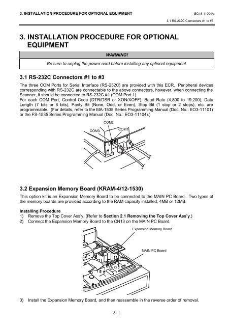
3. INSTALLATION PROCEDURE FOR OPTIONAL EQUIPMENT EO18-11004A3.1 RS-232C Connectors #1 to #33. INSTALLATION PROCEDURE FOR OPTIONALEQUIPMENTWARNING!Be sure to unplug the power cord before installing any optional equipment.3.1 RS-232C Connectors #1 to #3The three COM Ports for Serial Interface (RS-232C) are provided with this ECR. Peripheral devicescorresponding with RS-232C are connectable to the above connectors, however, when connecting theScanner, it should be connected to RS-232C #1 (COM Port 1).For each COM Port, Control Code (DTR/DSR or XON/XOFF), Baud Rate (4,800 to 19,200), DataLength (7 bits or 8 bits), Parity Bit (None, Odd, or Even), Stop Bit (1 stop or 2 stops), etc. areprogrammable. (For details, refer to the <strong>MA</strong>-<strong>1535</strong> Series Programming Manual (Doc. No.: EO3-11101)or the <strong>FS</strong>-<strong>1535</strong> Series Programming Manual (Doc. No.: EO3-11104).)COM2COM3COM13.2 Expansion Memory Board (KRAM-4/12-1530)This option kit is an Expansion Memory Board to be connected to the <strong>MA</strong>IN PC Board. Two types ofthe memory boards are provided according to the RAM capacity installed; 4MB or 12MB.Installing Procedure1) Remove the Top Cover Ass’y. (Refer to Section 2.1 Removing the Top Cover Ass’y.)2) Connect the Expansion Memory Board to the CN13 on the <strong>MA</strong>IN PC Board.Expansion Memory Board<strong>MA</strong>IN PC BoardCN133) Install the Expansion Memory Board, and then reassemble in the reverse order of removal.3- 1