Standard J-1 Manual - Macca's Vintage Aerodrome
Standard J-1 Manual - Macca's Vintage Aerodrome
Standard J-1 Manual - Macca's Vintage Aerodrome

You also want an ePaper? Increase the reach of your titles
YUMPU automatically turns print PDFs into web optimized ePapers that Google loves.
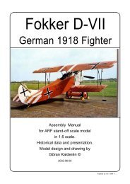
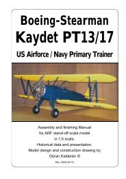
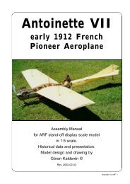
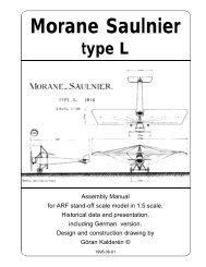
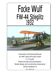
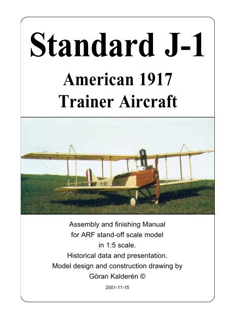
<strong>Standard</strong> J-1<br />
American 1917<br />
Trainer Aircraft<br />
Assembly and finishing <strong>Manual</strong><br />
for ARF stand-off scale model<br />
in 1:5 scale.<br />
Historical data and presentation.<br />
Model design and construction drawing by<br />
Göran Kalderén ©<br />
2001-11-15
STANDARD J-1<br />
Designed and built by the <strong>Standard</strong> Aircraft<br />
Company of Elizabeth, New Jersey in 1917<br />
and 1918. The <strong>Standard</strong> J-1 was used by the<br />
Aviation Section during World War I for primary<br />
flight instruction.<br />
In 1918 all <strong>Standard</strong>s equipped with Hall-Scott<br />
A7a engines were grounded due to a series of<br />
fires caused by hard landings or crashes and<br />
severe engine vibrations in flight breaking the<br />
flimsy fuel lines of the pressurized fuel system<br />
used on engines that powered them.<br />
<strong>Standard</strong> J1 ARF 2<br />
After the war many were converted by<br />
Curtiss to use OX-5 engines and were sold as<br />
”Curtiss-<strong>Standard</strong>s”.Re-engined with the<br />
Hispano-Suiza engine, the ”Hisso-<strong>Standard</strong>”<br />
became the aircraft of choice for barnstormers<br />
and air show operators. Because the cockpits<br />
were wider than that of the Jenny two people<br />
could be carried per flight, doubling the per flight<br />
revenue of the barnstorming pilot. The wider<br />
accomodations also made room for more cargo<br />
for prohibition era smugglers on ”midnight<br />
sightseeing trips”. The movie industri liked the<br />
The <strong>Standard</strong> J-1 in the US Airforce Museum<br />
in Dayton, Ohio, U.S.A. Our model is painted<br />
as this aircraft is displayed.<br />
Photos courtesy of the US Air Force Museum Photos courtesy of the US Air Force Museum
One <strong>Standard</strong> J-1, that is preserved in the Owls Head Transport Museum in Maine, U.S.A.<br />
<strong>Standard</strong> and it was used in numerous flicks. A<br />
"Hisso-<strong>Standard</strong>" was the aircraft flown by Robert<br />
Redford in the movie ”The Great Waldo Pepper”.<br />
The easiest ways to tell a <strong>Standard</strong> from<br />
a Curtiss Jenny is that the <strong>Standard</strong>’s wings<br />
have a slight sweepback and both cockpits are<br />
aft of the cabane struts as opposed to just the<br />
aft cockpit of the Jenny. The space between<br />
the wings on the <strong>Standard</strong> was a foot greater<br />
and the interplane struts were vertical instead<br />
of canted forward like the Jenny’s. Also the original<br />
Hall-Scott engine of the <strong>Standard</strong> used a<br />
vertical radiator placed in front of the pilot which<br />
kept him warm on cold days but was obviously<br />
a major hinderance to forward visibility.<br />
Aside from the Hall-Scott 4 cylinder en-<br />
gine and its inherent problems, the <strong>Standard</strong> J-<br />
1 was a rugged, reliable, stable and easy to fly<br />
aircraft for the period. It was produced by four<br />
manufacturers (<strong>Standard</strong>, Dayton-Wright,<br />
Fisher Body, and Wright Martin) and a total of<br />
1,601 J-1s were built.<br />
SPECIFICATIONS<br />
Span: 43 ft. 10 in. 13,15 m<br />
Length: 26 ft. 7 in. 7,98 m<br />
Height: 10 ft. 10 in. 3,25 m<br />
Weight: 2,100 lbs. loaded<br />
Dihedral both wings: 3°<br />
Sweepback both wings: 5°<br />
Engine: Hall-Scott A-4A of 100 hp.<br />
Max. speed: 72 mph.<br />
Endurance: 3 ½ hrs.<br />
The <strong>Standard</strong> J-1 in the US Airforce Museum<br />
in Dayton, Ohio, U.S.A. This aircraft is presently<br />
not avaialble for viewing.<br />
<strong>Standard</strong> J1 ARF 3<br />
Photos courtesy of the US Air Force Museum
<strong>Standard</strong> J1 with Hispano Suiza engine in the Garber restoration section of National Air and Space Museum,<br />
Washington DC., U.S.A.<br />
<strong>Standard</strong> J1 ARF 4
<strong>Standard</strong> J<br />
Wing Span: 42 ft 10 in (12.8 m)<br />
Length: 27 ft 2 in (8.2 m)<br />
Height: 10 ft 10 in (3.3 m)<br />
Dihedral both wings: 3°<br />
Sweepback both wings: 5°<br />
Engine: Hall-Scott A-4A of 100 hp<br />
<strong>Standard</strong> J1 ARF 5<br />
Photos courtesy of the US Air Force Museum
<strong>Standard</strong> J1 ARF 6<br />
The excellent quarterly<br />
magazine World War I<br />
Aeroplanes offers in their<br />
July 1980 (#80) issue a<br />
cover drawing. There is<br />
also extensive research<br />
data, a very detailed x-ray<br />
drawing by Jim Dunavent<br />
and and interesting historical<br />
description of the<br />
<strong>Standard</strong> J1.<br />
Below:<br />
Our model has the paintwork<br />
of the aircraft on<br />
display in the US Airforce<br />
Museum in Dayton Ohio,<br />
U.S.A.
The complete airframe before covering<br />
The Model<br />
We have chosen the scale of 1:5 rendering a<br />
model size that i easy to fly but also relatively easy<br />
to transport. Both the upper and the lower wing<br />
panels can be removed as an assembly, for<br />
transportation which gives relatively limited<br />
requirement for transportation size.<br />
The finished model is painted in 1918 livery<br />
and further detailing can be made as per<br />
documentation.<br />
Specification:<br />
Wingspan: 263 cm 105.2"<br />
Length: 160 cm 63.8"<br />
Weight: 6200 g 13lb. 9oz.<br />
Wing surface: 162 dm² 2511 sq”<br />
Wing load: 38 g/dm² 13 oz/sq’<br />
Engine 2-cycle .80 - 1.20<br />
Engine 4-cycle 1.20-1.50<br />
Covering and finish<br />
The model is covered and painted from the<br />
factory. When you have made changes in the fire<br />
wall and adapted the dummy engine to fit in line<br />
with the engine, you will have to cover the open<br />
wood areas with fuel proof paint.<br />
Installation of engine.<br />
We recommend that you don't overpower this<br />
model. It will fly happily with a 1.20 standard 4stroke<br />
engine. Our prototype was tried out with a<br />
Saito 1.20, 4-stroke engine, which gave more than<br />
ample thrust. The engine bearers have been<br />
adjusted for this size of engine.<br />
The engine is mounted upright justifying the<br />
need for adequate cooling.<br />
1. Drill the holes in the engine plywood<br />
bearers and fasten the engine with blind nuts on<br />
the underside of the plywood. Place the engine as<br />
close to the front as possible. The propeller should<br />
be approx 1/8" / 3mm) it front of the nose cowl.<br />
2. Drill the holes from the tank to the<br />
carburator, pressure tap and the filling cap.<br />
3. Install the engine and connect the throttle<br />
servo.<br />
4. Make cut outs in the dummy engine block<br />
so that this will fit in line with your engine. This<br />
"surgery" is executed by removing a little at the<br />
time and checking. When you are satisfied with<br />
the fit and openings, screw the dummy engine on<br />
to the engine mounts using 2 screws and washers.<br />
Make the additional necessary cut out in the top<br />
engine cowling.<br />
5. Reinstall the engine cowl using 4 #2 sheet<br />
metal screws.<br />
The Saito 1.20 is<br />
nicely blending<br />
into the dummy<br />
engine<br />
<strong>Standard</strong> J1 ARF 7
The dummengine<br />
before any<br />
trimming for the<br />
engine for flying<br />
Installation of servos, tank, battery and receiver.<br />
The aileron servo is installed behind the<br />
joystick in the servo support provided.<br />
The elevator servo and the rudder servo<br />
are installed in front of the rudder bar and joystick<br />
in the cockpit floor. The tank is positioned on the<br />
plywood engine mount and in line with and behind<br />
the engine.<br />
The throttle servo is installed behind the fire wall.<br />
The receiver and the battery pack are<br />
positioned under the tank in the compartment<br />
accesible through a hatch in the bottom of the<br />
fuselage.<br />
The switch can be mounted on the instrument<br />
panel in the front cockpit.<br />
1. Attach a ball link head to joystick and rudder<br />
bar in the appropriate holes. You may have to<br />
enlarge the holes to take the screw from the ball<br />
link (Dubro #189 set of 2).<br />
2. Install the servos for rudder and elevator<br />
and temporarily connect the servo arms to the ball<br />
links. Deflection for elevator is 20° up and down<br />
and for rudder 30° right and left..<br />
<strong>Standard</strong> J1 ARF 8<br />
The aileron<br />
servo is<br />
mounted<br />
on the<br />
cockpit<br />
floor<br />
in the<br />
tray specially<br />
built for this<br />
purpose<br />
The aileron<br />
control wires exit<br />
through the side of the fuselage<br />
3. Install and connect the throttle servo in the<br />
fashion you prefer.<br />
4. Install the tank in the available space on<br />
the plywood engine bearer behind the engine.<br />
5. Install the aileron servos in the servo tray<br />
in the cockpit The aileron connecting wires<br />
attaches to the servo arm as shoed in the sketch.<br />
Deflection of the ailerons should be 20° up and<br />
down.<br />
6. Install the radio switch on the dash board.<br />
7. Place the receiver and the battery pack in<br />
the compartment under the tank, wrapped in foam<br />
rubber and secure with rubber bands.<br />
Assembly of the <strong>Standard</strong> J-1<br />
All parts have been assembled at the factory<br />
and only disassembled for transportation.<br />
Rudder and elevator wires are factory<br />
adjusted but may need some tensioning
The servos<br />
for rudder<br />
and elevator<br />
are mounted<br />
inverted in the floor<br />
of the cockpit. Access<br />
through hatch in the bottom<br />
The throttle servo is<br />
mounted next to<br />
the tank,<br />
behind the<br />
fire wall<br />
The aileron interconnecting<br />
wire runs thhrough<br />
guides in the<br />
upper wing<br />
adjustment after a while. Aileron can be adjusted<br />
with the clevices connecting to the aileron horns.<br />
Assembly of wing panels<br />
1. Push the lower wing halves into the holes<br />
in the fuselage.<br />
2. Push the upper wing halves into the holes<br />
in the wing cabane. Connect the flying wires and<br />
the landing wires. Attach the flying wires in place.<br />
Attach the landing wires in place.<br />
3. Install the interplane struts. Note that the<br />
approx. 1/8" shorter struts fit in the front positions.<br />
Connect the strut cross bracing by clipping the<br />
kwick links in place.<br />
The wires from the aileron servo run from<br />
the fuselage to the pulleys on the underside of the<br />
upper wing. The upper aileron horns are connected<br />
with a wire running on top of the wing and joined<br />
in the center. The aileron control wires form a<br />
Turnbuckle for rigging<br />
The tailskid<br />
can be<br />
reached from<br />
under the<br />
stabilizer<br />
closed loop from the servo in the fuselage.<br />
Should you need to replace a wire, use the<br />
attachment method indicated in the picture. When<br />
crimping the cerulet (sleeve) use a flat plier or a<br />
crimping tool, press firmly and don't cut through<br />
the wire.<br />
Landing gear<br />
1. Install the landing gear in the holes in the<br />
fuselage and secure with crossbracing.<br />
2. Install the wheels on the shaft and secure<br />
with the stoppers.<br />
3.Lace rubber bands in the fashion shown in<br />
the sketch. This is a very efficient shock absorber.<br />
Balancing<br />
The center of gravity / balancing point<br />
should be approx. approx. 14 cm (5.5")<br />
measured from the leading edge on the upper<br />
wing. Make adjustments if necessary.<br />
<strong>Standard</strong> J1 ARF 9
What is in the box:<br />
The ARF kit contains the parts shown in the picture.<br />
All the parts are covered and painted. All the rigging<br />
5<br />
4<br />
3<br />
1. Fuselage with wing cabane and radiator<br />
2. Landing gear<br />
3. Scale wheels<br />
4. Dummy engine with mount<br />
5. Scale propeller<br />
6. Fin with rudder<br />
7. Stabilizer / elevator<br />
K&W<br />
Model<br />
Airplanes Inc.<br />
<strong>Standard</strong> J1 ARF 10<br />
2<br />
10<br />
1<br />
9<br />
10<br />
Flying<br />
The prototype was flown with a Saito 1.20<br />
4-stroke engine. Let the engine swing a 16x8<br />
propeller if possible. This gives better thrust and<br />
reduces sound to a more realistic level. Remember<br />
this is a slow flying aircraft.<br />
Flying characteristics are very forgiving<br />
and will fly happily on 2/3 throttle. Set the elevator<br />
at zero angle for the first flight but be prepared to<br />
give down elevator if the model climbs out too<br />
steep. During the initial take off run you have to<br />
compensate for the torque with right rudder but as<br />
the speed builds up the rudder is returned to<br />
neutrual. This model should fly of the ground and<br />
8<br />
wires are supplied in the correct lengths and need<br />
only to be clipped to their positions.<br />
8. Upper wing panels<br />
9. Lower wing panels<br />
10. Interplane struts<br />
11. Wires, turnbuckles and hardware for assembly<br />
(not shown)<br />
12. Assembly manual with scale<br />
documentation<br />
P.O.Box 1229, Cebu City Centrl. Postoffice<br />
Cebu City 6000, Philippines<br />
Visiting address:<br />
3343 Gun-Ob, Kinalumsan,<br />
Lapu-Lapu City 6015, PHILIPPINES<br />
Phone +63 32-340 0772, Cellular +63 917-3200 985<br />
Telefax +63 32-340 7131, E-mail: kwmairpl@gsilink.com<br />
Website http://www.kwmairpl.com.ph<br />
6<br />
12<br />
not be pulled. Once airborn the aircraft is as its full<br />
size prototype. Remember: climb or decent is<br />
controlled with the throttle, speed with the elevator.<br />
Start the turns with the rudder, then use up elevator.<br />
It will be necessary at this time to give opposite<br />
aileron to dampen the turn rate.<br />
The landing approach can be rather steep<br />
as per prototype but the flare out needs almost full<br />
up elevator. Get the tail down to maintain directional<br />
stability.<br />
Happy landings!<br />
7