Standard J-1 Manual - Macca's Vintage Aerodrome
Standard J-1 Manual - Macca's Vintage Aerodrome
Standard J-1 Manual - Macca's Vintage Aerodrome

Create successful ePaper yourself
Turn your PDF publications into a flip-book with our unique Google optimized e-Paper software.
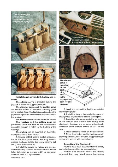
The dummengine<br />
before any<br />
trimming for the<br />
engine for flying<br />
Installation of servos, tank, battery and receiver.<br />
The aileron servo is installed behind the<br />
joystick in the servo support provided.<br />
The elevator servo and the rudder servo<br />
are installed in front of the rudder bar and joystick<br />
in the cockpit floor. The tank is positioned on the<br />
plywood engine mount and in line with and behind<br />
the engine.<br />
The throttle servo is installed behind the fire wall.<br />
The receiver and the battery pack are<br />
positioned under the tank in the compartment<br />
accesible through a hatch in the bottom of the<br />
fuselage.<br />
The switch can be mounted on the instrument<br />
panel in the front cockpit.<br />
1. Attach a ball link head to joystick and rudder<br />
bar in the appropriate holes. You may have to<br />
enlarge the holes to take the screw from the ball<br />
link (Dubro #189 set of 2).<br />
2. Install the servos for rudder and elevator<br />
and temporarily connect the servo arms to the ball<br />
links. Deflection for elevator is 20° up and down<br />
and for rudder 30° right and left..<br />
<strong>Standard</strong> J1 ARF 8<br />
The aileron<br />
servo is<br />
mounted<br />
on the<br />
cockpit<br />
floor<br />
in the<br />
tray specially<br />
built for this<br />
purpose<br />
The aileron<br />
control wires exit<br />
through the side of the fuselage<br />
3. Install and connect the throttle servo in the<br />
fashion you prefer.<br />
4. Install the tank in the available space on<br />
the plywood engine bearer behind the engine.<br />
5. Install the aileron servos in the servo tray<br />
in the cockpit The aileron connecting wires<br />
attaches to the servo arm as shoed in the sketch.<br />
Deflection of the ailerons should be 20° up and<br />
down.<br />
6. Install the radio switch on the dash board.<br />
7. Place the receiver and the battery pack in<br />
the compartment under the tank, wrapped in foam<br />
rubber and secure with rubber bands.<br />
Assembly of the <strong>Standard</strong> J-1<br />
All parts have been assembled at the factory<br />
and only disassembled for transportation.<br />
Rudder and elevator wires are factory<br />
adjusted but may need some tensioning