Standard J-1 Manual - Macca's Vintage Aerodrome
Standard J-1 Manual - Macca's Vintage Aerodrome
Standard J-1 Manual - Macca's Vintage Aerodrome

You also want an ePaper? Increase the reach of your titles
YUMPU automatically turns print PDFs into web optimized ePapers that Google loves.
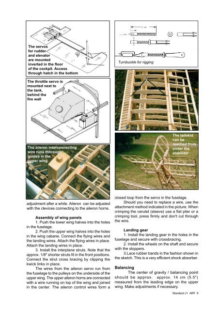
The servos<br />
for rudder<br />
and elevator<br />
are mounted<br />
inverted in the floor<br />
of the cockpit. Access<br />
through hatch in the bottom<br />
The throttle servo is<br />
mounted next to<br />
the tank,<br />
behind the<br />
fire wall<br />
The aileron interconnecting<br />
wire runs thhrough<br />
guides in the<br />
upper wing<br />
adjustment after a while. Aileron can be adjusted<br />
with the clevices connecting to the aileron horns.<br />
Assembly of wing panels<br />
1. Push the lower wing halves into the holes<br />
in the fuselage.<br />
2. Push the upper wing halves into the holes<br />
in the wing cabane. Connect the flying wires and<br />
the landing wires. Attach the flying wires in place.<br />
Attach the landing wires in place.<br />
3. Install the interplane struts. Note that the<br />
approx. 1/8" shorter struts fit in the front positions.<br />
Connect the strut cross bracing by clipping the<br />
kwick links in place.<br />
The wires from the aileron servo run from<br />
the fuselage to the pulleys on the underside of the<br />
upper wing. The upper aileron horns are connected<br />
with a wire running on top of the wing and joined<br />
in the center. The aileron control wires form a<br />
Turnbuckle for rigging<br />
The tailskid<br />
can be<br />
reached from<br />
under the<br />
stabilizer<br />
closed loop from the servo in the fuselage.<br />
Should you need to replace a wire, use the<br />
attachment method indicated in the picture. When<br />
crimping the cerulet (sleeve) use a flat plier or a<br />
crimping tool, press firmly and don't cut through<br />
the wire.<br />
Landing gear<br />
1. Install the landing gear in the holes in the<br />
fuselage and secure with crossbracing.<br />
2. Install the wheels on the shaft and secure<br />
with the stoppers.<br />
3.Lace rubber bands in the fashion shown in<br />
the sketch. This is a very efficient shock absorber.<br />
Balancing<br />
The center of gravity / balancing point<br />
should be approx. approx. 14 cm (5.5")<br />
measured from the leading edge on the upper<br />
wing. Make adjustments if necessary.<br />
<strong>Standard</strong> J1 ARF 9