Standard J-1 Manual - Macca's Vintage Aerodrome
Standard J-1 Manual - Macca's Vintage Aerodrome
Standard J-1 Manual - Macca's Vintage Aerodrome

You also want an ePaper? Increase the reach of your titles
YUMPU automatically turns print PDFs into web optimized ePapers that Google loves.
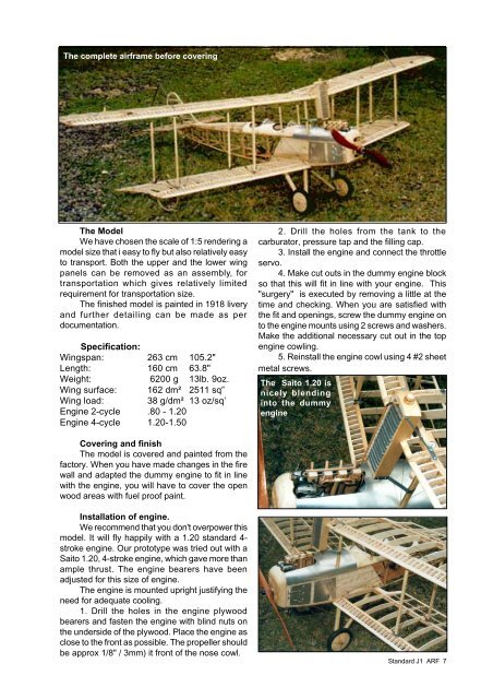
The complete airframe before covering<br />
The Model<br />
We have chosen the scale of 1:5 rendering a<br />
model size that i easy to fly but also relatively easy<br />
to transport. Both the upper and the lower wing<br />
panels can be removed as an assembly, for<br />
transportation which gives relatively limited<br />
requirement for transportation size.<br />
The finished model is painted in 1918 livery<br />
and further detailing can be made as per<br />
documentation.<br />
Specification:<br />
Wingspan: 263 cm 105.2"<br />
Length: 160 cm 63.8"<br />
Weight: 6200 g 13lb. 9oz.<br />
Wing surface: 162 dm² 2511 sq”<br />
Wing load: 38 g/dm² 13 oz/sq’<br />
Engine 2-cycle .80 - 1.20<br />
Engine 4-cycle 1.20-1.50<br />
Covering and finish<br />
The model is covered and painted from the<br />
factory. When you have made changes in the fire<br />
wall and adapted the dummy engine to fit in line<br />
with the engine, you will have to cover the open<br />
wood areas with fuel proof paint.<br />
Installation of engine.<br />
We recommend that you don't overpower this<br />
model. It will fly happily with a 1.20 standard 4stroke<br />
engine. Our prototype was tried out with a<br />
Saito 1.20, 4-stroke engine, which gave more than<br />
ample thrust. The engine bearers have been<br />
adjusted for this size of engine.<br />
The engine is mounted upright justifying the<br />
need for adequate cooling.<br />
1. Drill the holes in the engine plywood<br />
bearers and fasten the engine with blind nuts on<br />
the underside of the plywood. Place the engine as<br />
close to the front as possible. The propeller should<br />
be approx 1/8" / 3mm) it front of the nose cowl.<br />
2. Drill the holes from the tank to the<br />
carburator, pressure tap and the filling cap.<br />
3. Install the engine and connect the throttle<br />
servo.<br />
4. Make cut outs in the dummy engine block<br />
so that this will fit in line with your engine. This<br />
"surgery" is executed by removing a little at the<br />
time and checking. When you are satisfied with<br />
the fit and openings, screw the dummy engine on<br />
to the engine mounts using 2 screws and washers.<br />
Make the additional necessary cut out in the top<br />
engine cowling.<br />
5. Reinstall the engine cowl using 4 #2 sheet<br />
metal screws.<br />
The Saito 1.20 is<br />
nicely blending<br />
into the dummy<br />
engine<br />
<strong>Standard</strong> J1 ARF 7