Tecnai on-line help manual -- Alignments - UT Southwestern
Tecnai on-line help manual -- Alignments - UT Southwestern
Tecnai on-line help manual -- Alignments - UT Southwestern
- No tags were found...

You also want an ePaper? Increase the reach of your titles
YUMPU automatically turns print PDFs into web optimized ePapers that Google loves.
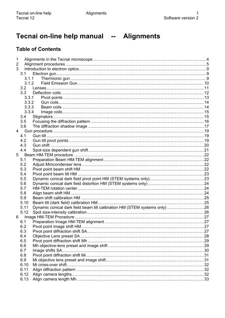
<str<strong>on</strong>g>Tecnai</str<strong>on</strong>g> <strong>on</strong>-<strong>line</strong> <strong>help</strong> <strong>Alignments</strong> 1<str<strong>on</strong>g>Tecnai</str<strong>on</strong>g> 12 Software versi<strong>on</strong> 2<str<strong>on</strong>g>Tecnai</str<strong>on</strong>g> <strong>on</strong>-<strong>line</strong> <strong>help</strong> <strong>manual</strong> --<strong>Alignments</strong>Table of C<strong>on</strong>tents1 <strong>Alignments</strong> in the <str<strong>on</strong>g>Tecnai</str<strong>on</strong>g> microscope................................................................................................42 Alignment procedures .......................................................................................................................53 Introducti<strong>on</strong> to electr<strong>on</strong> optics............................................................................................................93.1 Electr<strong>on</strong> gun...............................................................................................................................93.1.1 Thermi<strong>on</strong>ic gun ...................................................................................................................93.1.2 Field Emissi<strong>on</strong> Gun...........................................................................................................103.2 Lenses .....................................................................................................................................113.3 Deflecti<strong>on</strong> coils.........................................................................................................................123.3.1 Pivot points .......................................................................................................................133.3.2 Gun coils...........................................................................................................................143.3.3 Beam coils ........................................................................................................................143.3.4 Image coils........................................................................................................................153.4 Stigmators................................................................................................................................153.5 Focusing the diffracti<strong>on</strong> pattern ................................................................................................163.6 The diffracti<strong>on</strong> shadow image ..................................................................................................174 Gun procedure ................................................................................................................................194.1 Gun tilt .....................................................................................................................................194.2 Gun tilt pivot points...................................................................................................................194.3 Gun shift ..................................................................................................................................204.4 Spot-size dependent gun shift..................................................................................................215 Beam HM-TEM procedure ..............................................................................................................225.1 Preparati<strong>on</strong> Beam HM-TEM alignment.....................................................................................225.2 Adjust Minic<strong>on</strong>denser lens .......................................................................................................225.3 Pivot point beam shift HM ........................................................................................................225.4 Pivot point beam tilt HM ...........................................................................................................235.5 Dynamic c<strong>on</strong>ical dark field pivot point HM (STEM systems <strong>on</strong>ly)..............................................235.6 Dynamic c<strong>on</strong>ical dark field distorti<strong>on</strong> HM (STEM systems <strong>on</strong>ly) ...............................................245.7 HM-TEM rotati<strong>on</strong> center...........................................................................................................245.8 Align beam shift HM.................................................................................................................245.9 Beam shift calibrati<strong>on</strong> HM ........................................................................................................255.10 Beam tilt (dark field) calibrati<strong>on</strong> HM..........................................................................................255.11 Dynamic c<strong>on</strong>ical dark field beam tilt calibrati<strong>on</strong> HM (STEM systems <strong>on</strong>ly) ...............................265.12 Spot size-intensity calibrati<strong>on</strong>...................................................................................................266 Image HM-TEM Procedure .............................................................................................................276.1 Preparati<strong>on</strong> Image HM-TEM alignment ....................................................................................276.2 Pivot point image shift HM........................................................................................................276.3 Pivot point diffracti<strong>on</strong> shift SA...................................................................................................276.4 Objective Lens preset SA.........................................................................................................286.5 Pivot point diffracti<strong>on</strong> shift Mh ..................................................................................................296.6 Mh objective-lens preset and image shift .................................................................................296.7 Image shifts SA........................................................................................................................306.8 Pivot point diffracti<strong>on</strong> shift Mi....................................................................................................316.9 Mi objective lens preset and image shift...................................................................................316.10 Mi cross-over shift....................................................................................................................326.11 Align diffracti<strong>on</strong> pattern ............................................................................................................326.12 Align camera lengths................................................................................................................326.13 Align camera length Mh ...........................................................................................................33
<str<strong>on</strong>g>Tecnai</str<strong>on</strong>g> <strong>on</strong>-<strong>line</strong> <strong>help</strong> <strong>Alignments</strong> 2<str<strong>on</strong>g>Tecnai</str<strong>on</strong>g> 12 Software versi<strong>on</strong> 26.14 Image shift calibrati<strong>on</strong> HM........................................................................................................336.15 Diffracti<strong>on</strong> shift calibrati<strong>on</strong> HM..................................................................................................346.16 Beam shift - image shift calibrati<strong>on</strong> HM ....................................................................................346.17 Off-axis TV HM image alignment (<strong>on</strong>ly if off-axis TV installed) .................................................356.18 Off-axis TV diffracti<strong>on</strong> alignment (<strong>on</strong>ly if off-axis TV installed) ..................................................367 Beam LM Procedure .......................................................................................................................377.1 Preparati<strong>on</strong> Beam LM alignment..............................................................................................377.2 Pivot point beam shift LM .........................................................................................................377.3 Pivot point beam tilt LM............................................................................................................377.4 LM rotati<strong>on</strong> center ....................................................................................................................387.5 Align beam shift LM..................................................................................................................387.6 Beam shift calibrati<strong>on</strong> LM .........................................................................................................387.7 Beam tilt (dark field) calibrati<strong>on</strong> LM ..........................................................................................397.8 Spot size-intensity calibrati<strong>on</strong> LM .............................................................................................398 Image LM Procedure.......................................................................................................................418.1 Preparati<strong>on</strong> Image LM alignment .............................................................................................418.2 Pivot point image shift LM ........................................................................................................418.3 Pivot point diffracti<strong>on</strong> shift LM ..................................................................................................418.4 LM images ...............................................................................................................................428.5 Align LAD diffracti<strong>on</strong> pattern.....................................................................................................428.6 Image shift calibrati<strong>on</strong> LM ........................................................................................................448.7 Diffracti<strong>on</strong> shift calibrati<strong>on</strong> LAD ................................................................................................448.8 Beam shift - image shift calibrati<strong>on</strong> LM.....................................................................................458.9 Off-axis TV LM image alignment (<strong>on</strong>ly if off-axis TV installed)..................................................469 Beam Nanoprobe procedure ...........................................................................................................479.1 Preparati<strong>on</strong> Beam Nanoprobe alignment .................................................................................479.2 Pivot point beam shift Nanoprobe ............................................................................................479.3 Pivot point beam tilt Nanoprobe ...............................................................................................479.4 Dynamic c<strong>on</strong>ical dark field pivot point Nanoprobe (STEM systems <strong>on</strong>ly)..................................489.5 Dynamic c<strong>on</strong>ical dark field distorti<strong>on</strong> Nanoprobe (STEM systems <strong>on</strong>ly) ...................................489.6 Nanoprobe rotati<strong>on</strong> center........................................................................................................489.7 Align beam shift Nanoprobe .....................................................................................................499.8 Beam shift calibrati<strong>on</strong> Nanoprobe ............................................................................................509.9 Beam tilt (dark field) calibrati<strong>on</strong> Nanoprobe..............................................................................509.10 Dynamic c<strong>on</strong>ical dark field beam tilt calibrati<strong>on</strong> Nanoprobe (STEM systems <strong>on</strong>ly) ...................519.11 Spot size-intensity calibrati<strong>on</strong> Nanoprobe ................................................................................5110 Image Nanoprobe Procedure.......................................................................................................5210.1 SA objective lens preset Nanoprobe ........................................................................................5210.2 Mh objective lens preset Nanoprobe ........................................................................................5210.3 Mi objective lens preset Nanoprobe .........................................................................................5210.4 Align diffracti<strong>on</strong> pattern (Nanoprobe)........................................................................................5210.5 Beam shift - image shift calibrati<strong>on</strong> Nanoprobe ........................................................................5311 Stigmator Procedure....................................................................................................................5411.1 C<strong>on</strong>denser stigmator calibrati<strong>on</strong>...............................................................................................5411.2 Objective stigmator calibrati<strong>on</strong> .................................................................................................5411.3 Diffracti<strong>on</strong> stigmator calibrati<strong>on</strong> ................................................................................................5512 HM-STEM Procedure ..................................................................................................................5612.1 HM-STEM Preparati<strong>on</strong>.............................................................................................................5612.2 HM-STEM Objective / Intensity preset......................................................................................5612.3 HM-STEM Beam tilt pivot points...............................................................................................5712.4 HM-STEM Rotati<strong>on</strong> center .......................................................................................................5812.5 HM-STEM Beam-shift pivot points ...........................................................................................5912.6 HM-STEM Align diffracti<strong>on</strong> pattern...........................................................................................59
<str<strong>on</strong>g>Tecnai</str<strong>on</strong>g> <strong>on</strong>-<strong>line</strong> <strong>help</strong> <strong>Alignments</strong> 3<str<strong>on</strong>g>Tecnai</str<strong>on</strong>g> 12 Software versi<strong>on</strong> 212.7 HM-STEM Detector alignment .................................................................................................6012.8 HM-STEM Distorti<strong>on</strong> adjustment ..............................................................................................6212.9 HM-STEM Default rotati<strong>on</strong> .......................................................................................................6313 LM-STEM procedure ...................................................................................................................6513.1 LM-STEM Preparati<strong>on</strong> .............................................................................................................6513.2 LM-STEM Intensity preset........................................................................................................6513.3 LM-STEM Beam-shift pivot points............................................................................................6513.4 LM-STEM Align diffracti<strong>on</strong> pattern............................................................................................6613.5 LM-STEM Detector alignment ..................................................................................................6613.6 LM-STEM Distorti<strong>on</strong> adjustment...............................................................................................6813.7 LM-STEM Default rotati<strong>on</strong>........................................................................................................6914 HM-EFTEM procedure.................................................................................................................7014.1 HM-EFTEM Preparati<strong>on</strong>...........................................................................................................7014.2 HM-EFTEM Image-shift pivot points.........................................................................................7014.3 HM-EFTEM SA Diffracti<strong>on</strong>-shift pivot points.............................................................................7114.4 HM-EFTEM Mh Diffracti<strong>on</strong>-shift pivot points.............................................................................7114.5 HM-EFTEM Mi Diffracti<strong>on</strong>-shift pivot points..............................................................................7214.6 HM-EFTEM Mh Pre-alignment .................................................................................................7314.7 HM-EFTEM SA Image-shift pre-alignment ...............................................................................7314.8 HM-EFTEM SA Cross-over pre-alignment ...............................................................................7414.9 HM-EFTEM Mi Image-shift pre-alignment ................................................................................7414.10 HM-EFTEM Mi Cross-over pre-alignment ................................................................................7514.11 HM-EFTEM Mh Image shift......................................................................................................7514.12 HM-EFTEM SA Image shift ......................................................................................................7614.13 HM-EFTEM SA Cross-over correcti<strong>on</strong>......................................................................................7614.14 HM-EFTEM Mi Image shift.......................................................................................................7714.15 HM-EFTEM Mi Cross-over correcti<strong>on</strong>.......................................................................................7714.16 HM-EFTEM Camera-length pre-alignment ...............................................................................7814.17 HM-EFTEM Camera-length alignment .....................................................................................7815 LM-EFTEM Procedure.................................................................................................................8015.1 LM-EFTEM Preparati<strong>on</strong> ...........................................................................................................8015.2 LM-EFTEM Image-shift pivot points .........................................................................................8015.3 LM-EFTEM Diffracti<strong>on</strong>-shift pivot points ...................................................................................8015.4 LM-EFTEM Image-shift pre-alignment......................................................................................8115.5 LM-EFTEM Image-shift alignment............................................................................................8216 EFTEM Nanoprobe Procedure ....................................................................................................8316.1 SA objective lens preset EFTEM Nanoprobe ...........................................................................83
<str<strong>on</strong>g>Tecnai</str<strong>on</strong>g> <strong>on</strong>-<strong>line</strong> <strong>help</strong> <strong>Alignments</strong> 4<str<strong>on</strong>g>Tecnai</str<strong>on</strong>g> 12 Software versi<strong>on</strong> 21 <strong>Alignments</strong> in the <str<strong>on</strong>g>Tecnai</str<strong>on</strong>g> microscopeWhen a user logs into the microscope (by starting the <str<strong>on</strong>g>Tecnai</str<strong>on</strong>g> user interface), the microscope will recallthe necessary alignments. The microscope will follow a fixed procedure in restoring these alignments:• Look if a particular alignment exists for the user and, if so, load it.• If no user alignment exists, look if the alignment exists for the supervisor and, if so, load it.• If no supervisor alignment exists, look if the alignments exists for service and, if so, load it.• If no service alignment exists, look if the alignments exists for factory and, if so, load it.• If no factory alignments exists, load default settings.<strong>Alignments</strong> will exist for a particular user if the user has ever executed (part) of an alignment procedure.<strong>Alignments</strong> are as much as possible saved as a single parameter (except in the case of linkedparameters like pivot points or x-y values which are always kept together). A complete alignment for auser may thus c<strong>on</strong>sist of a mix of user-aligned values and values from other levels (supervisor, ...). Auser who has never d<strong>on</strong>e a gun alignment thus inherits the alignment from supervisor or higher. If thefilament (<strong>on</strong> LaB6 or W) or FEG tip has been changed and a new alignment d<strong>on</strong>e by the higher level, theuser will automatically get the new, correct alignment.When alignments are stored, they are stored completely (thus not <strong>on</strong>ly the user's own values). Up<strong>on</strong>restore the microscope will compare the values being reloaded. If the values are identical to the values inthe next higher existing level, the values are not stored in the user's own alignments.
<str<strong>on</strong>g>Tecnai</str<strong>on</strong>g> <strong>on</strong>-<strong>line</strong> <strong>help</strong> <strong>Alignments</strong> 5<str<strong>on</strong>g>Tecnai</str<strong>on</strong>g> 12 Software versi<strong>on</strong> 22 Alignment proceduresBelow is a list of alignment procedures. Some of the procedure steps may not be visible (dependent <strong>on</strong>user level 'user' or 'expert'). Some alignments like STEM, EFTEM and Lorentz may also be absent, sincethey depend <strong>on</strong> the hardware c<strong>on</strong>figurati<strong>on</strong> of the instrument.General notes:• In principle some alignments could be combined in single steps, thereby reducing the number ofsteps. In practice, it is then often forgotten to <strong>on</strong>e of the possible alignments, with the c<strong>on</strong>sequencethat <strong>on</strong>e alignment is then misaligned. Alignment procedure steps generally therefore perform <strong>on</strong>ly asingle alignment at a time.• In an alignment procedure some steps may be skipped when using Next and Previous. This is d<strong>on</strong>eto skip those alignments that are not sensitive to changes in operating c<strong>on</strong>diti<strong>on</strong>s (like pivot points),so that the procedure <strong>on</strong>ly follows the more often-used alignments. The visual indicati<strong>on</strong> whichalignments are skipped and which are executed, takes the form of two different ic<strong>on</strong>s in fr<strong>on</strong>t of thesubprocedure step. Where the ic<strong>on</strong> is a blue arrow <strong>on</strong> a white background, pointing to the right (intothe subprocedure) the subprocedure is not skipped. Where the arrow points down <strong>on</strong> a yellowbackground, the subprocedure is skipped.• Some alignment procedures start with a preparati<strong>on</strong> step. This step can be necessary becauseotherwise the entry point for the whole procedure would be in a 'skipped' subprocedure (see previouspoint).The following alignment procedures exist:Gun• Gun tilt• Gun tilt pivot point• Gun shift• Spot-size dependent gun shiftBeam HM-TEM• Preparati<strong>on</strong>• Minic<strong>on</strong>denser lens• Beam shift pivot point• Beam tilt pivot point• Dynamic c<strong>on</strong>ical dark field pivot point HM (STEM systems <strong>on</strong>ly)• Dynamic c<strong>on</strong>ical dark field distorti<strong>on</strong> HM (STEM systems <strong>on</strong>ly)• Rotati<strong>on</strong> center• Align beam shift• Beam shift calibrati<strong>on</strong>• Beam tilt calibrati<strong>on</strong>• Dynamic c<strong>on</strong>ical dark field beam tilt calibrati<strong>on</strong> HM (STEM systems <strong>on</strong>ly)• Spot size-intensity calibrati<strong>on</strong>• Coma-free amplitude• Coma-free pivot points• Coma-free alignment
<str<strong>on</strong>g>Tecnai</str<strong>on</strong>g> <strong>on</strong>-<strong>line</strong> <strong>help</strong> <strong>Alignments</strong> 6<str<strong>on</strong>g>Tecnai</str<strong>on</strong>g> 12 Software versi<strong>on</strong> 2Image HM-TEM• Preparati<strong>on</strong>• Image shift pivot point HM• Diffracti<strong>on</strong> shift pivot point SA• SA objective lens preset• Diffracti<strong>on</strong> shift pivot point Mh• Mh preset and alignment• SA magnificati<strong>on</strong>s alignment• Diffracti<strong>on</strong> shift pivot point Mi• Mi preset and alignment• Align diffracti<strong>on</strong> pattern• Align camera lengths• Image shift calibrati<strong>on</strong>• Diffracti<strong>on</strong> shift calibrati<strong>on</strong>• Beam shift - image shift calibrati<strong>on</strong>• Off-axis TV HM image alignment (<strong>on</strong>ly if off-axis TV installed)• Off-axis TV diffracti<strong>on</strong> alignment (<strong>on</strong>ly if off-axis TV installed)Beam LM• Preparati<strong>on</strong>• Beam shift pivot point• Beam tilt pivot point• Rotati<strong>on</strong> center• Align beam shift• Beam shift calibrati<strong>on</strong>• Beam tilt calibrati<strong>on</strong>• Spot size-intensity calibrati<strong>on</strong>Image LM• Preparati<strong>on</strong>• Image shift pivot point• Diffracti<strong>on</strong> shift pivot point• LM magnificati<strong>on</strong>s alignment• Align LAD pattern• Image shift calibrati<strong>on</strong>• Diffracti<strong>on</strong> shift calibrati<strong>on</strong>• Beam shift - image shift calibrati<strong>on</strong>• Off-axis TV LM image alignment (<strong>on</strong>ly if off-axis TV installed)
<str<strong>on</strong>g>Tecnai</str<strong>on</strong>g> <strong>on</strong>-<strong>line</strong> <strong>help</strong> <strong>Alignments</strong> 7<str<strong>on</strong>g>Tecnai</str<strong>on</strong>g> 12 Software versi<strong>on</strong> 2Beam Nanoprobe• Preparati<strong>on</strong>• Beam shift pivot point• Beam tilt pivot point• Dynamic c<strong>on</strong>ical dark field pivot point Nanoprobe (STEM systems <strong>on</strong>ly)• Dynamic c<strong>on</strong>ical dark field distorti<strong>on</strong> Nanoprobe (STEM systems <strong>on</strong>ly)• Rotati<strong>on</strong> center• Align beam shift• Beam shift calibrati<strong>on</strong>• Beam tilt calibrati<strong>on</strong>• Dynamic c<strong>on</strong>ical dark field beam tilt calibrati<strong>on</strong> Nanoprobe (STEM systems <strong>on</strong>ly)• Spot size-intensity calibrati<strong>on</strong>Image Nanoprobe• SA objective lens preset• Mh objective lens preset• Mi objective lens preset• Align diffracti<strong>on</strong> pattern• Beam shift - image shift calibrati<strong>on</strong>Stigmators• C<strong>on</strong>denser• C<strong>on</strong>denser stigmator shunt• Objective• Diffracti<strong>on</strong>HM-STEM• Preparati<strong>on</strong>• Objective / Intensity preset• Beam tilt pivot points• Rotati<strong>on</strong> center• Beam shift pivot points• Align diffracti<strong>on</strong> pattern• Detector alignment• Scan distorti<strong>on</strong> adjustment• Default scan rotati<strong>on</strong>• AC shunt• Calibrati<strong>on</strong>LM-STEM• Preparati<strong>on</strong>• Intensity preset• Beam shift pivot points• Align diffracti<strong>on</strong> pattern• Detector alignment• Scan distorti<strong>on</strong> adjustment• Default scan rotati<strong>on</strong>
<str<strong>on</strong>g>Tecnai</str<strong>on</strong>g> <strong>on</strong>-<strong>line</strong> <strong>help</strong> <strong>Alignments</strong> 8<str<strong>on</strong>g>Tecnai</str<strong>on</strong>g> 12 Software versi<strong>on</strong> 2EFTEM HM• Preparati<strong>on</strong>• HM Image-shift pivot points• SA Diffracti<strong>on</strong>-shift pivot points• Mh Diffracti<strong>on</strong>-shift pivot points• Mi Diffracti<strong>on</strong>-shift pivot points• Mh Pre-alignment• SA Image-shift pre-alignment• SA Cross-over correcti<strong>on</strong> pre-alignment• Mi Image shift pre-alignment• Mi Cross-over correcti<strong>on</strong> pre-alignment• Mh Image-shift alignment• SA Image-shift alignment• SA Cross-over correcti<strong>on</strong> alignment• Mi Image-shift alignment• Mi Cross-over correcti<strong>on</strong> alignment• Camera length pre-alignment• Camera length alignmentEFTEM LM• Preparati<strong>on</strong>• Image-shift pivot points• Diffracti<strong>on</strong>-shift pivot points• Image-shift pre-alignment• Image-shift alignmentEFTEM Nanoprobe• SA preset
<str<strong>on</strong>g>Tecnai</str<strong>on</strong>g> <strong>on</strong>-<strong>line</strong> <strong>help</strong> <strong>Alignments</strong> 9<str<strong>on</strong>g>Tecnai</str<strong>on</strong>g> 12 Software versi<strong>on</strong> 23 Introducti<strong>on</strong> to electr<strong>on</strong> opticsThe microscope c<strong>on</strong>sists essentially of three parts:1. The electr<strong>on</strong> gun where the beam is generated.2. The lenses, deflecti<strong>on</strong> coils and stigmators that make the image and project it <strong>on</strong> the screen.3. The projecti<strong>on</strong> chamber with <strong>on</strong>e or more types of electr<strong>on</strong> detectors to record images, diffracti<strong>on</strong>patterns, ... (plate camera, TV, ...).The first two topics will be covered in this secti<strong>on</strong>.3.1 Electr<strong>on</strong> gunThe electr<strong>on</strong> beam is generated in the electr<strong>on</strong> gun. Two basic types of gun can be distinguished: thethermi<strong>on</strong>ic gun and the field emissi<strong>on</strong> gun (FEG).• Thermi<strong>on</strong>ic guns are based <strong>on</strong> two types of filaments: tungsten (W) and lanthanum-hexaboride(LaB6) (cerium-hexaboride, CeB6, can also be used instead of LaB6; its performance is roughly thesame as that of LaB6). On modern instruments the different types of thermi<strong>on</strong>ic filaments can beused interchangeably.• The FEG employs either a (thermally-assisted) cold field emitter - as <strong>on</strong> the Philips EM 400-FEG - ora Schottky emitter - as <strong>on</strong> the more recent generati<strong>on</strong>s of FEG microscopes (CM20/CM200 FEG,CM30/CM300 FEG, <str<strong>on</strong>g>Tecnai</str<strong>on</strong>g> F20 and F30).3.1.1 Thermi<strong>on</strong>ic gunThe thermi<strong>on</strong>ic gun (so-called triode or self-biassing gun)c<strong>on</strong>sists of three elements: the filament (cathode), theWehnelt and the anode. The Wehnelt has a potential that ismore negative - the bias voltage - than the cathode itself. Thebias voltage is variable (c<strong>on</strong>trolled by the Emissi<strong>on</strong>parameter) and is used for c<strong>on</strong>trolling the emissi<strong>on</strong> from thefilament. A high bias voltage restricts the emissi<strong>on</strong> to a smallarea, thereby reducing the total emitted current, whilelowering the bias voltage increases the size of the emittingarea and thus the total emissi<strong>on</strong> current.The emitted electr<strong>on</strong>s that pass through the Wehnelt aperture are focused into across-over between the cathode and anode. This cross-over acts as the electr<strong>on</strong>source for the optics of the microscope.The size of the cross-over is determined by the type of filament, the electric field between cathode andanode and by the exit angles of the electr<strong>on</strong>s from the filament. At low bias voltages, electr<strong>on</strong>s areemitted from a larger area of the curved tip of the filament, causing a higher divergence of emissi<strong>on</strong>angles and thus a larger source size. Higher emissi<strong>on</strong> therefore not necessarily improves the brightness(a performance parameter of the emitter, measured in A/cm²srad). In additi<strong>on</strong>, higher emissi<strong>on</strong> increasesthe Coulomb interacti<strong>on</strong> between electr<strong>on</strong>s - the so-called Boersch effect - (some get accelerated, othersdecelerated) which increases the energy spread.
<str<strong>on</strong>g>Tecnai</str<strong>on</strong>g> <strong>on</strong>-<strong>line</strong> <strong>help</strong> <strong>Alignments</strong> 10<str<strong>on</strong>g>Tecnai</str<strong>on</strong>g> 12 Software versi<strong>on</strong> 23.1.2 Field Emissi<strong>on</strong> GunIn the case of a Field Emissi<strong>on</strong> Gun (abbreviated FEG), electr<strong>on</strong> emissi<strong>on</strong> is achieved in a different waythan with thermi<strong>on</strong>ic guns. Because a FEG requires a different gun design as well as much bettervacuum in the gun area (~10e-8 Pa instead of the ~10e-5 Pa necessary for thermi<strong>on</strong>ic guns), it is found<strong>on</strong>ly <strong>on</strong> dedicated microscopes (<str<strong>on</strong>g>Tecnai</str<strong>on</strong>g> F20, F30). The FEG c<strong>on</strong>sists of a small single-crystal tungstenneedle that is put in a str<strong>on</strong>g extracti<strong>on</strong> voltage (2-5 kV). In the case of a cold FEG or thermally-assistedcold FEG, the needle is so sharp that electr<strong>on</strong>s are extracted directly from the tip. For the Schottky FEG(as used <strong>on</strong> the <str<strong>on</strong>g>Tecnai</str<strong>on</strong>g> microscopes) a broader tip is used which has a surface layer of zirc<strong>on</strong>ia (ZrO 2 ).The zirc<strong>on</strong>ia lowers the work functi<strong>on</strong> of the tungsten (that is, it enhances electr<strong>on</strong> emissi<strong>on</strong>) and therebymakes it possible to use the broader tip. Unlike the thermi<strong>on</strong>ic gun, the FEG does not produce a smallcross-over directly below the emitter, but the electr<strong>on</strong> trajectories seemingly originate inside the tip itself,forming a virtual source of electr<strong>on</strong>s for the microscope.The FEG emitter is placed in a cap (suppressor) which prevents electr<strong>on</strong> emissi<strong>on</strong> from the shaft of theemitter and the heating filament (very similar to the Wehnelt of thethermi<strong>on</strong>ic gun). Electr<strong>on</strong> emissi<strong>on</strong> is regulated by the voltage <strong>on</strong> theextracti<strong>on</strong> anode. Underneath the extracti<strong>on</strong> anode of the FEG is asmall electrostatic lens, the gun lens. This lens is used to positi<strong>on</strong> thefirst cross-over after the gun in relati<strong>on</strong> to the beam-defining aperture(usually the C2 aperture). If the gun lens is str<strong>on</strong>g, the cross-over lieshigh above the aperture while a weak gun lens positi<strong>on</strong>s the crossoverclose to the aperture, giving a high current but at the expense ofaberrati<strong>on</strong>s <strong>on</strong> the beam. A str<strong>on</strong>g gun lens is therefore used where small, intense and low-aberrati<strong>on</strong>electr<strong>on</strong> probes are needed (diffracti<strong>on</strong>, analysis and scanning), while a weak gun lens is used whenhigh currents are important (TEM imaging). In the latter case, the beam is spread and the aberrati<strong>on</strong>s d<strong>on</strong>ot affect the area within the field of view.The high brightness of FEGs comes about because of two reas<strong>on</strong>s:1. The small size of the tip ensures that large numbers of electr<strong>on</strong>s are emitted from a small area (highA/cm²).2. The electr<strong>on</strong>s come out of the tungsten crystal with a very restricted range of emissi<strong>on</strong> angles (highA/srad). FEGs also have a low energy spread due to their low working temperature and emissi<strong>on</strong>geometry (small virtual source size, but much larger actual size of the emitting area).
<str<strong>on</strong>g>Tecnai</str<strong>on</strong>g> <strong>on</strong>-<strong>line</strong> <strong>help</strong> <strong>Alignments</strong> 11<str<strong>on</strong>g>Tecnai</str<strong>on</strong>g> 12 Software versi<strong>on</strong> 23.2 LensesThe lenses in electr<strong>on</strong> microscopes are electromagnetic lenses (the <strong>on</strong>ly excepti<strong>on</strong> being the gun lens inthe FEG instruments, which is an electrostatic lens). These lenses all c<strong>on</strong>sist of a coil, through which anelectrical current flows, and a magnetic circuit, which is a piece of magnetic alloy with a specific shape.The current flowing through the coil generates a magnetic field in the magnetic circuit. Where the circuitis interrupted (the gap), the magnetic field goes out into the vacuum and creates the lens field that isused for focusing the electr<strong>on</strong> beam. How the lens works is determined by the shape of the pole piece(the part of the magnetic circuit where the bore and gap are). Water flows through pipes to remove theheat generated by the electr<strong>on</strong> current in the lens coil.Changing the current through the lens coil changes the magnetic field and thus the strength of the lens.Although electromagnetic lenses and electr<strong>on</strong>s behave quite differently from light lenses and light, thegeneral principles of light optics can be applied and the electromagnetic lenses can be described forc<strong>on</strong>venience like the lenses of light optics.The TEM usually c<strong>on</strong>tains two c<strong>on</strong>denser lenses:• The first c<strong>on</strong>denser lens, or C1, determines the demagnificati<strong>on</strong> (size reducti<strong>on</strong>) of the electr<strong>on</strong>source <strong>on</strong>to the specimen and thus the spot size. Its c<strong>on</strong>trol is found under the spot size c<strong>on</strong>trol,which has 11 steps.• The sec<strong>on</strong>d c<strong>on</strong>denser lens, or C2, determines how str<strong>on</strong>gly the beam is focused <strong>on</strong>to the specimen.As a c<strong>on</strong>sequence it varies the intensity of the beam <strong>on</strong> the viewing screen. The C2 lens is c<strong>on</strong>trolledthrough the Intensity knob. Inside or close to the sec<strong>on</strong>d c<strong>on</strong>denser lens there is an aperture (thesec<strong>on</strong>d-c<strong>on</strong>denser or C2 aperture), which is used as the beam-defining aperture (it limits the amountof the beam c<strong>on</strong>vergence for a fully focused beam).The magnificati<strong>on</strong> system of the microscope c<strong>on</strong>sists of a set of five lenses: the objective, diffracti<strong>on</strong>,intermediate, projector 1 and projector 2 lenses. Except in low-magnificati<strong>on</strong> (LM) mode, the objectivelens is always the str<strong>on</strong>gest lens in the microscope, magnifying between about 20 and 50x, depending<strong>on</strong> the type of objective lens.The individual lenses of the magnificati<strong>on</strong> (or projector) system are not c<strong>on</strong>trolled directly by theoperator, but instead the microscope c<strong>on</strong>tains a number of magnificati<strong>on</strong>s for image and diffracti<strong>on</strong>mode, each with its own settings of the magnifying lenses. The <strong>on</strong>ly lenses that are c<strong>on</strong>trolled directly bythe operator are the objective lens (for focusing the image) and the diffracti<strong>on</strong> lens (for focusing thediffracti<strong>on</strong> pattern).In LM mode the objective lens is switched (nearly) off in order to achieve the smallest magnificati<strong>on</strong>s.With the objective lens off, the diffracti<strong>on</strong> lens is used for focusing the image. The electr<strong>on</strong>-opticalc<strong>on</strong>figurati<strong>on</strong> in LM is reversed with respect to the high-magnificati<strong>on</strong> range: the functi<strong>on</strong>s of the
<str<strong>on</strong>g>Tecnai</str<strong>on</strong>g> <strong>on</strong>-<strong>line</strong> <strong>help</strong> <strong>Alignments</strong> 12<str<strong>on</strong>g>Tecnai</str<strong>on</strong>g> 12 Software versi<strong>on</strong> 2objective and diffracti<strong>on</strong> lenses and stigmators switch as do the functi<strong>on</strong>s of the objective and selectedareaapertures.Lens and aperture functi<strong>on</strong>s in HM (objective lens <strong>on</strong>) and LM (objective lens off)High MagnLow MagnObj. lens Image focus Diffracti<strong>on</strong> (LAD) focusDiff. lens Diffracti<strong>on</strong> focus Image focusObj. aperture C<strong>on</strong>trast forming Area selecti<strong>on</strong>SA aperture Area selecti<strong>on</strong> C<strong>on</strong>trast formingObj. stigmator Image stigmati<strong>on</strong> Diffracti<strong>on</strong> stigmati<strong>on</strong>Diff. stigmator Diffracti<strong>on</strong> stigmati<strong>on</strong> Image stigmati<strong>on</strong>TWIN-type objective lensesMost <str<strong>on</strong>g>Tecnai</str<strong>on</strong>g> microscopes are equipped with a TWIN-type objective lens (the variants BioTWIN, TWIN,S-TWIN and U-TWIN). The lens design and the two resulting basic optical modes, the microprobe andnanoprobe modes, are discussed separately in more detail.3.3 Deflecti<strong>on</strong> coilsThroughout the microscope, the path followed by the electr<strong>on</strong> beam is affected by a number of deflecti<strong>on</strong>coils, mounted in different locati<strong>on</strong>s. Deflecti<strong>on</strong> coils play an essential role in the alignment of themicroscope and are used for aligning the gun, beam, objective lens, magnificati<strong>on</strong> system (image anddiffracti<strong>on</strong> shifts to the screen center) and detector alignments (image or diffracti<strong>on</strong> shifts to a detectorthat is situated off the optical axis). Most of the steps in the alignment procedures either align thedeflecti<strong>on</strong> coils themselves or use the deflecti<strong>on</strong> coils to align another electr<strong>on</strong>-optical element.In principle a single deflecti<strong>on</strong> coil is sufficient for a particular acti<strong>on</strong>, provided that it is mounted at thelevel where its acti<strong>on</strong> is needed. In practice, such arrangements are not feasible due to space limitati<strong>on</strong>sor other c<strong>on</strong>straints. All deflecti<strong>on</strong>s are d<strong>on</strong>e therefore through double deflecti<strong>on</strong> coils that are situated atanother level in the microscope.A deflecti<strong>on</strong> coil is a set of coils <strong>on</strong> either side of the electr<strong>on</strong> beam. If<strong>on</strong>e is given a positive magnetic field and the other <strong>on</strong>e a negative <strong>on</strong>e,the electr<strong>on</strong>s in the beam will be attracted by the positive field andrepelled by the other, leading to a deflecti<strong>on</strong> towards the positive coil.The actual coils are extended over arcs of 120°. The arcs are used togenerate a homogeneous magnetic field.By arranging the coils in sets of two, mounted perpendicular to eachother (X and Y directi<strong>on</strong>s), the beam can be deflected into any directi<strong>on</strong>by a suitable combinati<strong>on</strong> of x and y. The deflecti<strong>on</strong> coils are alwaysmounted in sets of two above another (so-called double deflecti<strong>on</strong>coils). Use of double deflecti<strong>on</strong> coils involves the important c<strong>on</strong>cept ofpivot points as explained below.Each microscope has three sets of double deflecti<strong>on</strong> coils: the gun coils just underneath the electr<strong>on</strong> gun(or underneath the high-tensi<strong>on</strong> accelerator in case of 200 or 300 kV instruments); the beam deflecti<strong>on</strong>coils above the objective lens; and the image deflecti<strong>on</strong> coils below the objective lens. An additi<strong>on</strong>al,more simple, <strong>on</strong>e-directi<strong>on</strong>al coil forms the microscope shutter that is used for exposure of the negatives.
<str<strong>on</strong>g>Tecnai</str<strong>on</strong>g> <strong>on</strong>-<strong>line</strong> <strong>help</strong> <strong>Alignments</strong> 13<str<strong>on</strong>g>Tecnai</str<strong>on</strong>g> 12 Software versi<strong>on</strong> 23.3.1 Pivot pointsDouble deflecti<strong>on</strong> coils are capable of two completely independent acti<strong>on</strong>s, a tilt and a shift. These twoacti<strong>on</strong>s should be decoupled, that is, when a shift is intended <strong>on</strong>ly a shift and no tilt should occur (a pureshift) and vice versa (pure tilt).Examples of the importance of pure shift are:• high-resoluti<strong>on</strong> imaging, where a beam tilt would undo all the effort spent in correctly aligning theobjective lens;• scanning, where a tilt in additi<strong>on</strong> to the beam shift will change the magnificati<strong>on</strong>;• TEM dark-field imaging, where a beam shift with an additi<strong>on</strong>al beam tilt would change the incidentbeamdirecti<strong>on</strong> and thus the nature of the diffracting c<strong>on</strong>diti<strong>on</strong>.Because of the importance of pure shift and pure tilt, c<strong>on</strong>siderable effort is spent in correctly aligning thedeflecti<strong>on</strong> coils. No two electr<strong>on</strong> microscope columns are exactly identical and slight differences thatexist between deflecti<strong>on</strong> coils make it necessary to align the coils by means of setting pivot points. Apivot point is simply a point around which the beam will pivot (like the analogue of the seesaw in thechildren's' playground). The alignment of the pivot point determines the relati<strong>on</strong> between the two coilsused, making sure that the beam pivots around the correct point.The c<strong>on</strong>cept of the pivot point is probably easiest to understand for beam deflecti<strong>on</strong> coils in a simplifiedmicroscope c<strong>on</strong>sisting of a double deflecti<strong>on</strong> coil followed by a lens with equal distances between thedeflecti<strong>on</strong> coils and between the lower coil and the image plane above the lens.A beam shift comes about by deflecting thebeam through an angle a by the upper coil andthen doing the reverse (-a) with the lower coil.In a perfect system the beam would come outparallel to its initial directi<strong>on</strong> but displacedsideways. Since all beams that are parallel atthe image plane must go through a single pointin the back-focal plane, shifting the beamshould have no effect <strong>on</strong> the locati<strong>on</strong> of thebeam in the back-focal plane.A beam tilt comes about by deflecting thebeam through an angle a with the upperdeflecti<strong>on</strong> coil and then deflecting by -2a by thelower coil. A beam tilt will result in a beam shiftin the back-focal plane but should cause noshift in the image plane.
<str<strong>on</strong>g>Tecnai</str<strong>on</strong>g> <strong>on</strong>-<strong>line</strong> <strong>help</strong> <strong>Alignments</strong> 14<str<strong>on</strong>g>Tecnai</str<strong>on</strong>g> 12 Software versi<strong>on</strong> 2If a combinati<strong>on</strong> of beam shift and beam tilt is needed, then the settings for these are simply added. Inthe example above, setting beam tilt plus beam shift would involve setting an angle 2a <strong>on</strong> the upper coilsand -3a <strong>on</strong> the lower coil.Setting the pivot points is d<strong>on</strong>e by deflecting the beam with a wobbler and minimising any movement - ofthe beam in the diffracti<strong>on</strong> plane in the case of beam shift (no tilt should occur) and of the beam in theimage in the case of beam tilt (no shift should occur). A wobbler is a mechanism for rapidly switching amicroscope element or functi<strong>on</strong> from a negative value to an identical but positive value; it can thus be <strong>on</strong>beam shift or beam tilt, image shift, a stigmator, objective-lens current, high tensi<strong>on</strong>, etc., even thoughthe traditi<strong>on</strong>al meaning is the beam-tilt aid for focusing the TEM image.Since a beam tilt is visible in diffracti<strong>on</strong> as a diffracti<strong>on</strong> shift, beam shift pivot points are set indiffracti<strong>on</strong> mode, while beam tilt pivot points are set in image mode - where a beam shift will bevisible.Where it is important, pivot point alignment has two adjustable directi<strong>on</strong>s - a main <strong>on</strong>e and theperpendicular correcti<strong>on</strong>. If the coils were perfect, the latter would not be necessary. In practice a smallcorrecti<strong>on</strong> may be needed, because the lower coils is rotated slightly relative to the upper <strong>on</strong>e. If theperpendicular correcti<strong>on</strong> is unnecessary (e.g. for the gun tilt pivot points), then <strong>on</strong>ly the main directi<strong>on</strong> isadjustable (<strong>on</strong>ly the Multifuncti<strong>on</strong> X knob works).3.3.2 Gun coilsThe gun deflecti<strong>on</strong> coils are situated directly underneath the anode in the case of a <str<strong>on</strong>g>Tecnai</str<strong>on</strong>g> 10 or 12 andbelow the high-tensi<strong>on</strong> accelerator in the case of <str<strong>on</strong>g>Tecnai</str<strong>on</strong>g> 20, F20, 30 and F30. These coils perform twofuncti<strong>on</strong>s. They make sure that the electr<strong>on</strong> beam enters the microscope (that is, the C1 lens) parallel tothe optical axis by means of the gun tilt and that the beam goes through the center of the C1 lens bymeans of the gun shift.3.3.3 Beam coilsThe beam deflecti<strong>on</strong> coils, situated above the objective lens, serve many purposes. They shift and tilt thebeam, both static and dynamic (the latter in most of the scanning modes), are used for aligning theobjective lens, and correct beam movement caused by the c<strong>on</strong>denser stigmator. They play a roletherefore in many alignment steps. In additi<strong>on</strong>, the beam deflecti<strong>on</strong> coils can be used coupled to theimage deflecti<strong>on</strong> coils in a number of instances, for example for image shift or descanning.
<str<strong>on</strong>g>Tecnai</str<strong>on</strong>g> <strong>on</strong>-<strong>line</strong> <strong>help</strong> <strong>Alignments</strong> 15<str<strong>on</strong>g>Tecnai</str<strong>on</strong>g> 12 Software versi<strong>on</strong> 23.3.4 Image coilsThe image deflecti<strong>on</strong> coils, situated below the objective lens, have many uses. They shift the image andthe diffracti<strong>on</strong> pattern, to align various magnificati<strong>on</strong>s, camera lengths and modes (such as TEM andSTEM), they correct image or diffracti<strong>on</strong>-pattern movement caused by the objective and diffracti<strong>on</strong>stigmators, respectively, and set the Detector alignments that move the image or diffracti<strong>on</strong> pattern to adetector that is situated off the microscope axis (STEM BF/DF, TV). In additi<strong>on</strong>, the image deflecti<strong>on</strong>coils can be used coupled to the beam deflecti<strong>on</strong> coils in a number of instances, for example for imageshift or descanning.3.4 StigmatorsEven though c<strong>on</strong>siderable effort is spent in order to ensure high lens quality, n<strong>on</strong>e of the lenses in amicroscope is 100 percent perfect. Small inhomogeneities remain or can come about later, for instanceby dust adhering to a pole piece or by magnetism or charging of the specimen itself. These imperfecti<strong>on</strong>scause a loss of rotati<strong>on</strong>al symmetry of the lens. In <strong>on</strong>e directi<strong>on</strong> the lens will therefore focus morestr<strong>on</strong>gly than in the perpendicular directi<strong>on</strong>, causing an asymmetry called astigmatism. This image defectis corrected by the stigmator.The stigmator c<strong>on</strong>sists of a quadrupole, which basically is a lens whose astigmatism can be variedc<strong>on</strong>tinuously. The quadrupole has four elements, arranged at 90 degrees around the beam. Theseelements are used together in two sets, with each set lying <strong>on</strong> opposite sides of the beam. If <strong>on</strong>e set isgiven a positive value and the other a negative, then the positive elements will attract the electr<strong>on</strong>s andhave a defocusing effect, while the negative elements repel the electr<strong>on</strong>s and focus (green arrows). Theresulting astigmatism (dark red ellipse) cancels the astigmatism in the electr<strong>on</strong> lens (making the beamround: red circle). The actual design of the stigmators inside the microscope is - as with the deflecti<strong>on</strong>coils - more complicated and based <strong>on</strong> a magnetic field (field directi<strong>on</strong> and strength shown by bluearrows). Each stigmator c<strong>on</strong>sists of two of the elements, <strong>on</strong>e mounted above the other and rotated by45° with respect to each other. Each of these elements is c<strong>on</strong>trolled by <strong>on</strong>e of the Multifuncti<strong>on</strong> knobs (Xand Y directi<strong>on</strong>s). The combinati<strong>on</strong> of two elements allows correcti<strong>on</strong> of the astigmatism in any directi<strong>on</strong>.Microscopes have three sets of stigmators: the c<strong>on</strong>denser stigmator to make the focused beam circular;the objective stigmator to correct astigmatism in the high-magnificati<strong>on</strong> (M, SA) image and the low-anglediffracti<strong>on</strong> (LAD) pattern; and the diffracti<strong>on</strong> stigmator to correct astigmatism in the diffracti<strong>on</strong> pattern andthe low-magnificati<strong>on</strong> (LM) image.The quadrupoles used as stigmator can <strong>on</strong>ly correct sec<strong>on</strong>d-order astigmatism. Fortunately (or perhapslogically), this is the str<strong>on</strong>gest astigmatism found. Third-order astigmatism is usually apparent <strong>on</strong>ly in theso-called caustic image. This type of image is obtained when a str<strong>on</strong>gly c<strong>on</strong>vergent beam is focused into
<str<strong>on</strong>g>Tecnai</str<strong>on</strong>g> <strong>on</strong>-<strong>line</strong> <strong>help</strong> <strong>Alignments</strong> 16<str<strong>on</strong>g>Tecnai</str<strong>on</strong>g> 12 Software versi<strong>on</strong> 2a small spot, as can be the case for a diffracti<strong>on</strong> pattern or nanoprobe. Occasi<strong>on</strong>ally, fourth-orderastigmatism is observed when small, dirty objective apertures are used.Because the stigmator settings vary from <strong>on</strong>e mode to another and between various spot sizes, anumber of independent stigmator values are stored by the microscope.3.5 Focusing the diffracti<strong>on</strong> patternUnlike the image, the diffracti<strong>on</strong> pattern does not have a clear criteri<strong>on</strong> for establishing when it is infocus. Often it is presumed to be 'in focus' when the pattern has spots that are as small as possible. Thisis not strictly true. The diffracti<strong>on</strong> pattern is in focus when the focus lies at the back-focal plane of theobjective lens. Only when the incident beam is parallel does the cross-over lie in the back-focal plane.With a parallel beam incident <strong>on</strong> the specimen (grey), the objective lensfocuses the electr<strong>on</strong>s into a cross-over whose positi<strong>on</strong> coincides withthe back-focal plane (and thus the true diffracti<strong>on</strong> focus).When the beam is c<strong>on</strong>vergent (but not wholly focused), there still is across-over but it is displaced from the back-focal plane upwards (in theextreme case, a fully focused beam, the cross-over lies at the imageplane).When the beam is divergent, the cross-over is displaced downwardfrom the back-focal plane.
<str<strong>on</strong>g>Tecnai</str<strong>on</strong>g> <strong>on</strong>-<strong>line</strong> <strong>help</strong> <strong>Alignments</strong> 17<str<strong>on</strong>g>Tecnai</str<strong>on</strong>g> 12 Software versi<strong>on</strong> 2If the diffracti<strong>on</strong> pattern is not focused properly, there are a number of c<strong>on</strong>sequences:• The camera length can be wr<strong>on</strong>g• The diffracti<strong>on</strong> will be rotated away from its proper orientati<strong>on</strong>• The pattern may be distorted• <strong>Alignments</strong> such as beam shift pivot points can be wr<strong>on</strong>g• The scanning magnificati<strong>on</strong> can be wr<strong>on</strong>g due to misaligned pivot pointsDue to the absence of a clear criteri<strong>on</strong>, we end up with a chicken-and-egg situati<strong>on</strong> (what was first, thechicken or the egg?). For example, if it can be assumed that the shift pivot points are correct, then it iseasy to establish the correct diffracti<strong>on</strong> focus by wobbling a beam shift and minimising diffracti<strong>on</strong>-patternmovement. However, the pivot points can <strong>on</strong>ly be aligned correctly if the diffracti<strong>on</strong> pattern is focusedproperly.In order to resolve this situati<strong>on</strong>, we have determined Intensity settings for the different modes (LM, HM-TEM and Nanoprobe) for a parallel beam. These Intensity settings are preset in the alignmentprocedures, making it easy to find diffracti<strong>on</strong> focus (the spot-pattern c<strong>on</strong>diti<strong>on</strong>). After the alignment havebeen d<strong>on</strong>e (camera length focus), the diffracti<strong>on</strong> focus can also be found by simply pressing theEucentric focus butt<strong>on</strong> (this resets the variable diffracti<strong>on</strong> focus to zero). With this method forestablishing diffracti<strong>on</strong> focus, the SA aperture is not (and should not be) used.3.6 The diffracti<strong>on</strong> shadow imageWhen the diffracti<strong>on</strong> pattern is focused properly at the back-focal plane, the pattern is either a spotpattern in SAED or a disk pattern in CBED (with a fully focused beam). In either case the diffracti<strong>on</strong>pattern c<strong>on</strong>tains no image informati<strong>on</strong> at all (the magnificati<strong>on</strong> of the image in the diffracti<strong>on</strong> pattern isinfinite). It is also possible to defocus the diffracti<strong>on</strong> pattern slightly (see below). When this is d<strong>on</strong>e, the(by now expanded) spots or disks do c<strong>on</strong>tain image informati<strong>on</strong> (the magnificati<strong>on</strong> is no l<strong>on</strong>ger infinite)and so we have obtained a mixture of diffracti<strong>on</strong> and image informati<strong>on</strong>. This is called a shadow image.The shadow image (in this case from SAED diffracti<strong>on</strong>) can be understood from the diagram below.When a parallel illuminates an area of the specimen, all transmitted (bright-field) beams c<strong>on</strong>verge in asingle cross-over in the back-focal plane of the objective lens. In this cross-over we cannot distinguishbetween beams coming from the different parts of the specimens, because all beams go through asingle point (ideally). However, above or below the back-focal plane, the beams do not go through asingle point but - in three dimensi<strong>on</strong>s - they form a disk and each point in the disk corresp<strong>on</strong>ds to anarea of the specimen.
<str<strong>on</strong>g>Tecnai</str<strong>on</strong>g> <strong>on</strong>-<strong>line</strong> <strong>help</strong> <strong>Alignments</strong> 18<str<strong>on</strong>g>Tecnai</str<strong>on</strong>g> 12 Software versi<strong>on</strong> 2In SAED the shadow image is obtained by changing the diffracti<strong>on</strong> focus (FOCUS). In CBED the shadowimage is obtained by defocusing the beam <strong>on</strong> the specimen (INTENSITY).The shadow image is often used when working with crystals:• During tilting it allows observati<strong>on</strong> of both crystal orientati<strong>on</strong> (from the diffracti<strong>on</strong> pattern) and positi<strong>on</strong>(the shadow image), making it easier to correct (with X-Y stage movement) for apparent image shiftduring tilting (especially with the n<strong>on</strong>-eucentric b tilt).• It can be used to create multiple dark-field images (the pattern c<strong>on</strong>tains the bright-field disk with thebright-field image and several diffracti<strong>on</strong> disks, each with its own dark-field image).• It can be used to positi<strong>on</strong>, focus and stigmate the focused beam accurately while in diffracti<strong>on</strong> (orSTEM).In the shadow image, there are a couple of effects dependent <strong>on</strong> the directi<strong>on</strong> of defocusing (under- oroverfocus). In going from under- to overfocus the shadow image:• Flips by 180°.• Inverts the c<strong>on</strong>trast.Because of these effects, <strong>on</strong>e should work c<strong>on</strong>sistently (either always underfocus or always overfocus).
<str<strong>on</strong>g>Tecnai</str<strong>on</strong>g> <strong>on</strong>-<strong>line</strong> <strong>help</strong> <strong>Alignments</strong> 19<str<strong>on</strong>g>Tecnai</str<strong>on</strong>g> 12 Software versi<strong>on</strong> 24 Gun procedure4.1 Gun tiltPurpose: The gun tilt makes sure that the electr<strong>on</strong> beam from the gun comes down parallel to theoptical axis, so that no electr<strong>on</strong>s from the beam are lost before they can be used for imaging, etc.Importance: ESSENTIAL for having sufficient beam intensity.Method: Obtain maximum intensity.ProcedureThe gun tilt alignment c<strong>on</strong>sists of two steps:• A step for preparati<strong>on</strong> and finding light.• A step to set the gun tilt itself.Descripti<strong>on</strong>Gun alignment c<strong>on</strong>sists of two parts: gun tilt and gun shift. The gun tilt alignment makes sure that theelectr<strong>on</strong> beam enters the microscope (that is, the C1 - spot size - lens) parallel to the optical axis, whilegun shift ensures that the beam goes through the center of the C1 lens.The gun tilt is aligned simply by maximizing the intensity (with a useful guide often being the exposuretime measured <strong>on</strong> the screen). For fine-tuning at high magnificati<strong>on</strong>s use the direct alignments and thecriteria out<strong>line</strong>d under FEG alignment.Since gun tilt alignment implies no gun shift (which would be visible as a beam shift), it should bepossible to align the gun tilt without movement of the beam. If this is not the case, the gun tilt pivot pointsare not aligned properly.4.2 Gun tilt pivot pointsPurpose: Minimize movement of the beam during gun tilt alignment.Importance: CONVENIENCE for not having to correct beam positi<strong>on</strong> while doing the gun tilt alignment.Method: Minimize beam movement.
<str<strong>on</strong>g>Tecnai</str<strong>on</strong>g> <strong>on</strong>-<strong>line</strong> <strong>help</strong> <strong>Alignments</strong> 20<str<strong>on</strong>g>Tecnai</str<strong>on</strong>g> 12 Software versi<strong>on</strong> 2ProcedureThe gun tilt pivot point alignment c<strong>on</strong>sists of four steps:• A step for preparati<strong>on</strong>.• Two steps to align the pivot points for the x and y directi<strong>on</strong>s.And a final step to redo the gun tilt itself (because the pivot points affect the gun tilt, the latter step canbe necessary).4.3 Gun shiftPurpose: Shift the electr<strong>on</strong> beam sideways so that it comes down al<strong>on</strong>g the optical axis.Importance: ESSENTIAL for minimizing movements between different spot sizes and for having thebeam correctly al<strong>on</strong>g the optical axis for all spot sizes.Method: Minimize spot displacement when spot size (that is focal length of C1 lens) is changed.ProcedureThe gun shift alignment c<strong>on</strong>sists of two steps:• A first step in which spot 9 is centered with the beam deflecti<strong>on</strong> coils.• A sec<strong>on</strong>d step in which spot 3 is centered with the gun deflecti<strong>on</strong> coils.The two steps are repeated until the change in gun shift is very small. In the gun shift procedure thespot-size dependent gun shift values for spots 3 and 9 are reset to zero (for proper alignment the spotsizedependent gun shift should therefore be d<strong>on</strong>e after the gun shift procedure).Descripti<strong>on</strong>Gun alignment c<strong>on</strong>sists of two parts: gun tilt and gun shift. The gun tilt alignment makes sure that theelectr<strong>on</strong> beam enters the microscope (that is, the C1 - spot size - lens) parallel to the optical axis, whilegun shift ensures that the beam goes through the center of the C1 lens.When spot size 9 is used (or any spot size above that), the C1 lens is str<strong>on</strong>g. Under these c<strong>on</strong>diti<strong>on</strong>s allaberrati<strong>on</strong>s of the microscope system above it are demagnified by the lens (C1 works in the oppositeway of the magnificati<strong>on</strong> system; instead of magnifying the image, it makes the image of the source - theelectr<strong>on</strong> gun - smaller). Thus the demagnificati<strong>on</strong> of the misalignment of the gun shift is much smaller forspot 9 than for spot 3, so spot 9 gives the reference ('no' gun shift) and spot 3 defines the gun shift itself.
<str<strong>on</strong>g>Tecnai</str<strong>on</strong>g> <strong>on</strong>-<strong>line</strong> <strong>help</strong> <strong>Alignments</strong> 21<str<strong>on</strong>g>Tecnai</str<strong>on</strong>g> 12 Software versi<strong>on</strong> 2These diagrams show schematically how the beam positi<strong>on</strong> wouldchange as a functi<strong>on</strong> of spot number when spots 3 and 9 are used forgun shift alignment (left) and spots 1 and 11 (right). For spots 3 and 9the overall shift is smaller. The remaining deviati<strong>on</strong>s are corrected bythe spot-size dependent gun shift.4.4 Spot-size dependent gun shiftPurpose: Set the exact gun shift for all spots individually.Importance: ESSENTIAL for minimizing movements between different spot sizes and for having thebeam correctly al<strong>on</strong>g the optical axis for all spot sizes.Method: Align all spots relative to spot 9.ProcedureThe spot-size dependent gun shift alignment c<strong>on</strong>sists of three steps:• A first step in which spot 5 is centered with the beam deflecti<strong>on</strong> coils.• A sec<strong>on</strong>d step in which spot 9 is centered with the beam deflecti<strong>on</strong> coils (spot 5 is d<strong>on</strong>e first becausespot 9 may be difficult to find, especially if the beam is defocused).• A third step in which all spots except 11 are centered (setting the spot-dependent gun shift).• A fourth step in which spot 11 is centered (as far as it will go - it may become blocked by a fixedaperture when shifted too far).
<str<strong>on</strong>g>Tecnai</str<strong>on</strong>g> <strong>on</strong>-<strong>line</strong> <strong>help</strong> <strong>Alignments</strong> 22<str<strong>on</strong>g>Tecnai</str<strong>on</strong>g> 12 Software versi<strong>on</strong> 25 Beam HM-TEM procedure5.1 Preparati<strong>on</strong> Beam HM-TEM alignmentPurpose: Set up microscope for aligning the upper part of the column (the illuminati<strong>on</strong> system) in HM-TEM.Importance: ESSENTIAL to make sure that the alignment is d<strong>on</strong>e for the correct c<strong>on</strong>diti<strong>on</strong>s: centeredC2 aperture, eucentric height and specimen in focus.Method:C2 aperture centering:• Focus spot and center it <strong>on</strong> the screen• Turn INTENSITY overfocus (clockwise)• Center aperture until illuminated area is symmetrical around the screen center.Eucentric height: with the CompuStage switch <strong>on</strong> the Alpha wobbler and minimize image movement bychanging the Z height.5.2 Adjust Minic<strong>on</strong>denser lensPurpose: Set the focal length of the Minic<strong>on</strong>denser lens at the fr<strong>on</strong>t-focal plane of the objective lens.Importance: ESSENTIAL for proper nanoprobe and scanning operati<strong>on</strong>.Method: First set up by focusing the diffracti<strong>on</strong> pattern (smallest diffracti<strong>on</strong> spots). Then minimize thesize of the diffracti<strong>on</strong> spots with the Minic<strong>on</strong>denser lens.ProcedureThe alignment procedure c<strong>on</strong>sists of three steps:• Two preparati<strong>on</strong> steps for setting up the image and diffracti<strong>on</strong> pattern, respectively.• A step in which the minic<strong>on</strong>denser lens can be adjusted.Note: The Minic<strong>on</strong>denser lens can be used to change the optics of the c<strong>on</strong>denser system (e.g. thec<strong>on</strong>vergence angles in microprobe and nanoprobe modes depend <strong>on</strong> the minic<strong>on</strong>denser lens setting). Itshould be noted, however, that changing the minic<strong>on</strong>denser lens has a number of c<strong>on</strong>sequences:• Because the Minic<strong>on</strong>denser lens is located below the beam deflecti<strong>on</strong> coils, changes of the lensaffect many beam alignments.• Str<strong>on</strong>g changes of the Minic<strong>on</strong>denser lens may result <strong>on</strong> str<strong>on</strong>g beam drift (the lens doesn't have anywater-cooling, since it releases its heat to the objective lens itself).• Changing the Minic<strong>on</strong>denser lens affects the field of view that can be illuminated, especially whensmall objective apertures are used.5.3 Pivot point beam shift HMPurpose: Align beam shift pivot point = make sure that the beam does not tilt when it is shifted.Importance: ESSENTIAL for keeping the beam parallel to the optical axis when shifting.Method: Shifting a beam parallel to itself means that it must always go through the fr<strong>on</strong>t-focal point (=shift pivot point) of the objective lens. This plane is c<strong>on</strong>jugate to the back-focal (diffracti<strong>on</strong>) plane and thealignment of the pivot point can thus be seen in diffracti<strong>on</strong>. The shift 'wobble' d<strong>on</strong>e by the microscopeshould give no beam tilt, so the two central spots in the diffracti<strong>on</strong> pattern should overlap.
<str<strong>on</strong>g>Tecnai</str<strong>on</strong>g> <strong>on</strong>-<strong>line</strong> <strong>help</strong> <strong>Alignments</strong> 23<str<strong>on</strong>g>Tecnai</str<strong>on</strong>g> 12 Software versi<strong>on</strong> 2ProcedureThe alignment procedure c<strong>on</strong>sists of four steps:• Two preparati<strong>on</strong> steps for setting up the image and diffracti<strong>on</strong> pattern, respectively.• Two steps in which the X and Y pivot points are aligned.Notes:• The shift 'wobble' may have <strong>on</strong>e beam positi<strong>on</strong> blocked by the specimen. If no sec<strong>on</strong>d beam isvisible when turning MF-X, then (re)move the specimen.• Diffracti<strong>on</strong> focus: the Intensity setting is preset to a fixed value that gives a parallel incident beamwhich in turn should give a spot diffracti<strong>on</strong> pattern. If the pattern is not focused, it should be focusedwith the diffracti<strong>on</strong> lens (FOCUS), not Intensity.5.4 Pivot point beam tilt HMPurpose: Align beam tilt pivot point = make sure that the beam does not shift when it is tilted.Importance: ESSENTIAL for keeping the beam centered during rotati<strong>on</strong>-center alignment, focusing withthe wobbler and dark-field imaging.Method: A tilting beam must remain centered <strong>on</strong> the specimen (so the tilt pivot point coincides with thespecimen). The tilt wobble d<strong>on</strong>e by the microscope should give no beam shift, so <strong>on</strong>ly <strong>on</strong>e spot shouldbe visible in the image.ProcedureThe alignment procedure c<strong>on</strong>sists of three steps:• One preparati<strong>on</strong> step for setting up the image.• Two steps in which the X and Y pivot points are aligned.Note: Unlike the shift pivot point (previous subprocedure), the tilt pivot point is sensitive to objectivelensfocus.5.5 Dynamic c<strong>on</strong>ical dark field pivot point HM (STEM systems <strong>on</strong>ly)Purpose: Align beam tilt pivot point = make sure that the beam does not shift when it is tilted.Importance: ESSENTIAL for keeping the beam centered during dynamic c<strong>on</strong>ical dark-field imaging.Method: A tilting beam must remain centered <strong>on</strong> the specimen (so the tilt pivot point coincides with thespecimen). The tilt wobble d<strong>on</strong>e by the microscope should give no beam shift, so <strong>on</strong>ly <strong>on</strong>e spot shouldbe visible in the image.ProcedureThe alignment procedure c<strong>on</strong>sists of three steps :• One preparati<strong>on</strong> step for setting up the image.• Two steps in which the X and Y pivot points are aligned.Notes:• The AC beam tilt pivot point is sensitive to objective-lens focus.• The AC beam tilt pivot point is used <strong>on</strong>ly for Dynamic C<strong>on</strong>ical Dark Field.• Because TIA drives the beam in Dynamic C<strong>on</strong>ical Dark Field, TIA must be running during executi<strong>on</strong>of this alignment.
<str<strong>on</strong>g>Tecnai</str<strong>on</strong>g> <strong>on</strong>-<strong>line</strong> <strong>help</strong> <strong>Alignments</strong> 24<str<strong>on</strong>g>Tecnai</str<strong>on</strong>g> 12 Software versi<strong>on</strong> 25.6 Dynamic c<strong>on</strong>ical dark field distorti<strong>on</strong> HM (STEM systems <strong>on</strong>ly)Purpose: Make sure that the beam tilt describes a circle as seen in diffracti<strong>on</strong>.Importance: ESSENTIAL for proper dynamic c<strong>on</strong>ical dark-field imaging.Method: A tilting beam must remain centered <strong>on</strong> the specimen (so the tilt pivot point coincides with thespecimen). The tilt wobble d<strong>on</strong>e by the microscope should give no beam shift, so <strong>on</strong>ly <strong>on</strong>e spot shouldbe visible in the image.ProcedureThe alignment procedure c<strong>on</strong>sists of five steps :• One preparati<strong>on</strong> step for setting up the image.• One step in which the diffracti<strong>on</strong> pattern is centered.• One step in which the static beam tilt <strong>on</strong> the AC coils is adjusted until the beam is at the 4 cm circle.• Two steps in which the beam scans around and the distorti<strong>on</strong> is adjusted until the movement iscircular. The major part of the distorti<strong>on</strong> should be corrected in the first step, any residual distorti<strong>on</strong> inthe sec<strong>on</strong>d. Repeat the last two steps as often as needed.5.7 HM-TEM rotati<strong>on</strong> centerPurpose: Make sure that the beam is al<strong>on</strong>g the optical axis of the objective lens.Importance: ESSENTIAL for minimizing lens aberrati<strong>on</strong>s and image movement during focusing.Method: The microscope 'wobbles' the objective lens current, making the image go through focus. Makethe sideways movement of the image as small as possible with the rotati<strong>on</strong> center (= tilting the beam tothe optical axis).The 'focus wobble' can be made smaller or larger with the Focus Step Size knob.ProcedureThe alignment procedure c<strong>on</strong>sists of two steps:• One preparati<strong>on</strong> step for setting up the image.• A step in which the rotati<strong>on</strong> center is aligned.Notes:• The rotati<strong>on</strong> center is an alignment that is based <strong>on</strong> a beam tilt, hence its appearance in the Beamalignment procedure and not the Image alignment procedure.• For proper high-resoluti<strong>on</strong> alignment of the objective lens <strong>on</strong> 200 and 300 kV instruments, rotati<strong>on</strong>center is <strong>on</strong>ly suitable as a first step. Coma-free alignment should be used as the final objective-lensalignment.5.8 Align beam shift HMPurpose: Set the zero positi<strong>on</strong> for the beam shift.Importance: CONVENIENCE for easy resetting of the beam shift to the screen center.Method: Center the beam using Multifuncti<strong>on</strong> X,Y.ProcedureThe alignment procedure c<strong>on</strong>sists of two steps:• In the first step the beam is shifted to the center of the screen. For this purpose the alignment valueis used while the user value is reset to zero.• In the sec<strong>on</strong>d step, the directi<strong>on</strong> of the beam shift is aligned with respect to the movement by thetrackball. When the trackball is moved from left to right, the beam should also move from left to right
<str<strong>on</strong>g>Tecnai</str<strong>on</strong>g> <strong>on</strong>-<strong>line</strong> <strong>help</strong> <strong>Alignments</strong> 25<str<strong>on</strong>g>Tecnai</str<strong>on</strong>g> 12 Software versi<strong>on</strong> 2<strong>on</strong> the screen. If the beam moves in a different directi<strong>on</strong>, adjust the directi<strong>on</strong> with the Multifuncti<strong>on</strong> Yknob.Descripti<strong>on</strong>The beam shift has two comp<strong>on</strong>ents, an alignment value and a variable 'user' value. If properly aligned,the alignment value will have the beam centered <strong>on</strong> the screen. It then is <strong>on</strong>ly necessary to reset the'user' value to zero to have the beam back at the screen center.The alignment value for the beam shift is used frequently in alignment (any time the beam must becentered with Multifuncti<strong>on</strong> X,Y). In any such step, the 'user' value of the beam shift is always reset tozero. Therefore, <strong>on</strong> a properly aligned microscope, it is always possible to find the beam again simply byentering this alignment step: the 'user' value is reset to zero, so the beam should now be centered.5.9 Beam shift calibrati<strong>on</strong> HMPurpose: Calibrate the beam shift to physically meaningful values.Importance: CONVENIENCE.Method: Move the focused beam to the edge of the viewing screen with Multifuncti<strong>on</strong> X and adjust thedisplayed value of the image shift using Multifuncti<strong>on</strong> Y.ProcedureThe alignment procedure c<strong>on</strong>sists of four steps:• In the first step the beam is accurately centered <strong>on</strong> the screen.• In the sec<strong>on</strong>d step, the beam is shifted with Multifuncti<strong>on</strong> X to the edge of the viewing screen (thearea where the fluorescent material - yellow/green - stops and the aluminium substrate is visible).Then the displayed value for the beam shift is adjusted to the correct value with the Multifuncti<strong>on</strong> Y.• The third and fourth steps repeat the first and sec<strong>on</strong>d steps but now for the Y directi<strong>on</strong> of the beamshift.5.10 Beam tilt (dark field) calibrati<strong>on</strong> HMPurpose: Calibrate the beam tilt (dark field) to physically meaningful values.Importance: ESSENTIAL for meaningful beam tilt values in dark field.Method: Tilt the beam and adjust the displayed value of the beam tilt using Multifuncti<strong>on</strong> X,Y.ProcedureThe alignment procedure c<strong>on</strong>sists of five steps:• The first step is a preparati<strong>on</strong> step for the diffracti<strong>on</strong> mode.• In the sec<strong>on</strong>d step the diffracti<strong>on</strong> pattern must be centered accurately (<strong>on</strong> the center of the viewingscreen or the tip of the beam stop).• In the third step, the beam is tilted (this is, the diffracti<strong>on</strong> pattern is shifted) with Multifuncti<strong>on</strong> X tobring a ring to the center and the beam tilt value is adjusted with Multifuncti<strong>on</strong> Y to the correct value.• The fourth and fifth steps repeat the procedure of the sec<strong>on</strong>d and third steps for the Y diffracti<strong>on</strong>shift.Descripti<strong>on</strong>The beam tilt is c<strong>on</strong>verted through the calibrati<strong>on</strong> procedure into to physically meaningful units. Thebeam tilt can be read off in the flap-out of the Alignment C<strong>on</strong>trol Panel and is used in the Dark FieldC<strong>on</strong>trol Panel.
<str<strong>on</strong>g>Tecnai</str<strong>on</strong>g> <strong>on</strong>-<strong>line</strong> <strong>help</strong> <strong>Alignments</strong> 26<str<strong>on</strong>g>Tecnai</str<strong>on</strong>g> 12 Software versi<strong>on</strong> 25.11 Dynamic c<strong>on</strong>ical dark field beam tilt calibrati<strong>on</strong> HM (STEM systems <strong>on</strong>ly)Purpose: Calibrate the AC beam tilt (dynamic c<strong>on</strong>ical dark field) to physically meaningful values.Importance: ESSENTIAL for meaningful beam tilt values in dynamic c<strong>on</strong>ical dark field and for ensuringa match between static and dynamic c<strong>on</strong>ical dark field.Method: Tilt the beam and adjust the displayed value of the beam tilt using Multifuncti<strong>on</strong> X,Y.ProcedureThe alignment procedure c<strong>on</strong>sists of three steps :• The first step is a preparati<strong>on</strong> step for the diffracti<strong>on</strong> mode.• In the sec<strong>on</strong>d step the diffracti<strong>on</strong> pattern must be centered accurately (<strong>on</strong> the center of the viewingscreen or the tip of the beam stop).• In the third step, the beam is tilted (this is, the diffracti<strong>on</strong> pattern is shifted) with Multifuncti<strong>on</strong> X tobring a ring to the center and the beam tilt value is adjusted with Multifuncti<strong>on</strong> Y to the correct value.Descripti<strong>on</strong>The beam tilt is c<strong>on</strong>verted through the calibrati<strong>on</strong> procedure into to physically meaningful units. Thebeam tilt can be read off in the flap-out of the Alignment C<strong>on</strong>trol Panel and is used in the Dark FieldC<strong>on</strong>trol Panel.5.12 Spot size-intensity calibrati<strong>on</strong>Purpose: Make sure that a focused beam remains focused when spot size is changed.Importance: CONVENIENCE for keeping spot focus the same for all spot sizes, ESSENTIAL for properoperati<strong>on</strong> of Intensity Zoom and Intensity Limit.Method: After focusing spot 3, all spots are focused in turn. The deviati<strong>on</strong>s in intensity setting from spotfocus are stored for all spots.ProcedureThe alignment procedure c<strong>on</strong>sists of two steps:• One preparati<strong>on</strong> step in which the beam is focused for spot size 3.• A step in which all spot sizes are focused.Note: The c<strong>on</strong>denser system (C1 and C2 lenses) is normalized when the spot size is changed to makethe spot setting better reproducible.Descripti<strong>on</strong>The Intensity (C2 lens) and spot size (C1 lens) settings are not independent. In order to give the sameeffect for all spot sizes, the Intensity is changed whenever spot size is changed. In additi<strong>on</strong> to thepreprogrammed changes, individual instruments differ slightly in their relati<strong>on</strong> between C1 and C2. Thespot size-intensity calibrati<strong>on</strong> allows adjustment for this individual behavior. For the Intensity Zoom andIntensity Limit functi<strong>on</strong>s this procedure defines the Intensity settings at which the beam is focused, whichis essential for proper operati<strong>on</strong> of these functi<strong>on</strong>s.
<str<strong>on</strong>g>Tecnai</str<strong>on</strong>g> <strong>on</strong>-<strong>line</strong> <strong>help</strong> <strong>Alignments</strong> 27<str<strong>on</strong>g>Tecnai</str<strong>on</strong>g> 12 Software versi<strong>on</strong> 26 Image HM-TEM Procedure6.1 Preparati<strong>on</strong> Image HM-TEM alignmentPurpose: Set up microscope for aligning the lower part of the column (the imaging system) in HM-TEM.Importance: ESSENTIAL to make sure that the alignment is d<strong>on</strong>e for the correct c<strong>on</strong>diti<strong>on</strong>s: centeredC2 aperture, eucentric height and specimen in focus.Method:C2 aperture centering:• Focus spot and center it <strong>on</strong> the screen• Turn INTENSITY overfocus (clockwise)• Center aperture until illuminated area is symmetrical around the screen center.Eucentric height: with the CompuStage switch <strong>on</strong> the Alpha wobbler and minimize image movement bychanging the Z height.6.2 Pivot point image shift HMPurpose: Align image shift pivot point = make sure that the diffracti<strong>on</strong> pattern does not shift when theimage shift is changed.Importance: ESSENTIAL for the proper functi<strong>on</strong>ing of image shifts.Method: Minimize the movement of the diffracti<strong>on</strong> pattern. The microscope 'wobbles' the image shiftwhich should cause no diffracti<strong>on</strong> shift.ProcedureThe alignment procedure c<strong>on</strong>sists of four steps:• Two preparati<strong>on</strong> steps for setting up the image and diffracti<strong>on</strong> pattern, respectively.• Two steps in which the X and Y pivot points are aligned.Note: Diffracti<strong>on</strong> focus. The Intensity setting is preset to a fixed value that gives a parallel incident beamwhich in turn should give a spot diffracti<strong>on</strong> pattern. If the pattern is not focused, it should be focused withthe diffracti<strong>on</strong> lens (FOCUS), not Intensity.Descripti<strong>on</strong>The alignment of the pivot points of the image deflecti<strong>on</strong> coils is essential to the proper functi<strong>on</strong>ing ofmany other alignments and calibrati<strong>on</strong>s: image shifts, diffracti<strong>on</strong> shifts, detector alignments andmeasurement functi<strong>on</strong>s.The image coils pivot points (image shift and diffracti<strong>on</strong> shift) alignment is reas<strong>on</strong>ably insensitive to theoperating c<strong>on</strong>diti<strong>on</strong>s and normally needs to be d<strong>on</strong>e <strong>on</strong>ly <strong>on</strong>ce. It is important that the image coils pivotpoints are aligned prior to aligning other parts of the microscope where the image coils are used,otherwise the latter alignments may have to be red<strong>on</strong>e. <strong>Alignments</strong> where the image coils are used arethose where images or diffracti<strong>on</strong> patterns are moved (image shift, diffracti<strong>on</strong> shift/diffracti<strong>on</strong> alignment).6.3 Pivot point diffracti<strong>on</strong> shift SAPurpose: Align the diffracti<strong>on</strong> shift pivot point = make sure the image does not move when the diffracti<strong>on</strong>shift is changed.Importance: ESSENTIAL for the proper functi<strong>on</strong>ing of image and diffracti<strong>on</strong> shifts.Method: Minimize the movement of the image. The microscope 'wobbles' the diffracti<strong>on</strong> shift whichshould cause no image shift.
<str<strong>on</strong>g>Tecnai</str<strong>on</strong>g> <strong>on</strong>-<strong>line</strong> <strong>help</strong> <strong>Alignments</strong> 28<str<strong>on</strong>g>Tecnai</str<strong>on</strong>g> 12 Software versi<strong>on</strong> 2A comm<strong>on</strong> c<strong>on</strong>sequence of a diffracti<strong>on</strong> shift that has not been aligned is a mismatch between the imagedetail selected with the selected area aperture and the area actually c<strong>on</strong>tributing to the diffracti<strong>on</strong>pattern. When the image coils have not been aligned properly, image and diffracti<strong>on</strong> shift are notuncoupled and the diffracti<strong>on</strong> shift will also cause an image shift, thereby moving the image detail out ofthe selected area aperture.ProcedureThe alignment procedure c<strong>on</strong>sists of three steps:• A preparati<strong>on</strong> step for setting up the image.• Two steps in which the X and Y pivot points are aligned.Descripti<strong>on</strong>The alignment of the pivot points of the image deflecti<strong>on</strong> coils is essential to the proper functi<strong>on</strong>ing ofmany other alignments and calibrati<strong>on</strong>s: image shifts, diffracti<strong>on</strong> shifts, detector alignments andmeasurement functi<strong>on</strong>s.The image coils pivot points (image shift and diffracti<strong>on</strong> shift) alignment is reas<strong>on</strong>ably insensitive to theoperating c<strong>on</strong>diti<strong>on</strong>s and normally needs to be d<strong>on</strong>e <strong>on</strong>ly <strong>on</strong>ce. It is important that the image coils pivotpoints are aligned prior to aligning other parts of the microscope where the image coils are used,otherwise the latter alignments may have to be red<strong>on</strong>e. <strong>Alignments</strong> where the image coils are used arethose where images or diffracti<strong>on</strong> patterns are moved (image shift, diffracti<strong>on</strong> shift/diffracti<strong>on</strong> alignment).Misaligned diffracti<strong>on</strong> shift pivot point.Aligned diffracti<strong>on</strong> shift pivot point.6.4 Objective Lens preset SAPurpose: Setting the eucentric focus preset at the eucentric height.Importance: CONVENIENCE for having the eucentric focus at the eucentric height.Method: Focus the image for the highest SA magnificati<strong>on</strong>.Procedure• The alignment procedure c<strong>on</strong>sists of two steps:• A preparati<strong>on</strong> step in which the SA image is focused at an intermediate magnificati<strong>on</strong>.• A step in which the highest SA magnificati<strong>on</strong> must be focused.
<str<strong>on</strong>g>Tecnai</str<strong>on</strong>g> <strong>on</strong>-<strong>line</strong> <strong>help</strong> <strong>Alignments</strong> 29<str<strong>on</strong>g>Tecnai</str<strong>on</strong>g> 12 Software versi<strong>on</strong> 26.5 Pivot point diffracti<strong>on</strong> shift MhPurpose: Align the diffracti<strong>on</strong> shift pivot point = make sure the image does not move when the diffracti<strong>on</strong>shift is changed.Importance: ESSENTIAL for the proper functi<strong>on</strong>ing of image and diffracti<strong>on</strong> shifts.Method: Minimize the movement of the image. The microscope 'wobbles' the diffracti<strong>on</strong> shift whichshould cause no image shift.A comm<strong>on</strong> c<strong>on</strong>sequence of a diffracti<strong>on</strong> shift that has not been aligned is a mismatch between the imagedetail selected with the selected area aperture and the area actually c<strong>on</strong>tributing to the diffracti<strong>on</strong>pattern. When the image coils have not been aligned properly, image and diffracti<strong>on</strong> shift are notuncoupled and the diffracti<strong>on</strong> shift will also cause an image shift, thereby moving the image detail out ofthe selected area aperture.ProcedureThe alignment procedure c<strong>on</strong>sists of three steps:• A preparati<strong>on</strong> step for setting up the image.• Two steps in which the X and Y pivot points are aligned.In the preparati<strong>on</strong> step the P1 lens is maximized (with MF-X) to reduce the effective magnificati<strong>on</strong>. Still,the beam (when wobbling in the next two steps) may be difficult to find.Descripti<strong>on</strong>The alignment of the pivot points of the image deflecti<strong>on</strong> coils is essential to the proper functi<strong>on</strong>ing ofmany other alignments and calibrati<strong>on</strong>s: image shifts, diffracti<strong>on</strong> shifts, detector alignments andmeasurement functi<strong>on</strong>s.The image coils pivot points (image shift and diffracti<strong>on</strong> shift) alignment is reas<strong>on</strong>ably insensitive to theoperating c<strong>on</strong>diti<strong>on</strong>s and normally needs to be d<strong>on</strong>e <strong>on</strong>ly <strong>on</strong>ce. It is important that the image coils pivotpoints are aligned prior to aligning other parts of the microscope where the image coils are used,otherwise the latter alignments may have to be red<strong>on</strong>e. <strong>Alignments</strong> where the image coils are used arethose where images or diffracti<strong>on</strong> patterns are moved (image shift, diffracti<strong>on</strong> shift/diffracti<strong>on</strong> alignment).For images, see secti<strong>on</strong> 6.3.6.6 Mh objective-lens preset and image shiftPurpose: Aligning the Mh-magnificati<strong>on</strong> images with SA and finding the difference in focus.Importance: CONVENIENCE for being able to find the image at high magnificati<strong>on</strong>s.Method: Focus the image for the lowermost Mh magnificati<strong>on</strong> and center the image relative to thehighest SA image. Repeat for all Mh magnificati<strong>on</strong>s.ProcedureThe alignment procedure c<strong>on</strong>sists of three steps:• A preparati<strong>on</strong> step in which an image feature is centered (with the specimen stage) in the highest SAmagnificati<strong>on</strong>.• A step in which the lowest Mh magnificati<strong>on</strong> is focused and aligned relative to the highest SAmagnificati<strong>on</strong>.• A step in which all other Mh magnificati<strong>on</strong>s are focused and aligned.
<str<strong>on</strong>g>Tecnai</str<strong>on</strong>g> <strong>on</strong>-<strong>line</strong> <strong>help</strong> <strong>Alignments</strong> 30<str<strong>on</strong>g>Tecnai</str<strong>on</strong>g> 12 Software versi<strong>on</strong> 2Notes:• The magnificati<strong>on</strong> system (projector lenses) is normalized when the magnificati<strong>on</strong> is changed tomake the image positi<strong>on</strong> better reproducible.• The instructi<strong>on</strong> 'center illuminati<strong>on</strong>' with MF-X,Y is correct ! When the magnificati<strong>on</strong> is changed fromthe highest SA to the lowermost Mh, the beam will remain in the same positi<strong>on</strong> but the whole imagemay be shifted. Bringing the beam to the center first by shifting the image - not the beam - allows <strong>on</strong>eto see the image feature and then center it.Using the P1 lensBecause of the high magnificati<strong>on</strong>s used (and the resulting small field of view), it can be difficult to alignthe Mh magnificati<strong>on</strong>s (no light visible). The alignment procedure therefore provides a trick. It is possibleto change the P1 lens (increase its current) by toggling the MF-X c<strong>on</strong>trol to it (press the R2 butt<strong>on</strong>).When the P1 lens is made str<strong>on</strong>ger, it reduces the effective magnificati<strong>on</strong> but has very little effect <strong>on</strong>image positi<strong>on</strong> and focus. This makes it possible to spread the beam (and actually see it more easilybecause of the lower magnificati<strong>on</strong>) and center it.Use the following procedure if the beam is not visible at the normal Mh magnificati<strong>on</strong>:• Toggle the MF-X c<strong>on</strong>trol to the P1 lens (press R2).• Turn the MF-X knob a bit clock-wise.• Change the Intensity setting and see if the beam can be found.• Repeat the previous two steps until the beam is seen. Note that at very much changed P1 setting,the image is partly blocked by an aperture (the differential pumping aperture between the column andthe projecti<strong>on</strong> chamber) so not the whole screen can be illuminated.• If the image is out of focus, focus it.• Toggle back to MF-X,Y c<strong>on</strong>trol to the image shift and center the beam (and image).• Turn the magnificati<strong>on</strong> <strong>on</strong>ce up and down (this resets the P1 lens to its proper value).• Focus and center the image.6.7 Image shifts SAPurpose: Aligning all SA images with each other.Importance: CONVENIENCE so that the image remains centered when the magnificati<strong>on</strong> is changed.Method: Center a recognizable image with the specimen stage. Lower the magnificati<strong>on</strong> <strong>on</strong>e step,center the image with the Multifuncti<strong>on</strong> X,Y knobs. Repeat for all magnificati<strong>on</strong>s.ProcedureThe alignment procedure c<strong>on</strong>sists of two or four steps, dependent <strong>on</strong> the presence of absence ofParfocal Magnificati<strong>on</strong> Series (last two steps):• A preparati<strong>on</strong> step in which an image feature is centered (with the specimen stage) in the highest SAmagnificati<strong>on</strong>.• A step in which all SA magnificati<strong>on</strong>s are aligned relative to the highest SA magnificati<strong>on</strong>.• A preparati<strong>on</strong> step in which the highest SA magnificati<strong>on</strong> is focused accurately.• A step in which all other SA magnificati<strong>on</strong>s are focused accurately.Parfocal magnificati<strong>on</strong> seriesThe parfocal magnificati<strong>on</strong> series applies an automatic correcti<strong>on</strong> to each SA magnificati<strong>on</strong> so as tomake the focus difference between the SA magnificati<strong>on</strong> steps as small as possible. This correcti<strong>on</strong>factor is independent of focus settings and applies <strong>on</strong>ly to the SA magnificati<strong>on</strong>s. Similar correcti<strong>on</strong>factors for the M (Mi, and Mh) magnificati<strong>on</strong>s as well as diffracti<strong>on</strong> (D) are already present as standard inthe <str<strong>on</strong>g>Tecnai</str<strong>on</strong>g> software.
<str<strong>on</strong>g>Tecnai</str<strong>on</strong>g> <strong>on</strong>-<strong>line</strong> <strong>help</strong> <strong>Alignments</strong> 31<str<strong>on</strong>g>Tecnai</str<strong>on</strong>g> 12 Software versi<strong>on</strong> 2Notes:• The magnificati<strong>on</strong> system (projector lenses) is normalized when the magnificati<strong>on</strong> is changed tomake the image positi<strong>on</strong> better reproducible.• The highest SA magnificati<strong>on</strong> is the reference image for the whole microscope, with regard to focus(eucentric focus preset) and image shift.6.8 Pivot point diffracti<strong>on</strong> shift MiPurpose: Align the diffracti<strong>on</strong> shift pivot point = make sure the image does not move when the diffracti<strong>on</strong>shift is changed.Importance: ESSENTIAL for the proper functi<strong>on</strong>ing of image and diffracti<strong>on</strong> shifts.Method: Minimize the movement of the image. The microscope 'wobbles' the diffracti<strong>on</strong> shift whichshould cause no image shift.A comm<strong>on</strong> c<strong>on</strong>sequence of a diffracti<strong>on</strong> shift that has not been aligned is a mismatch between the imagedetail selected with the selected area aperture and the area actually c<strong>on</strong>tributing to the diffracti<strong>on</strong>pattern. When the image coils have not been aligned properly, image and diffracti<strong>on</strong> shift are notuncoupled and the diffracti<strong>on</strong> shift will also cause an image shift, thereby moving the image detail out ofthe selected area aperture.ProcedureThe alignment procedure c<strong>on</strong>sists of three steps:• A preparati<strong>on</strong> step for setting up the image.• Two steps in which the X and Y pivot points are aligned.Descripti<strong>on</strong>The alignment of the pivot points of the image deflecti<strong>on</strong> coils is essential to the proper functi<strong>on</strong>ing ofmany other alignments and calibrati<strong>on</strong>s: image shifts, diffracti<strong>on</strong> shifts, detector alignments andmeasurement functi<strong>on</strong>s.The image coils pivot points (image shift and diffracti<strong>on</strong> shift) alignment is reas<strong>on</strong>ably insensitive to theoperating c<strong>on</strong>diti<strong>on</strong>s and normally needs to be d<strong>on</strong>e <strong>on</strong>ly <strong>on</strong>ce. It is important that the image coils pivotpoints are aligned prior to aligning other parts of the microscope where the image coils are used,otherwise the latter alignments may have to be red<strong>on</strong>e. <strong>Alignments</strong> where the image coils are used arethose where images or diffracti<strong>on</strong> patterns are moved (image shift, diffracti<strong>on</strong> shift/diffracti<strong>on</strong> alignment).For images, see secti<strong>on</strong> 6.3.6.9 Mi objective lens preset and image shiftPurpose: Aligning the Mi-magnificati<strong>on</strong> images with SA and finding the difference in focus.Importance: CONVENIENCE for finding the same image feature centered and the image in focus whengoing from SA to Mi and vice versa.Method: Move the required feature in the specimen to the center with the image shift and focus theimage.ProcedureThe alignment procedure c<strong>on</strong>sists of three steps:• A preparati<strong>on</strong> step in which an image feature is centered (with the specimen-stage) in the lowest SAmagnificati<strong>on</strong>.• A step in which the highest Mi magnificati<strong>on</strong> is focused and aligned relative to the lowest SAmagnificati<strong>on</strong>.• A step in which all Mi magnificati<strong>on</strong>s are aligned relative to the highest Mi magnificati<strong>on</strong>.
<str<strong>on</strong>g>Tecnai</str<strong>on</strong>g> <strong>on</strong>-<strong>line</strong> <strong>help</strong> <strong>Alignments</strong> 32<str<strong>on</strong>g>Tecnai</str<strong>on</strong>g> 12 Software versi<strong>on</strong> 2Note: The magnificati<strong>on</strong> system (projector lenses) is normalized when the magnificati<strong>on</strong> is changed tomake the image positi<strong>on</strong> better reproducible.6.10 Mi cross-over shiftPurpose: Aligning the Mi cross-over shift to ensure that the differential pumping aperture does not(partially) block the beam and causes a cut-off of the image.Importance: ESSENTIAL for avoiding partial image cut-offs at low Mi magnificati<strong>on</strong>s.Method: Move the shadow of the differential pumping aperture so it becomes centered around thescreen center.ProcedureThe alignment procedure c<strong>on</strong>sists of <strong>on</strong>e step in which a shadow from the aperture (if visible) is movedso it does no l<strong>on</strong>ger obstruct the image.Notes:• If an aperture casts a shadow in the image for the lowermost Mi magnificati<strong>on</strong>, but this shadow doesnot move with the change of the Multifuncti<strong>on</strong> knob settings, and instead another aperture comes intoview and starts blocking the beam, the original shadow is not that of the differential pumpingaperture, but of the fixed SA aperture. The latter aperture cannot be "moved" by changing the optics.• Because of the need to have the beam (which in this case means the diffracti<strong>on</strong> pattern) centeredproperly in the differential pumping aperture, it is not possible to change the positi<strong>on</strong> of the diffracti<strong>on</strong>pattern when you enter diffracti<strong>on</strong> from an Mi magnificati<strong>on</strong> (because that would ruin this alignment).In principle you should always go to diffracti<strong>on</strong> from an SA magnificati<strong>on</strong>.6.11 Align diffracti<strong>on</strong> patternPurpose: Set the zero positi<strong>on</strong> for the diffracti<strong>on</strong> shift.Importance: CONVENIENCE for easy resetting of the diffracti<strong>on</strong> shift to the screen center.Method: Center the diffracti<strong>on</strong> pattern using Multifuncti<strong>on</strong> X,Y.ProcedureThe alignment procedure c<strong>on</strong>sists of a single step.Descripti<strong>on</strong>The diffracti<strong>on</strong> shift has two comp<strong>on</strong>ents, an alignment value and a variable 'user' value. If properlyaligned, the alignment value will have the diffracti<strong>on</strong> pattern centered <strong>on</strong> the screen. It then is <strong>on</strong>lynecessary to reset the 'user' value to zero to have the pattern back at the screen center.6.12 Align camera lengthsPurpose: Determine the shifts necessary for aligning all camera lengths, so that the diffracti<strong>on</strong> patternremains in the center when the camera length is changed.Importance: CONVENIENCE for having the diffracti<strong>on</strong> patterns centered when the camera length ischanged.Method: Center the diffracti<strong>on</strong> pattern for the reference camera length (~500 mm), then align all cameralengths to the reference camera length. Focus all camera lengths.
<str<strong>on</strong>g>Tecnai</str<strong>on</strong>g> <strong>on</strong>-<strong>line</strong> <strong>help</strong> <strong>Alignments</strong> 33<str<strong>on</strong>g>Tecnai</str<strong>on</strong>g> 12 Software versi<strong>on</strong> 2ProcedureThe alignment procedure c<strong>on</strong>sists of three steps:• A preparati<strong>on</strong> step in which the image is focused.• A step in which the reference camera length (~500 mm) is focused and centered.• A step in which all other camera lengths are focused and centered.Notes:• The magnificati<strong>on</strong> system (projector lenses) is normalized when the magnificati<strong>on</strong> is changed tomake the diffracti<strong>on</strong> pattern positi<strong>on</strong> better reproducible.• For each camera length the focus setting is stored during this alignment.6.13 Align camera length MhPurpose: Determine the shift necessary for aligning the reference camera length when coming from Mhmagnificati<strong>on</strong>s, so that the diffracti<strong>on</strong> pattern remains in the center.Importance: CONVENIENCE for having the diffracti<strong>on</strong> patterns centered when the camera length ischanged.Method: Center the diffracti<strong>on</strong> pattern for the reference camera length (~500 mm), then align all cameralengths to the reference camera length. Focus all camera lengths.ProcedureThe alignment procedure c<strong>on</strong>sists of two steps :• A preparati<strong>on</strong> step in which the Mh image is focused.• A step in which the reference camera length (~500 mm) is focused and centered.Notes:• In principle, always go into diffracti<strong>on</strong> from an SA magnificati<strong>on</strong>, not from Mh magnificati<strong>on</strong> for properdiffracting c<strong>on</strong>diti<strong>on</strong>s.• For the Mh magnificati<strong>on</strong> camera lengths, <strong>on</strong>ly a single setting is needed, comparable to the SAdiffracti<strong>on</strong> alignment. The differences between individual camera lengths is handled by the samesettings as d<strong>on</strong>e in the SA camera length alignment. The need for a separate value is due to theseparati<strong>on</strong> of the diffracti<strong>on</strong> alignment for Mi <strong>on</strong> the <strong>on</strong>e hand (used for the cross-over shift) and SAand Mh.6.14 Image shift calibrati<strong>on</strong> HMPurpose: Calibrate the image shift to physically meaningful values.Importance: ESSENTIAL for meaningful image measurement results.Method: Move the focused beam to the edge of the viewing screen (the microscope uses the image shiftto do this) and adjust the displayed value of the image shift using Multifuncti<strong>on</strong> Y. The focused beam isthus used as a reference marker.ProcedureThe alignment procedure c<strong>on</strong>sists of four steps:• In the first step the beam is accurately centered <strong>on</strong> the screen.• In the sec<strong>on</strong>d step, the beam is shifted with Multifuncti<strong>on</strong> X to the edge of the viewing screen (thearea where the fluorescent material - yellow/green - stops and the aluminium substrate is visible).Then the displayed value for the image shift is adjusted to the correct value with the Multifuncti<strong>on</strong> Y.• The third and fourth steps repeat the first and sec<strong>on</strong>d steps but now for the Y directi<strong>on</strong> of the imageshift.
<str<strong>on</strong>g>Tecnai</str<strong>on</strong>g> <strong>on</strong>-<strong>line</strong> <strong>help</strong> <strong>Alignments</strong> 34<str<strong>on</strong>g>Tecnai</str<strong>on</strong>g> 12 Software versi<strong>on</strong> 2Descripti<strong>on</strong>The image shift calibrati<strong>on</strong> provides the c<strong>on</strong>versi<strong>on</strong> factor for the image shift used in measuring and forthe beam shift - image shift.6.15 Diffracti<strong>on</strong> shift calibrati<strong>on</strong> HMPurpose: Calibrate the diffracti<strong>on</strong> shift to physically meaningful values.Importance: ESSENTIAL for meaningful diffracti<strong>on</strong> measurement results.Method: Move the diffracti<strong>on</strong> pattern and adjust the displayed value of the diffracti<strong>on</strong> shift usingMultifuncti<strong>on</strong> Y.ProcedureThe alignment procedure c<strong>on</strong>sists of five steps:• The first step is a preparati<strong>on</strong> step for the diffracti<strong>on</strong> mode.• In the sec<strong>on</strong>d step the diffracti<strong>on</strong> pattern must be centered accurately (<strong>on</strong> the center of the viewingscreen or the tip of the beam stop).• In the third step, the diffracti<strong>on</strong> pattern is shifted with Multifuncti<strong>on</strong> X to bring a ring to the center andthe diffracti<strong>on</strong> shift (nm value or angle) is adjusted with Multifuncti<strong>on</strong> Y to the correct value.• The fourth step repeats the procedure of the third step for the Y diffracti<strong>on</strong> shift.Descripti<strong>on</strong>The diffracti<strong>on</strong> shift is c<strong>on</strong>verted through the calibrati<strong>on</strong> procedure into to physically meaningful unitssuch as Bragg angles and d spacings (in the latter case the Bragg Law formula is used). The diffracti<strong>on</strong>shift can be read off in the flap-out of the Alignment C<strong>on</strong>trol Panel and is used in the Measuring C<strong>on</strong>trolPanel.6.16 Beam shift - image shift calibrati<strong>on</strong> HMPurpose: Define the beam shift compensati<strong>on</strong> for the image shift.Importance: CONVENIENCE for keeping the beam <strong>on</strong> the screen when the image is shifted. The beamshift - image shift is used in the Image shift C<strong>on</strong>trol Panel and in Low Dose.Method: Move the image off-axis and recenter the beam using Multifuncti<strong>on</strong> X,Y.Note: This procedure is complicated by the fact that it is not easy to tell how far the beam-shift/imageshiftshould be changed. The <strong>on</strong>-<strong>line</strong> <strong>help</strong> file therefore c<strong>on</strong>tains a c<strong>on</strong>trol that indicates the status of thebeam-shift/image-shift, beam coils and image coils.Using this you change the beam shift-image shift until either:• the beam is at the screen edge.• the beam shift-image shift is more than 50% (barbecomes green) OR <strong>on</strong>e of the coils is more than 80%(bar becomes red).The microscope will sound a beep when the beam shift-imageshift is at its limit but also when <strong>on</strong>e of the coils is at its limit.In the former case you can c<strong>on</strong>tinue with the calibrati<strong>on</strong>, butwhen a coil is limited very likely you cannot. The c<strong>on</strong>trol in the<strong>help</strong> file which is directly linked to the microscope displays thesituati<strong>on</strong>.
<str<strong>on</strong>g>Tecnai</str<strong>on</strong>g> <strong>on</strong>-<strong>line</strong> <strong>help</strong> <strong>Alignments</strong> 35<str<strong>on</strong>g>Tecnai</str<strong>on</strong>g> 12 Software versi<strong>on</strong> 2ProcedureThe calibrati<strong>on</strong> procedure c<strong>on</strong>sists of six steps:• In the first step the beam is shifted to the center of the screen. For this purpose the alignment valueis used while the user value is reset to zero. At the same time the image shift is set to zero.• In the sec<strong>on</strong>d step, the image shift X is changed, either until the microscope beeps (at the limit of theimage shift) or until the beam moves off the screen (the latter typically happens when the calibrati<strong>on</strong>has not been d<strong>on</strong>e yet).• In the third step the beam is recentered using the Multifuncti<strong>on</strong> X,Y. If the microscope beeped duringthe sec<strong>on</strong>d step, c<strong>on</strong>tinue, otherwise step back and repeat the sec<strong>on</strong>d and third steps (so the finalcalibrati<strong>on</strong> is d<strong>on</strong>e with the image shift at its limit).• The fourth and fifth steps repeat the same procedure as the sec<strong>on</strong>d and third steps, but this time forthe Y image shift.• The final step just ensures that the image-beam shift is reset to zero after the procedure is finished.Descripti<strong>on</strong>The <str<strong>on</strong>g>Tecnai</str<strong>on</strong>g> microscope has a functi<strong>on</strong> for image shift where the beam positi<strong>on</strong> is automaticallycompensated to keep the beam <strong>on</strong> the area of interest (what is currently seen <strong>on</strong> the viewing screen).The beam shift compensati<strong>on</strong> must be calibrated before it will work properly.When the user shifts the image (from the centralgreen ray path to the off-axis, tan ray path), themicroscope automatically applies acompensating beam shift.6.17 Off-axis TV HM image alignment (<strong>on</strong>ly if off-axis TV installed)Purpose: Aligning all Mh and SA (as far as attainable) magnificati<strong>on</strong>s <strong>on</strong> the off-axis TV.Importance: CONVENIENCE so that the image is shifted automatically from the center of the viewingscreen to the off-axis TV camera .Method: Center a recognizable image <strong>on</strong> the viewing screen with the specimen stage. Center the imagewith the Multifuncti<strong>on</strong> X,Y knobs <strong>on</strong> the off-axis TV camera. Repeat for all attainable magnificati<strong>on</strong>s.
<str<strong>on</strong>g>Tecnai</str<strong>on</strong>g> <strong>on</strong>-<strong>line</strong> <strong>help</strong> <strong>Alignments</strong> 36<str<strong>on</strong>g>Tecnai</str<strong>on</strong>g> 12 Software versi<strong>on</strong> 2Note 1: The off-axis TV camera is located about 7 cm from the center of the viewing screen between Wand WNW (where N is defined as the directi<strong>on</strong> furthest away from the operator). The image can beshifted to the TV camera by selecting <strong>manual</strong> mode and the Off-axis TV in the Detector C<strong>on</strong>figurati<strong>on</strong>C<strong>on</strong>trol Panel.Note 2: The shift of the image to the off-axis TV uses the image shift coils below the objective lens. Theeffect of these coils is magnified by the magnificati<strong>on</strong> system. The highest magnificati<strong>on</strong>s therefore giveno problems but some of the lowermost magnificati<strong>on</strong>s may be out of reach of the range of these coils.In additi<strong>on</strong>, any other use of these coils (e.g. for the Image-Beam shift) will also affect the range ofattainable magnificati<strong>on</strong>s.ProcedureThe alignment procedure c<strong>on</strong>sists of four steps :• A preparati<strong>on</strong> step in which an image feature is centered <strong>on</strong> the viewing screen (with the specimenstage) in the highest SA magnificati<strong>on</strong>.• A step in which the highest SA magnificati<strong>on</strong> is centered <strong>on</strong> the off-axis TV.• A step in which the Mh magnificati<strong>on</strong>s are centered <strong>on</strong> the off-axis TV.• A step in which all other SA magnificati<strong>on</strong>s are centered <strong>on</strong> the off-axis TV (as far as attainable, seeNote 2 above).6.18 Off-axis TV diffracti<strong>on</strong> alignment (<strong>on</strong>ly if off-axis TV installed)Purpose: Aligning all (as far as attainable) camera lengths <strong>on</strong> the off-axis TV.Importance: CONVENIENCE so that the diffracti<strong>on</strong> pattern is shifted automatically from the center ofthe viewing screen to the off-axis TV camera .Method: Center the diffracti<strong>on</strong> pattern <strong>on</strong> the viewing screen. Then center the diffracti<strong>on</strong> pattern with theMultifuncti<strong>on</strong> X,Y knobs <strong>on</strong> the off-axis TV camera. Repeat for all attainable camera lengths.Note 1: The off-axis TV camera is located about 7 cm from the center of the viewing screen between Wand WNW (where N is defined as the directi<strong>on</strong> furthest away from the operator). The diffracti<strong>on</strong> patterncan be shifted to the TV camera by selecting <strong>manual</strong> mode and the Off-axis TV in the DetectorC<strong>on</strong>figurati<strong>on</strong> C<strong>on</strong>trol Panel.Note 2: The shift of the diffracti<strong>on</strong> pattern to the off-axis TV uses the image shift coils below the objectivelens. The effect of these coils is magnified by the magnificati<strong>on</strong> system. The highest camera lengthstherefore give no problems but some of the lowermost camera lengths may be out of reach of the rangeof these coils. In additi<strong>on</strong>, any other use of these coils (e.g. for the Image-Beam shift) will also affect therange of attainable camera lengths.ProcedureThe alignment procedure c<strong>on</strong>sists of four steps :• A preparati<strong>on</strong> step in which the image is focused in the SA magnificati<strong>on</strong> range.• A preparati<strong>on</strong> step in which the diffracti<strong>on</strong> pattern is centered <strong>on</strong> the viewing screen.• A step in which the diffracti<strong>on</strong> pattern is centered <strong>on</strong> the off-axis TV.• A step in which all other camera lengths are centered <strong>on</strong> the off-axis TV (as far as attainable, seeNote 2 above).
<str<strong>on</strong>g>Tecnai</str<strong>on</strong>g> <strong>on</strong>-<strong>line</strong> <strong>help</strong> <strong>Alignments</strong> 37<str<strong>on</strong>g>Tecnai</str<strong>on</strong>g> 12 Software versi<strong>on</strong> 27 Beam LM Procedure7.1 Preparati<strong>on</strong> Beam LM alignmentPurpose: Set up microscope for aligning the upper part of the column (illuminati<strong>on</strong> system) in LM.Importance: ESSENTIAL to make sure that the alignment is d<strong>on</strong>e for the correct c<strong>on</strong>diti<strong>on</strong>s: centeredC2 aperture, eucentric height and specimen in focus.Method:C2 aperture centering:• Focus spot and center it <strong>on</strong> the screen• Turn INTENSITY overfocus (clockwise)• Center aperture until illuminated area is symmetrical around the screen centerEucentric height: with the CompuStage switch <strong>on</strong> the Alpha wobbler and minimize image movement bychanging the Z height.7.2 Pivot point beam shift LMPurpose: Align beam shift pivot point = make sure that the beam does not tilt when it is shifted.Importance: ESSENTIAL for keeping the beam parallel to the optical axis when shifting.Method: Shifting a beam parallel to itself means that it must always go through the fr<strong>on</strong>t-focal point (=shift pivot point) of the diffracti<strong>on</strong> lens (the 'objective' lens in LM). This plane is c<strong>on</strong>jugate to the backfocal(LAD diffracti<strong>on</strong>) plane and the alignment of the pivot point can thus be seen in LAD diffracti<strong>on</strong>. Theshift 'wobble' d<strong>on</strong>e by the microscope should give no beam tilt, so the two central spots in the diffracti<strong>on</strong>pattern should overlap.ProcedureThe alignment procedure c<strong>on</strong>sists of four steps:• Two preparati<strong>on</strong> steps for setting up the image and diffracti<strong>on</strong> pattern, respectively.• Two steps in which the X and Y pivot points are aligned.Notes:• The shift 'wobble' may have <strong>on</strong>e beam positi<strong>on</strong> blocked by the specimen. If no sec<strong>on</strong>d beam isvisible when turning MF-X, then (re)move the specimen.• Diffracti<strong>on</strong> focus: in LAD the objective lens (which is here the focusing lens) is switched to fixedsetting. To focus the diffracti<strong>on</strong> pattern to a spot pattern the Intensity should be used, not the Focus.Only if the pattern cannot be focused with the Intensity should the Focus knob (objective lens) beused. In the latter case, turn the Intensity completely overfocus (clockwise), then focus the LADpattern with the Focus knob.7.3 Pivot point beam tilt LMPurpose: Align beam tilt pivot point = make sure that the beam does not shift when it is tilted.Importance: ESSENTIAL for keeping the beam centered during rotati<strong>on</strong>-center alignment and focusingusing the wobbler.Method: A tilting beam must remain centered <strong>on</strong> the specimen (so the tilt pivot point coincides with thespecimen). The tilt wobble d<strong>on</strong>e by the microscope should give no beam shift, so <strong>on</strong>ly <strong>on</strong>e spot shouldbe visible in the image.
<str<strong>on</strong>g>Tecnai</str<strong>on</strong>g> <strong>on</strong>-<strong>line</strong> <strong>help</strong> <strong>Alignments</strong> 38<str<strong>on</strong>g>Tecnai</str<strong>on</strong>g> 12 Software versi<strong>on</strong> 2ProcedureThe alignment procedure c<strong>on</strong>sists of three steps:• One preparati<strong>on</strong> step for setting up the image.• Two steps in which the X and Y pivot points are aligned.7.4 LM rotati<strong>on</strong> centerPurpose: Make sure that the beam is al<strong>on</strong>g the optical axis of the diffracti<strong>on</strong> lens (= the 'objective lens'in LM).Importance: ESSENTIAL for minimizing lens aberrati<strong>on</strong>s and image movement during focusing.Method: The microscope 'wobbles' the diffracti<strong>on</strong> lens current, making the image go through focus.Make the sideways movement of the image as small as possible with the rotati<strong>on</strong> center (= tilting thebeam to the optical axis). The 'focus wobble' can be made smaller or larger with the Focus Step Sizeknob.ProcedureThe alignment procedure c<strong>on</strong>sists of two steps:• One preparati<strong>on</strong> step for setting up the image.• A step in which the rotati<strong>on</strong> center is aligned.Note: The rotati<strong>on</strong> center is an alignment that is based <strong>on</strong> a beam tilt, hence its appearance in the Beamalignment procedure and not the Image alignment procedure.7.5 Align beam shift LMPurpose: Set the zero positi<strong>on</strong> for the beam shift.Importance: CONVENIENCE for easy resetting of the beam shift to the screen center.Method: Center the beam using Multifuncti<strong>on</strong> X,Y.ProcedureThe alignment procedure c<strong>on</strong>sists of two steps:• In the first step the beam is shifted to the center of the screen. For this purpose the alignment valueis used while the user value is reset to zero.• In the sec<strong>on</strong>d step, the directi<strong>on</strong> of the beam shift is aligned with respect to the movement by thetrackball. When the trackball is moved from left to right, the beam should also move from left to right<strong>on</strong> the screen. If the beam moves in a different directi<strong>on</strong>, adjust the directi<strong>on</strong> with the Multifuncti<strong>on</strong> Yknob.Descripti<strong>on</strong>The beam shift has two comp<strong>on</strong>ents, an alignment value and a variable 'user' value. If properly aligned,the alignment value will have the beam centered <strong>on</strong> the screen. It then is <strong>on</strong>ly necessary to reset the'user' value to zero to have the beam back at the screen center.The alignment value for the beam shift is used frequently in alignment (any time the beam must becentered with Multifuncti<strong>on</strong> X,Y). In any such step, the 'user' value of the beam shift is always reset tozero. Therefore, <strong>on</strong> a properly aligned microscope, it is always possible to find the beam again simply byentering this alignment step: the 'user' value is reset to zero, so the beam should now be centered.7.6 Beam shift calibrati<strong>on</strong> LMPurpose: Calibrate the beam shift to physically meaningful values.
<str<strong>on</strong>g>Tecnai</str<strong>on</strong>g> <strong>on</strong>-<strong>line</strong> <strong>help</strong> <strong>Alignments</strong> 39<str<strong>on</strong>g>Tecnai</str<strong>on</strong>g> 12 Software versi<strong>on</strong> 2Importance: CONVENIENCE.Method: Move the focused beam to the edge of the viewing screen and adjust the displayed value of theimage shift using Multifuncti<strong>on</strong> Y.ProcedureThe alignment procedure c<strong>on</strong>sists of four steps:• In the first step the beam is accurately centered <strong>on</strong> the screen.• In the sec<strong>on</strong>d step, the beam is shifted with Multifuncti<strong>on</strong> X to the edge of the viewing screen (thearea where the fluorescent material - yellow/green - stops and the aluminium substrate is visible).Then the displayed value for the beam shift is adjusted to the correct value with the Multifuncti<strong>on</strong> Y.• The third and fourth steps repeat the first and sec<strong>on</strong>d steps but now for the Y directi<strong>on</strong> of the beamshift.7.7 Beam tilt (dark field) calibrati<strong>on</strong> LMPurpose: Calibrate the beam tilt (dark field) to physically meaningful values.Importance: ESSENTIAL for meaningful beam tilt values in dark field.Method: Tilt the beam and adjust the displayed value of the beam tilt using Multifuncti<strong>on</strong> X,Y. Becausefew specimens provide the (large) d spacings appropriate for the small beam tilts obtained in LAD, it maynot be possible to use a d spacing as calibrati<strong>on</strong>. The software therefore suggests to use the cameralength value as a reference and simply calculate the angle corresp<strong>on</strong>ding to the shift to the 4 cm circle ofthe viewing screen.ProcedureThe alignment procedure c<strong>on</strong>sists of five steps:• The first step is a preparati<strong>on</strong> step for the diffracti<strong>on</strong> mode.• In the sec<strong>on</strong>d step the diffracti<strong>on</strong> pattern must be centered accurately (<strong>on</strong> the center of the viewingscreen or the tip of the beam stop).• In the third step, the beam is tilted (this is, the diffracti<strong>on</strong> pattern is shifted) with Multifuncti<strong>on</strong> X tobring a ring to the center and the beam tilt value is adjusted with Multifuncti<strong>on</strong> Y to the correct value.• The fourth and fifth steps repeat the procedure of the sec<strong>on</strong>d and third steps for the Y diffracti<strong>on</strong>shift.Descripti<strong>on</strong>The beam tilt is c<strong>on</strong>verted through the calibrati<strong>on</strong> procedure into to physically meaningful units. Thebeam tilt can be read off in the flap-out of the Alignment C<strong>on</strong>trol Panel and is used in the Dark FieldC<strong>on</strong>trol Panel.7.8 Spot size-intensity calibrati<strong>on</strong> LMPurpose: Make sure that a focused beam remains focused when spot size is changed.Importance: CONVENIENCE for keeping spot focus the same for all spot sizes, ESSENTIAL for properoperati<strong>on</strong> of Intensity Zoom and Intensity Limit.Method: After focusing spot 3, all spots are focused in turn. The deviati<strong>on</strong>s in intensity setting from spotfocus are stored for all spots.ProcedureThe alignment procedure c<strong>on</strong>sists of two steps:• One preparati<strong>on</strong> step in which the beam is focused for spot size 3.• A step in which all spot sizes are focused.
<str<strong>on</strong>g>Tecnai</str<strong>on</strong>g> <strong>on</strong>-<strong>line</strong> <strong>help</strong> <strong>Alignments</strong> 40<str<strong>on</strong>g>Tecnai</str<strong>on</strong>g> 12 Software versi<strong>on</strong> 2Note: The c<strong>on</strong>denser system (C1 and C2 lenses) is normalized when the spot size is changed to makethe spot setting better reproducible.Descripti<strong>on</strong>The Intensity (C2 lens) and spot size (C1 lens) settings are not independent. In order to give the sameeffect for all spot sizes, the Intensity is changed whenever spot size is changed. In additi<strong>on</strong> to thepreprogrammed changes, individual instruments differ slightly in their relati<strong>on</strong> between C1 and C2. Thespot size-intensity calibrati<strong>on</strong> allows adjustment for this individual behavior. For the Intensity Zoom andIntensity Limit functi<strong>on</strong>s this procedure defines the Intensity settings at which the beam is focused, whichis essential for proper operati<strong>on</strong> of these functi<strong>on</strong>s.
<str<strong>on</strong>g>Tecnai</str<strong>on</strong>g> <strong>on</strong>-<strong>line</strong> <strong>help</strong> <strong>Alignments</strong> 41<str<strong>on</strong>g>Tecnai</str<strong>on</strong>g> 12 Software versi<strong>on</strong> 28 Image LM Procedure8.1 Preparati<strong>on</strong> Image LM alignmentPurpose: Set up microscope for aligning the lower part of the column (imaging system) in LM.Importance: ESSENTIAL to make sure that the alignment is d<strong>on</strong>e for the correct c<strong>on</strong>diti<strong>on</strong>s: centeredC2 aperture, eucentric height and specimen in focus.Method:C2 aperture centering:• Focus spot and center it <strong>on</strong> the screen• Turn INTENSITY overfocus (clockwise)• Center aperture until illuminated area is symmetrical around the screen centerEucentric height: with the CompuStage switch <strong>on</strong> the Alpha wobbler and minimize image movement bychanging the Z height.8.2 Pivot point image shift LMPurpose: Align image shift pivot point = make sure that the LAD diffracti<strong>on</strong> pattern does not shift whenthe image shift is changed.Importance: ESSENTIAL for the proper functi<strong>on</strong>ing of image shifts.Method: Minimize the movement of the diffracti<strong>on</strong> pattern. The microscope 'wobbles' the image shiftwhich should cause no diffracti<strong>on</strong> shift.ProcedureThe alignment procedure c<strong>on</strong>sists of four steps:• Two preparati<strong>on</strong> steps for setting up the image and diffracti<strong>on</strong> pattern, respectively.• Two steps in which the X and Y pivot points are aligned.Note: Diffracti<strong>on</strong> focus: in LAD the objective lens (which is here the focusing lens) is switched to fixedsetting. To focus the diffracti<strong>on</strong> pattern to a spot pattern the Intensity should be used, not the Focus.Only if the pattern cannot be focused with the Intensity should the Focus knob (objective lens) be used.In the latter case, turn the Intensity completely overfocus (clockwise), then focus the LAD pattern withthe Focus knob.Descripti<strong>on</strong>The alignment of the pivot points of the image deflecti<strong>on</strong> coils is essential to the proper functi<strong>on</strong>ing ofmany other alignments and calibrati<strong>on</strong>s: image shifts, diffracti<strong>on</strong> shifts, detector alignments andmeasurement functi<strong>on</strong>s.The image coils pivot points (image shift and diffracti<strong>on</strong> shift) alignment is reas<strong>on</strong>ably insensitive to theoperating c<strong>on</strong>diti<strong>on</strong>s and normally needs to be d<strong>on</strong>e <strong>on</strong>ly <strong>on</strong>ce. It is important that the image coils pivotpoints are aligned prior to aligning other parts of the microscope where the image coils are used,otherwise the latter alignments may have to be red<strong>on</strong>e. <strong>Alignments</strong> where the image coils are used arethose where images or diffracti<strong>on</strong> patterns are moved (image shift, diffracti<strong>on</strong> shift/diffracti<strong>on</strong> alignment).8.3 Pivot point diffracti<strong>on</strong> shift LMPurpose: Align the diffracti<strong>on</strong> shift pivot point = make sure the image does not move when the diffracti<strong>on</strong>shift is changed.Importance: ESSENTIAL for the proper functi<strong>on</strong>ing of image and diffracti<strong>on</strong> shifts.
<str<strong>on</strong>g>Tecnai</str<strong>on</strong>g> <strong>on</strong>-<strong>line</strong> <strong>help</strong> <strong>Alignments</strong> 42<str<strong>on</strong>g>Tecnai</str<strong>on</strong>g> 12 Software versi<strong>on</strong> 2Method: Minimize the movement of the image. The microscope 'wobbles' the LAD diffracti<strong>on</strong> shift whichshould cause no image shift.ProcedureThe alignment procedure c<strong>on</strong>sists of three steps:• A preparati<strong>on</strong> step for setting up the image.• Two steps in which the X and Y pivot points are aligned.Descripti<strong>on</strong>The alignment of the pivot points of the image deflecti<strong>on</strong> coils is essential to the proper functi<strong>on</strong>ing ofmany other alignments and calibrati<strong>on</strong>s: image shifts, diffracti<strong>on</strong> shifts, detector alignments andmeasurement functi<strong>on</strong>s.The image coils pivot points (image shift and diffracti<strong>on</strong> shift) alignment is reas<strong>on</strong>ably insensitive to theoperating c<strong>on</strong>diti<strong>on</strong>s and normally needs to be d<strong>on</strong>e <strong>on</strong>ly <strong>on</strong>ce. It is important that the image coils pivotpoints are aligned prior to aligning other parts of the microscope where the image coils are used,otherwise the latter alignments may have to be red<strong>on</strong>e. <strong>Alignments</strong> where the image coils are used arethose where images or diffracti<strong>on</strong> patterns are moved (image shift, diffracti<strong>on</strong> shift/diffracti<strong>on</strong> alignment).For images, see secti<strong>on</strong> 6.3.8.4 LM imagesPurpose: Aligning the LM-magnificati<strong>on</strong> image with the M image and all LM image magnificati<strong>on</strong>s witheach other.Importance: CONVENIENCE for finding the same image feature centered when crossing from M to LM(or vice versa) and within the LM range.Method: Focus the image (LM magnificati<strong>on</strong>) and center the recognizable image feature with MF-X,Y.ProcedureThe alignment procedure c<strong>on</strong>sists of three steps:• A preparati<strong>on</strong> step in which an image feature is centered (with the specimen stage) in the lowest Mimagnificati<strong>on</strong>.• A step in which the whole LM range is aligned with the Mi magnificati<strong>on</strong>.• A step in which all LM magnificati<strong>on</strong>s are aligned relative to the highest LM magnificati<strong>on</strong>.Note: The magnificati<strong>on</strong> system (projector lenses) is normalized when the magnificati<strong>on</strong> is changed tomake the image positi<strong>on</strong> better reproducible.Descripti<strong>on</strong>The alignment uses two different values:• One value determines the shift of the whole LM range relative to the lowermost Mi magnificati<strong>on</strong> (andis thus a shift of the whole LM range)• The other values determine the shifts between individual LM magnificati<strong>on</strong>s (defined as the shiftbetween a particular magnificati<strong>on</strong> and the highest LM magnificati<strong>on</strong>).8.5 Align LAD diffracti<strong>on</strong> patternPurpose: Set the zero positi<strong>on</strong> for the LAD diffracti<strong>on</strong> shift.Importance: CONVENIENCE for easy resetting of the diffracti<strong>on</strong> shift to the screen center.Method: Center the diffracti<strong>on</strong> pattern using Multifuncti<strong>on</strong> X,Y.Procedure
<str<strong>on</strong>g>Tecnai</str<strong>on</strong>g> <strong>on</strong>-<strong>line</strong> <strong>help</strong> <strong>Alignments</strong> 43<str<strong>on</strong>g>Tecnai</str<strong>on</strong>g> 12 Software versi<strong>on</strong> 2The alignment procedure c<strong>on</strong>sists of a single step.
<str<strong>on</strong>g>Tecnai</str<strong>on</strong>g> <strong>on</strong>-<strong>line</strong> <strong>help</strong> <strong>Alignments</strong> 44<str<strong>on</strong>g>Tecnai</str<strong>on</strong>g> 12 Software versi<strong>on</strong> 2Descripti<strong>on</strong>The diffracti<strong>on</strong> shift has two comp<strong>on</strong>ents, an alignment value and a variable 'user' value. If properlyaligned, the alignment value will have the diffracti<strong>on</strong> pattern centered <strong>on</strong> the screen. It then is <strong>on</strong>lynecessary to reset the 'user' value to zero to have the pattern back at the screen center.8.6 Image shift calibrati<strong>on</strong> LMPurpose: Calibrate the image shift to physically meaningful values.Importance: ESSENTIAL for meaningful image measurement results.Method: Move the focused beam to the edge of the viewing screen - with the image shift - and adjustthe displayed value of the image shift using Multifuncti<strong>on</strong> Y. The focused beam is thus used as areference marker.ProcedureThe alignment procedure c<strong>on</strong>sists of four steps:• In the first step the beam is accurately centered <strong>on</strong> the screen.• In the sec<strong>on</strong>d step, the beam is shifted with Multifuncti<strong>on</strong> X to the edge of the viewing screen (thearea where the fluorescent material - yellow/green - stops and the aluminium substrate is visible).Then the displayed value for the image shift is adjusted to the correct value with the Multifuncti<strong>on</strong> Y.• The third and fourth steps repeat the first and sec<strong>on</strong>d steps but now for the Y directi<strong>on</strong> of the imageshift.Descripti<strong>on</strong>The image shift calibrati<strong>on</strong> provides the c<strong>on</strong>versi<strong>on</strong> factor for the image shift used in measuring and forthe beam shift - image shift.8.7 Diffracti<strong>on</strong> shift calibrati<strong>on</strong> LADPurpose: Calibrate the diffracti<strong>on</strong> shift to physically meaningful values.Importance: ESSENTIAL for meaningful diffracti<strong>on</strong> measurement results.Method: Move the diffracti<strong>on</strong> pattern and adjust the displayed value of the diffracti<strong>on</strong> shift usingMultifuncti<strong>on</strong> Y. Because few specimens provide the (large) d spacings appropriate for the smalldiffracti<strong>on</strong> shifts obtained in LAD, it may not be possible to use a d spacing as calibrati<strong>on</strong>. The softwaretherefore suggests to use the camera length value as a reference and simply calculate the anglecorresp<strong>on</strong>ding to the shift to the 4 cm circle of the viewing screen.ProcedureThe alignment procedure c<strong>on</strong>sists of five steps:• The first step is a preparati<strong>on</strong> step for the diffracti<strong>on</strong> mode.• In the sec<strong>on</strong>d step the diffracti<strong>on</strong> pattern must be centered accurately (<strong>on</strong> the center of the viewingscreen or the tip of the beam stop).• In the third step, the diffracti<strong>on</strong> pattern is shifted with Multifuncti<strong>on</strong> X to bring a ring to the center andthe diffracti<strong>on</strong> shift (nm value or angle) is adjusted with Multifuncti<strong>on</strong> Y to the correct value.• The fourth step repeats the procedure of the third step for the Y diffracti<strong>on</strong> shift.Descripti<strong>on</strong>The diffracti<strong>on</strong> shift is c<strong>on</strong>verted through the calibrati<strong>on</strong> procedure into to physically meaningful unitssuch as Bragg angles and d spacings (in the latter case the Bragg Law formula is used). The diffracti<strong>on</strong>shift can be read off in the flap-out of the Alignment C<strong>on</strong>trol Panel and is used in the Measuring C<strong>on</strong>trolPanel.
<str<strong>on</strong>g>Tecnai</str<strong>on</strong>g> <strong>on</strong>-<strong>line</strong> <strong>help</strong> <strong>Alignments</strong> 45<str<strong>on</strong>g>Tecnai</str<strong>on</strong>g> 12 Software versi<strong>on</strong> 28.8 Beam shift - image shift calibrati<strong>on</strong> LMPurpose: Define the beam shift compensati<strong>on</strong> for the image shift.Importance: CONVENIENCE for keeping the beam <strong>on</strong> the screen when the image is shifted. The beamshift - image shift is used in the Image shift C<strong>on</strong>trol Panel and in Low Dose.Method: Move the image off-axis and recenter the beam using Multifuncti<strong>on</strong> X,Y.Note: This procedure is complicated by the fact that it is not easy to tell how far the beam-shift/imageshiftshould be changed. The <strong>on</strong>-<strong>line</strong> <strong>help</strong> file therefore c<strong>on</strong>tains a c<strong>on</strong>trol that indicates the status of thebeam-shift/image-shift, beam coils and image coils.Using this you change the beam shift-image shift until either:• the beam is at the screen edge.• the beam shift-image shift is more than 50% (barbecomes green) OR <strong>on</strong>e of the coils is more than 80%(bar becomes red).The microscope will sound a beep when the beam shift-imageshift is at its limit but also when <strong>on</strong>e of the coils is at its limit.In the former case you can c<strong>on</strong>tinue with the calibrati<strong>on</strong>, butwhen a coil is limited very likely you cannot. The c<strong>on</strong>trol in the<strong>help</strong> file which is directly linked to the microscope displays thesituati<strong>on</strong>.ProcedureThe calibrati<strong>on</strong> procedure c<strong>on</strong>sists of six steps:• In the first step the beam is shifted to the center of the screen. For this purpose the alignment valueis used while the user value is reset to zero. At the same time the image shift is set to zero.• In the sec<strong>on</strong>d step, the image shift X is changed, either until the microscope beeps (at the limit of theimage shift) or until the beam moves off the screen (the latter typically happens when the calibrati<strong>on</strong>has not been d<strong>on</strong>e yet).• In the third step the beam is recentered using the Multifuncti<strong>on</strong> X,Y. If the microscope beeped duringthe sec<strong>on</strong>d step, c<strong>on</strong>tinue, otherwise step back and repeat the sec<strong>on</strong>d and third steps (so the finalcalibrati<strong>on</strong> is d<strong>on</strong>e with the image shift at its limit).• The fourth and fifth steps repeat the same procedure as the sec<strong>on</strong>d and third steps, but this time forthe Y image shift.• The final step just ensures that the image-beam shift is reset to zero after the procedure is finished.Descripti<strong>on</strong>The <str<strong>on</strong>g>Tecnai</str<strong>on</strong>g> microscope has a functi<strong>on</strong> for image shift where the beam positi<strong>on</strong> is automaticallycompensated to keep the beam <strong>on</strong> the area of interest (what is currently seen <strong>on</strong> the viewing screen).The beam shift compensati<strong>on</strong> must be calibrated before it will work properly.For a schematic diagram of the beam shift-image shift, see secti<strong>on</strong> 6.16.
<str<strong>on</strong>g>Tecnai</str<strong>on</strong>g> <strong>on</strong>-<strong>line</strong> <strong>help</strong> <strong>Alignments</strong> 46<str<strong>on</strong>g>Tecnai</str<strong>on</strong>g> 12 Software versi<strong>on</strong> 28.9 Off-axis TV LM image alignment (<strong>on</strong>ly if off-axis TV installed)Purpose: Aligning all LM (as far as attainable) magnificati<strong>on</strong>s <strong>on</strong> the off-axis TV.Importance: CONVENIENCE so that the image is shifted automatically from the center of the viewingscreen to the off-axis TV camera .Method: Center a recognizable image <strong>on</strong> the viewing screen with the specimen stage. Center the imagewith the Multifuncti<strong>on</strong> X,Y knobs <strong>on</strong> the off-axis TV camera. Repeat for all attainable magnificati<strong>on</strong>s.Note 1: The off-axis TV camera is located about 7 cm from the center of the viewing screen between Wand WNW (where N is defined as the directi<strong>on</strong> furthest away from the operator). The image can beshifted to the TV camera by selecting <strong>manual</strong> mode and the Off-axis TV in the Detector C<strong>on</strong>figurati<strong>on</strong>C<strong>on</strong>trol Panel.Note 2: The shift of the image to the off-axis TV uses the image shift coils below the objective lens. Theeffect of these coils is magnified by the magnificati<strong>on</strong> system. The highest magnificati<strong>on</strong>s therefore giveno problems but some of the lowermost magnificati<strong>on</strong>s may be out of reach of the range of these coils.In additi<strong>on</strong>, any other use of these coils (e.g. for the Image-Beam shift) will also affect the range ofattainable magnificati<strong>on</strong>s.ProcedureThe alignment procedure c<strong>on</strong>sists of three steps :• A preparati<strong>on</strong> step in which an image feature is centered <strong>on</strong> the viewing screen (with the specimenstage) in the highest LM magnificati<strong>on</strong>.• A step in which the highest LM magnificati<strong>on</strong> is centered <strong>on</strong> the off-axis TV.• A step in which all other LM magnificati<strong>on</strong>s are centered <strong>on</strong> the off-axis TV (as far as attainable, seeNote 2 above).
<str<strong>on</strong>g>Tecnai</str<strong>on</strong>g> <strong>on</strong>-<strong>line</strong> <strong>help</strong> <strong>Alignments</strong> 47<str<strong>on</strong>g>Tecnai</str<strong>on</strong>g> 12 Software versi<strong>on</strong> 29 Beam Nanoprobe procedure9.1 Preparati<strong>on</strong> Beam Nanoprobe alignmentPurpose: Set up microscope for aligning the upper part of the column (c<strong>on</strong>denser system) inNanoprobe.Importance: ESSENTIAL to make sure that the alignment is d<strong>on</strong>e for the correct c<strong>on</strong>diti<strong>on</strong>s: centeredC2 aperture, eucentric height and specimen in focus.Method:C2 aperture centering:• Focus spot and center it <strong>on</strong> the screen• Turn INTENSITY overfocus (clockwise)• Center aperture until illuminated area is symmetrical around the screen centerEucentric height: with the CompuStage switch <strong>on</strong> the Alpha wobbler and minimize image movement bychanging the Z height.9.2 Pivot point beam shift NanoprobePurpose: Align beam shift pivot point = make sure that the beam does not tilt when it is shifted.Importance: ESSENTIAL for keeping the beam parallel to the optical axis when shifting.Method: Shifting a beam parallel to itself means that it must always go through the fr<strong>on</strong>t-focal point (=shift pivot point) of the objective lens. This plane is c<strong>on</strong>jugate to the back-focal (diffracti<strong>on</strong>) plane and thealignment of the pivot point can thus be seen in diffracti<strong>on</strong>. The shift 'wobble' d<strong>on</strong>e by the microscopeshould give no beam tilt, so the two central spots in the diffracti<strong>on</strong> pattern should overlap.ProcedureThe alignment procedure c<strong>on</strong>sists of four steps:• Two preparati<strong>on</strong> steps for setting up the image and diffracti<strong>on</strong> pattern, respectively.• Two steps in which the X and Y pivot points are aligned.Notes:• The shift 'wobble' may have <strong>on</strong>e beam positi<strong>on</strong> blocked by the specimen. If no sec<strong>on</strong>d beam isvisible when turning MF-X, then (re)move the specimen.• Diffracti<strong>on</strong> focus: the Intensity setting is preset to a fixed value that should give a (nearly) parallelincident beam which in turn should give a spot diffracti<strong>on</strong> pattern. In order to keep the diffracti<strong>on</strong>focus the same as in the microprobe mode (where it can be set more reliably), the pattern should befocused (after it has been focused properly in microprobe) with the Intensity, not Focus.9.3 Pivot point beam tilt NanoprobePurpose: Align beam tilt pivot point = make sure that the beam does not shift when it is tilted.Importance: ESSENTIAL for keeping the beam centered during rotati<strong>on</strong> center alignment, focusing withthe wobbler and dark-field operati<strong>on</strong>.Method: A tilting beam must remain centered <strong>on</strong> the specimen (so the tilt pivot point coincides with thespecimen). The tilt wobble d<strong>on</strong>e by the microscope should give no beam shift, so <strong>on</strong>ly <strong>on</strong>e spot shouldbe visible in the image.
<str<strong>on</strong>g>Tecnai</str<strong>on</strong>g> <strong>on</strong>-<strong>line</strong> <strong>help</strong> <strong>Alignments</strong> 48<str<strong>on</strong>g>Tecnai</str<strong>on</strong>g> 12 Software versi<strong>on</strong> 2ProcedureThe alignment procedure c<strong>on</strong>sists of three steps:• One preparati<strong>on</strong> step for setting up the image.• Two steps in which the X and Y pivot points are aligned.Note:Unlike the shift pivot point (previous steps), the tilt pivot point is sensitive to objective-lens focus.9.4 Dynamic c<strong>on</strong>ical dark field pivot point Nanoprobe (STEM systems <strong>on</strong>ly)Purpose: Align beam tilt pivot point = make sure that the beam does not shift when it is tilted.Importance: ESSENTIAL for keeping the beam centered during dynamic c<strong>on</strong>ical dark-field imaging.Method: A tilting beam must remain centered <strong>on</strong> the specimen (so the tilt pivot point coincides with thespecimen). The tilt wobble d<strong>on</strong>e by the microscope should give no beam shift, so <strong>on</strong>ly <strong>on</strong>e spot shouldbe visible in the image.ProcedureThe alignment procedure c<strong>on</strong>sists of three steps :• One preparati<strong>on</strong> step for setting up the image.• Two steps in which the X and Y pivot points are aligned.Notes:• The AC beam tilt pivot point is sensitive to objective-lens focus.• The AC beam tilt pivot point is used <strong>on</strong>ly for Dynamic C<strong>on</strong>ical Dark Field.• Because TIA drives the beam in Dynamic C<strong>on</strong>ical Dark Field, TIA must be running during executi<strong>on</strong>of this alignment.9.5 Dynamic c<strong>on</strong>ical dark field distorti<strong>on</strong> Nanoprobe (STEM systems <strong>on</strong>ly)Purpose: Make sure that the beam tilt describes a circle as seen in diffracti<strong>on</strong>.Importance: ESSENTIAL for proper dynamic c<strong>on</strong>ical dark-field imaging.Method: A tilting beam must remain centered <strong>on</strong> the specimen (so the tilt pivot point coincides with thespecimen). The tilt wobble d<strong>on</strong>e by the microscope should give no beam shift, so <strong>on</strong>ly <strong>on</strong>e spot shouldbe visible in the image.ProcedureThe alignment procedure c<strong>on</strong>sists of four steps :• One preparati<strong>on</strong> step for setting up the image.• One step in which the diffracti<strong>on</strong> pattern is centered.• One step in which the static beam tilt <strong>on</strong> the AC coils is adjusted until the beam is at the 4 cm circle.• A final step in which the beam scans around and the distorti<strong>on</strong> is adjusted until the movement iscircular.9.6 Nanoprobe rotati<strong>on</strong> centerPurpose: Make sure that the beam is al<strong>on</strong>g the optical axis of the objective lens.Importance: ESSENTIAL for minimizing the effects of aberrati<strong>on</strong>s <strong>on</strong> the small spot.Method: The microscope 'wobbles' the objective lens current, making the image and beam go throughfocus. The 'focus wobble' can be made smaller or larger with the Focus Step Size knob. Because thespot and not the image is important in nanoprobe, optimize the spot by first setting the 'wobble' to the
<str<strong>on</strong>g>Tecnai</str<strong>on</strong>g> <strong>on</strong>-<strong>line</strong> <strong>help</strong> <strong>Alignments</strong> 49<str<strong>on</strong>g>Tecnai</str<strong>on</strong>g> 12 Software versi<strong>on</strong> 2smallest step (focus step 1), focus the beam (Intensity) and increase the wobble (focus step). Adjust therotati<strong>on</strong> center until the beam expands and c<strong>on</strong>tracts c<strong>on</strong>centrically.ProcedureThe alignment procedure c<strong>on</strong>sists of two steps:• One preparati<strong>on</strong> step for setting up the image.• A step in which the rotati<strong>on</strong> center is aligned.A misaligned nanoprobe is recognizable from its diffuse tail that ispointing in <strong>on</strong>e directi<strong>on</strong>. In the case of a properly aligned beam,any tail (produced by a too large c<strong>on</strong>denser aperture) should bearranged c<strong>on</strong>centrically around the beam.Note: The rotati<strong>on</strong> center is an alignment that is based <strong>on</strong> a beam tilt, hence its appearance in the Beamalignment procedure and not the Image alignment procedure.9.7 Align beam shift NanoprobePurpose: Set the zero positi<strong>on</strong> for the beam shift.Importance: CONVENIENCE for easy resetting of the beam shift to the screen center.Method: Center the beam using Multifuncti<strong>on</strong> X,Y.
<str<strong>on</strong>g>Tecnai</str<strong>on</strong>g> <strong>on</strong>-<strong>line</strong> <strong>help</strong> <strong>Alignments</strong> 50<str<strong>on</strong>g>Tecnai</str<strong>on</strong>g> 12 Software versi<strong>on</strong> 2ProcedureThe alignment procedure c<strong>on</strong>sists of two steps:• In the first step the beam is shifted to the center of the screen. For this purpose the alignment valueis used while the user value is reset to zero.• In the sec<strong>on</strong>d step, the directi<strong>on</strong> of the beam shift is aligned with respect to the movement by thetrackball. When the trackball is moved from left to right, the beam should also move from left to right<strong>on</strong> the screen. If the beam moves in a different directi<strong>on</strong>, adjust the directi<strong>on</strong> with the Multifuncti<strong>on</strong> Yknob.Descripti<strong>on</strong>The beam shift has two comp<strong>on</strong>ents, an alignment value and a variable 'user' value. If properly aligned,the alignment value will have the beam centered <strong>on</strong> the screen. It then is <strong>on</strong>ly necessary to reset the'user' value to zero to have the beam back at the screen center.The alignment value for the beam shift is used frequently in alignment (any time the beam must becentered with Multifuncti<strong>on</strong> X,Y). In any such step, the 'user' value of the beam shift is always reset tozero. Therefore, <strong>on</strong> a properly aligned microscope, it is always possible to find the beam again simply byentering this alignment step: the 'user' value is reset to zero, so the beam should now be centered.9.8 Beam shift calibrati<strong>on</strong> NanoprobePurpose: Calibrate the beam shift to physically meaningful values.Importance: CONVENIENCE.Method: Move the focused beam to the edge of the viewing screen and adjust the displayed value of theimage shift using Multifuncti<strong>on</strong> Y.ProcedureThe alignment procedure c<strong>on</strong>sists of four steps:• In the first step the beam is accurately centered <strong>on</strong> the screen.• In the sec<strong>on</strong>d step, the beam is shifted with Multifuncti<strong>on</strong> X to the edge of the viewing screen (thearea where the fluorescent material - yellow/green - stops and the aluminium substrate is visible).Then the displayed value for the beam shift is adjusted to the correct value with the Multifuncti<strong>on</strong> Y.• The third and fourth steps repeat the first and sec<strong>on</strong>d steps but now for the Y directi<strong>on</strong> of the beamshift.9.9 Beam tilt (dark field) calibrati<strong>on</strong> NanoprobePurpose: Calibrate the beam tilt (dark field) to physically meaningful values.Importance: ESSENTIAL for meaningful beam tilt values in dark field.Method: Tilt the beam and adjust the displayed value of the beam tilt using Multifuncti<strong>on</strong> X,Y.ProcedureThe alignment procedure c<strong>on</strong>sists of five steps:• The first step is a preparati<strong>on</strong> step for the diffracti<strong>on</strong> mode.• In the sec<strong>on</strong>d step the diffracti<strong>on</strong> pattern must be centered accurately (<strong>on</strong> the center of the viewingscreen or the tip of the beam stop).• In the third step, the beam is tilted (this is, the diffracti<strong>on</strong> pattern is shifted) with Multifuncti<strong>on</strong> X tobring a ring to the center and the beam tilt value is adjusted with Multifuncti<strong>on</strong> Y to the correct value.• The fourth and fifth steps repeat the procedure of the sec<strong>on</strong>d and third steps for the Y diffracti<strong>on</strong>shift.
<str<strong>on</strong>g>Tecnai</str<strong>on</strong>g> <strong>on</strong>-<strong>line</strong> <strong>help</strong> <strong>Alignments</strong> 51<str<strong>on</strong>g>Tecnai</str<strong>on</strong>g> 12 Software versi<strong>on</strong> 2Descripti<strong>on</strong>The beam tilt is c<strong>on</strong>verted through the calibrati<strong>on</strong> procedure into to physically meaningful units. Thebeam tilt can be read off in the flap-out of the Alignment C<strong>on</strong>trol Panel and is used in the Dark FieldC<strong>on</strong>trol Panel.9.10 Dynamic c<strong>on</strong>ical dark field beam tilt calibrati<strong>on</strong> Nanoprobe (STEM systems <strong>on</strong>ly)Purpose: Calibrate the AC beam tilt (dynamic c<strong>on</strong>ical dark field) to physically meaningful values.Importance: ESSENTIAL for meaningful beam tilt values in dynamic c<strong>on</strong>ical dark field and for ensuringa match between static and dynamic c<strong>on</strong>ical dark field.Method: Tilt the beam and adjust the displayed value of the beam tilt using Multifuncti<strong>on</strong> X,Y.ProcedureThe alignment procedure c<strong>on</strong>sists of three steps :• The first step is a preparati<strong>on</strong> step for the diffracti<strong>on</strong> mode.• In the sec<strong>on</strong>d step the diffracti<strong>on</strong> pattern must be centered accurately (<strong>on</strong> the center of the viewingscreen or the tip of the beam stop).• In the third step, the beam is tilted (this is, the diffracti<strong>on</strong> pattern is shifted) with Multifuncti<strong>on</strong> X tobring a ring to the center and the beam tilt value is adjusted with Multifuncti<strong>on</strong> Y to the correct value.Descripti<strong>on</strong>The beam tilt is c<strong>on</strong>verted through the calibrati<strong>on</strong> procedure into to physically meaningful units. Thebeam tilt can be read off in the flap-out of the Alignment C<strong>on</strong>trol Panel and is used in the Dark FieldC<strong>on</strong>trol Panel.9.11 Spot size-intensity calibrati<strong>on</strong> NanoprobePurpose: Make sure that a focused beam remains focused when spot size is changed.Importance: CONVENIENCE for keeping spot focus the same for all spot sizes, ESSENTIAL for properoperati<strong>on</strong> of Intensity Zoom and Intensity Limit.Method: After focusing spot 3, all spots are focused in turn. The deviati<strong>on</strong>s in intensity setting from spotfocus are stored for all spots.ProcedureThe alignment procedure c<strong>on</strong>sists of two steps:• One preparati<strong>on</strong> step in which the beam is focused for spot size 3.• A step in which all spot sizes are focused.Note: The c<strong>on</strong>denser system (C1 and C2 lenses) is normalized when the spot size is changed to makethe spot setting better reproducible.Descripti<strong>on</strong>The Intensity (C2 lens) and spot size (C1 lens) settings are not independent. In order to give the sameeffect for all spot sizes, the Intensity is changed whenever spot size is changed. In additi<strong>on</strong> to thepreprogrammed changes, individual instruments differ slightly in their relati<strong>on</strong> between C1 and C2. Thespot size-intensity calibrati<strong>on</strong> allows adjustment for this individual behaviour. For the Intensity Zoom andIntensity Limit functi<strong>on</strong>s this procedure defines the Intensity settings at which the beam is focused, whichis essential for proper operati<strong>on</strong> of these functi<strong>on</strong>s.
<str<strong>on</strong>g>Tecnai</str<strong>on</strong>g> <strong>on</strong>-<strong>line</strong> <strong>help</strong> <strong>Alignments</strong> 52<str<strong>on</strong>g>Tecnai</str<strong>on</strong>g> 12 Software versi<strong>on</strong> 210 Image Nanoprobe Procedure10.1 SA objective lens preset NanoprobePurpose: Setting the eucentric focus preset at the eucentric height.Importance: CONVENIENCE for having the eucentric focus at the eucentric height.Method: Focus the image for the highest SA magnificati<strong>on</strong>.ProcedureThe alignment procedure c<strong>on</strong>sists of two steps:• A preparati<strong>on</strong> step in which the SA image is focused at an intermediate magnificati<strong>on</strong>.• A step in which the highest SA magnificati<strong>on</strong> must be focused.Note: Although the objective lens is at a different setting for a focused nanoprobe image relative to thefocus setting for a microprobe image, this does not imply that the microscope imaging system is alteredin some way. The difference between the objective-lens settings is caused by the minic<strong>on</strong>denser lenswhose setting has an effect <strong>on</strong> the magnetic field of the objective lens, so that in nanoprobe a slightlyhigher current is needed to obtain the same electr<strong>on</strong>-optical effect as in microprobe.10.2 Mh objective lens preset NanoprobePurpose: Finding the difference in focus between the Mh-magnificati<strong>on</strong> and SA.Importance: CONVENIENCE for being able to have the image in focus when switching between SA andMh and vice versa.Method: Focus the image for the lowermost Mh magnificati<strong>on</strong> and center the image relative to thehighest SA image.ProcedureThe alignment procedure c<strong>on</strong>sists of three steps:• A preparati<strong>on</strong> step in which the image is focused for the highest SA magnificati<strong>on</strong>.• A step in which the lowermost Mh magnificati<strong>on</strong> is focused.• A step in which all other Mh magnificati<strong>on</strong>s are focused.10.3 Mi objective lens preset NanoprobePurpose: Finding the difference in focus between Mi and SA.Importance: CONVENIENCE for having the image in focus when going from SA to Mi and vice versa.Method: Focus the image.ProcedureThe alignment procedure c<strong>on</strong>sists of three steps:• A preparati<strong>on</strong> step in which the lowermost SA magnificati<strong>on</strong> is focused.• A step in which the highest Mi magnificati<strong>on</strong> is focused.• A step in which all Mi magnificati<strong>on</strong>s are focused.10.4 Align diffracti<strong>on</strong> pattern (Nanoprobe)Purpose: Set the zero positi<strong>on</strong> for the diffracti<strong>on</strong> shift.Importance: CONVENIENCE for easy resetting of the diffracti<strong>on</strong> shift to the screen center.Method: Center the diffracti<strong>on</strong> pattern using Multifuncti<strong>on</strong> X,Y.
<str<strong>on</strong>g>Tecnai</str<strong>on</strong>g> <strong>on</strong>-<strong>line</strong> <strong>help</strong> <strong>Alignments</strong> 53<str<strong>on</strong>g>Tecnai</str<strong>on</strong>g> 12 Software versi<strong>on</strong> 2ProcedureThe alignment procedure c<strong>on</strong>sists of a single step.Descripti<strong>on</strong>The diffracti<strong>on</strong> shift has two comp<strong>on</strong>ents, an alignment value and a variable 'user' value. If properlyaligned, the alignment value will have the diffracti<strong>on</strong> pattern centered <strong>on</strong> the screen. It then is <strong>on</strong>lynecessary to reset the 'user' value to zero to have the pattern back at the screen center.The diffracti<strong>on</strong> pattern alignment setting is the <strong>on</strong>ly setting that is separate for microprobe andnanoprobe modes. The user diffracti<strong>on</strong> shift as well as the diffracti<strong>on</strong> alignments between the differentcamera lengths are comm<strong>on</strong> for the two modes.10.5 Beam shift - image shift calibrati<strong>on</strong> NanoprobePurpose: Define the beam shift compensati<strong>on</strong> for the image shift.Importance: CONVENIENCE for keeping the beam <strong>on</strong> the screen when the image is shifted. The beamshift - image shift is used in the Image shift C<strong>on</strong>trol Panel and in Low Dose.Method: Move the image off-axis and recenter the beam using Multifuncti<strong>on</strong> X,Y.ProcedureThe calibrati<strong>on</strong> procedure c<strong>on</strong>sists of six steps:• In the first step the beam is shifted to the center of the screen. For this purpose the alignment valueis used while the user value is reset to zero. At the same time the image shift is set to zero.• In the sec<strong>on</strong>d step, the image shift X is changed, either until the microscope beeps (at the limit of theimage shift) or until the beam moves off the screen (the latter typically happens when the calibrati<strong>on</strong>has not been d<strong>on</strong>e yet).• In the third step the beam is recentered using the Multifuncti<strong>on</strong> X,Y. If the microscope beeped duringthe sec<strong>on</strong>d step, c<strong>on</strong>tinue, otherwise step back and repeat the sec<strong>on</strong>d and third steps (so the finalcalibrati<strong>on</strong> is d<strong>on</strong>e with the image shift at its limit).• The fourth and fifth steps repeat the same procedure as the sec<strong>on</strong>d and third steps, but this time forthe Y image shift.• The final step just ensures that the image-beam shift is reset to zero after the procedure is finished.Descripti<strong>on</strong>The <str<strong>on</strong>g>Tecnai</str<strong>on</strong>g> microscope has a functi<strong>on</strong> for image shift where the beam positi<strong>on</strong> is automaticallycompensated to keep the beam <strong>on</strong> the area of interest (what is currently seen <strong>on</strong> the viewing screen).The beam shift compensati<strong>on</strong> must be calibrated before it will work properly.For a schematic diagram of the beam shift-image shift, see secti<strong>on</strong> 6.16.
<str<strong>on</strong>g>Tecnai</str<strong>on</strong>g> <strong>on</strong>-<strong>line</strong> <strong>help</strong> <strong>Alignments</strong> 54<str<strong>on</strong>g>Tecnai</str<strong>on</strong>g> 12 Software versi<strong>on</strong> 211 Stigmator Procedure11.1 C<strong>on</strong>denser stigmator calibrati<strong>on</strong>The microscope c<strong>on</strong>tains a c<strong>on</strong>denser stigmator to correct for beam astigmatism. When this stigmator ismisaligned, adjustment of the stigmator setting will lead to an apparent beam shift. When the stigmator isaligned correctly, these shifts are compensated by an identical but opposite beam shift - this time usingthe beam deflecti<strong>on</strong> coils. In order to align the stigmator, it is necessary to determine the relati<strong>on</strong>between a change in stigmator setting and the beam shift. This relati<strong>on</strong> is determined in the procedurefor aligning the stigmator.The procedure follows these steps:• A preparati<strong>on</strong> step in which the beam is nearly (not completely) focused.• The current through the stigmator is wobbled in the X directi<strong>on</strong> and the operator minimizes beammovement.• The same is d<strong>on</strong>e for the Y directi<strong>on</strong>.• Two highly astigmatic beams (almost <strong>line</strong>s) should become visible. If the beams do not look like that,change the INTENSITY until they do. With the c<strong>on</strong>denser stigmator misaligned the two <strong>line</strong>s will notcross each other in the middle. Adjust the Multifuncti<strong>on</strong> knobs until they do.C<strong>on</strong>denser stigmator misaligned.C<strong>on</strong>denser stigmator aligned.11.2 Objective stigmator calibrati<strong>on</strong>The microscope c<strong>on</strong>tains an objective stigmator to correct for astigmatism in HM image and LMdiffracti<strong>on</strong>. When this stigmator is misaligned, adjustment of the stigmator setting will lead to an apparentHM image (or LM diffracti<strong>on</strong> shift). When the stigmator is aligned correctly, these shifts are compensatedby an identical but opposite shift - this time using the image deflecti<strong>on</strong> coils. In order to align thestigmator, it is necessary to determine the relati<strong>on</strong> between a change in stigmator setting and the HMimage shift. This relati<strong>on</strong> is determined in the procedure for aligning the stigmator.
<str<strong>on</strong>g>Tecnai</str<strong>on</strong>g> <strong>on</strong>-<strong>line</strong> <strong>help</strong> <strong>Alignments</strong> 55<str<strong>on</strong>g>Tecnai</str<strong>on</strong>g> 12 Software versi<strong>on</strong> 2The procedure follows these steps:• A preparati<strong>on</strong> step in which the HM image is focused.• The current through the stigmator is wobbled in the X directi<strong>on</strong> and the operator minimizes imagemovement.• The same is d<strong>on</strong>e for the Y directi<strong>on</strong>.The stigmator current wobble will result in two images, which will overlap when the stigmators arealigned correctly. It is advisable to use a specimen with relatively large, easily recognized image detail.Misaligned objective stigmator.Aligned objective stigmator.11.3 Diffracti<strong>on</strong> stigmator calibrati<strong>on</strong>The microscope c<strong>on</strong>tains a diffracti<strong>on</strong> stigmator to correct for astigmatism in HM diffracti<strong>on</strong> and LMimage. When this stigmator is misaligned, adjustment of the stigmator setting will lead to an apparentHM diffracti<strong>on</strong> shift / LM image shift. When the stigmator is aligned correctly, these shifts arecompensated by an identical but opposite shift - this time using the image deflecti<strong>on</strong> coils. In order toalign the stigmator, it is necessary to determine the relati<strong>on</strong> between a change in stigmator setting andthe LM image shift. This relati<strong>on</strong> is determined in the procedure for aligning the stigmator.The procedure follows these steps:• A preparati<strong>on</strong> step in which the microscope is switched to LM and the image is focused.• The current through the stigmator is wobbled in the X directi<strong>on</strong> and the operator minimizes imagemovement.• The same is d<strong>on</strong>e for the Y directi<strong>on</strong>.The stigmator current wobble will result in two images, which will overlap when the stigmators arealigned correctly. It is advisable to use a specimen with relatively large, easily recognized image detail.
<str<strong>on</strong>g>Tecnai</str<strong>on</strong>g> <strong>on</strong>-<strong>line</strong> <strong>help</strong> <strong>Alignments</strong> 56<str<strong>on</strong>g>Tecnai</str<strong>on</strong>g> 12 Software versi<strong>on</strong> 212 HM-STEM Procedure12.1 HM-STEM Preparati<strong>on</strong>Purpose: Set up microscope for aligning the column in HM-STEM.Importance: CONVENIENCE as a reminder to set up the proper c<strong>on</strong>diti<strong>on</strong>s before starting the actualalignment.For STEM alignment a number of pre-c<strong>on</strong>diti<strong>on</strong>s must be met, otherwise no proper alignment can bed<strong>on</strong>e:First, the specimen must be at the eucentric height. To do this properly, go to the Nanoprobe mode andpress the Eucentric Focus butt<strong>on</strong>. The objective lens current is now set to the proper value forNanoprobe (provided the SA objective preset has been aligned properly). Then bring the specimen intofocus with the Z height of the specimen stage. (By doing it this way you will attain a more reproduciblesetting than by using the alpha wobbler.)Sec<strong>on</strong>d, HM-STEM relies <strong>on</strong> a proper setting of several optical parameters:• The proper focusing of the diffracti<strong>on</strong> pattern will be essential for the alignment of the beam shift pivotpoints, which in turn is very important for reproducible STEM settings (magnificati<strong>on</strong>). The diffracti<strong>on</strong>focusing can <strong>on</strong>ly be d<strong>on</strong>e properly in the HM Image alignment procedure.• Since HM-STEM is derived from the Nanoprobe mode, it is essential that the Nanoprobe alignmenthas been d<strong>on</strong>e properly (especially the setting of the SA image focus preset). To avoid problemsbetween Nanoprobe and HM-STEM this setting (which is very important for HM-STEM) can not beset in the HM-STEM alignment procedure.• Finally, a proper gun alignment (including the spot-size dependent gun shifts) should be presentbefore attempting to align the HM-STEM mode.Third, Tem Imaging & Analysis (TIA) must be running when for STEM alignment.Fourth, the settings for the Preview view mode must be set so as to give an image size of 512x512pixels and a frame time of approximately 6 sec<strong>on</strong>ds.Finally, the Bright-Field (BF) detector must be selected (and all other detectors deselected) in theSTEM Detector C<strong>on</strong>trol Panel.12.2 HM-STEM Objective / Intensity presetPurpose: Set up Objective-lens and Intensity settings for focused beam in HM-STEM.Importance: ESSENTIAL for proper settings for HM-STEM (Objective lens and Intensity settings).Method: First focus the image at the eucentric height, then focus the beam.Important:• The specimen must be at the eucentric height. To do this properly, go to the Nanoprobe mode andpress the Eucentric Focus butt<strong>on</strong>. The objective lens current is now set to the proper value forNanoprobe (provided the SA objective preset has been aligned properly). Then bring the specimeninto focus with the Z height of the specimen stage. (By doing it this way you will attain a morereproducible setting than by using the alpha wobbler.)• During STEM alignment TIA (Tem Imaging & Analysis) must be running.
<str<strong>on</strong>g>Tecnai</str<strong>on</strong>g> <strong>on</strong>-<strong>line</strong> <strong>help</strong> <strong>Alignments</strong> 57<str<strong>on</strong>g>Tecnai</str<strong>on</strong>g> 12 Software versi<strong>on</strong> 2ProcedureThe alignment procedure c<strong>on</strong>sists of four steps :• A first step (using the Nanoprobe mode settings) in which the specimen is brought to focus (theeucentric height, which should have been aligned in the Nanoprobe image alignment previously) byadjusting the Z height.• A sec<strong>on</strong>d step in which the image is focused (setting the objective-lens preset for HM-STEM) andnext the beam is focused (setting the intensity preset). If necessary stigmate the image (if the imageis astigmatic, the beam will also appear astigmatic but this is due to the image, not to the shape ofthe beam itself, and if you "stigmate" the beam with an astigmatic image, you will actually make thebeam (and thus the STEM image) astigmatic. Note: Since we want to have the same objective-lenssetting in Nanoprobe and HM-STEM, the alternative to setting it by looking at the image is to makesure you can observe the objective-lens excitati<strong>on</strong> (%; e.g. by dragging it into a status display panelor popping up the System status) and making the value in step two the same as in step <strong>on</strong>e.• A third step in which the microscope is switched to diffracti<strong>on</strong> and the diffracti<strong>on</strong> pattern is centered.• A fourth similar to step three but now for all spot sizes (except 3 which has been d<strong>on</strong>e already).Descripti<strong>on</strong>In principle there is no a priori requirement in scanning to define the objective-lens setting as the sameas that in TEM imaging. The <strong>on</strong>ly requirement for STEM imaging is that the beam can be focused <strong>on</strong> thespecimen, which can be d<strong>on</strong>e through a range of objective-lens/intensity setting combinati<strong>on</strong>s. Inpractice it is, however, not very c<strong>on</strong>venient to use an objective-lens setting that differs appreciably fromthat in TEM imaging for various reas<strong>on</strong>s:• Some of the settings of Nanoprobe and STEM imaging are shared (they use the same setting;change <strong>on</strong>e in Nanoprobe and the change will work through in STEM, and the other way around). Anexample is the alignment of the diffracti<strong>on</strong> pattern. Some of these settings are quite sensitive toobjective-lens current so it would be necessary to re-align the Nanoprobe and STEM up<strong>on</strong> switchingfrom <strong>on</strong>e to the other. It would be possible to decouple these settings (make them different forNanoprobe and STEM) but that would increase the complexity of the alignments.• If Nanoprobe and STEM have the same objective-lens setting, <strong>on</strong>e can inspect the beam (e.g. forstigmati<strong>on</strong>) in STEM by stopping the scan, moving the beam to the center, and switching to (TEM)imaging (out of diffracti<strong>on</strong>). The beam is now visible while the TEM image is also in focus. If theobjective-lens setting was different, the beam would look defocused in TEM imaging (but it is focused<strong>on</strong> the specimen if the STEM image is in focus). Changing the focus (objective-lens setting) to obtaina focused beam is possible, but this leads to an objective-lens setting different from that actuallyused in STEM which in turn leads to changes in astigmatism, rotati<strong>on</strong> center, etc., so it is neverpossible to be sure that the beam is properly set when changing back to STEM imaging.12.3 HM-STEM Beam tilt pivot pointsPurpose: Align beam tilt pivot point = make sure that the beam does not shift when it is tilted.Importance: ESSENTIAL for keeping the beam centered during rotati<strong>on</strong> center alignment.Method: A tilting beam must remain centered <strong>on</strong> the specimen (so the tilt pivot point coincides with thespecimen). The tilt wobble d<strong>on</strong>e by the microscope should give no beam shift, so <strong>on</strong>ly <strong>on</strong>e spot shouldbe visible in the image.
<str<strong>on</strong>g>Tecnai</str<strong>on</strong>g> <strong>on</strong>-<strong>line</strong> <strong>help</strong> <strong>Alignments</strong> 58<str<strong>on</strong>g>Tecnai</str<strong>on</strong>g> 12 Software versi<strong>on</strong> 2Important:• The specimen must be at the eucentric height. To do this properly, go to the Nanoprobe mode andpress the Eucentric Focus butt<strong>on</strong>. The objective lens current is now set to the proper value forNanoprobe (provided the SA objective preset has been aligned properly). Then bring the specimeninto focus with the Z height of the specimen stage. (By doing it this way you will attain a morereproducible setting than by using the alpha wobbler.)• During STEM alignment TIA (Tem Imaging & Analysis) must be running.ProcedureThe alignment procedure c<strong>on</strong>sists of three steps:• One preparati<strong>on</strong> step for setting up the image.• Two steps in which the X and Y pivot points are aligned.Note: The tilt pivot point set in this subprocedure is the same as the Nanoprobe beam-tilt pivot point.The alignment is repeated here to ensure that the rotati<strong>on</strong> center alignment in STEM can be d<strong>on</strong>eproperly.12.4 HM-STEM Rotati<strong>on</strong> centerPurpose: Make sure that the beam is al<strong>on</strong>g the optical axis of the objective lens.Importance: ESSENTIAL for minimizing lens aberrati<strong>on</strong>s and image movement during focusing.Method: The microscope 'wobbles' the objective lens current, making the image go through focus. Makethe sideways movement of the image as small as possible with the rotati<strong>on</strong> center (= tilting the beam tothe optical axis).The 'focus wobble' can be made smaller or larger with the FOCUS STEP SIZE knob.Important:• The specimen must be at the eucentric height. To do this properly, go to the Nanoprobe mode andpress the Eucentric Focus butt<strong>on</strong>. The objective lens current is now set to the proper value forNanoprobe (provided the SA objective preset has been aligned properly). Then bring the specimeninto focus with the Z height of the specimen stage. (By doing it this way you will attain a morereproducible setting than by using the alpha wobbler.)• During STEM alignment TIA (Tem Imaging & Analysis) must be running.ProcedureThe alignment procedure c<strong>on</strong>sists of five steps:• A preparati<strong>on</strong> step in which the beam is focused. The image must be focused by setting thespecimen to the proper eucentric height (by now the eucentric focus for STEM should have beendefined).• A sec<strong>on</strong>d step in which the beam is (temporarily - for this alignment procedure) defocused.• A third step in which the image movement is minimized.• A fourth step in which the beam is centered and focused.• A fifth step in which the c<strong>on</strong>denser aperture is aligned properly.Note: If the aperture required c<strong>on</strong>siderable re-alignment, <strong>on</strong>e should step back through the procedureand repeat from step 2 <strong>on</strong>wards.
<str<strong>on</strong>g>Tecnai</str<strong>on</strong>g> <strong>on</strong>-<strong>line</strong> <strong>help</strong> <strong>Alignments</strong> 59<str<strong>on</strong>g>Tecnai</str<strong>on</strong>g> 12 Software versi<strong>on</strong> 212.5 HM-STEM Beam-shift pivot pointsPurpose: Align beam shift pivot point = make sure that the beam does not tilt when it is shifted in HM-STEM.Importance: ESSENTIAL for for keeping the beam parallel to the optical axis when shifting so that:• The STEM magnificati<strong>on</strong> calibrati<strong>on</strong> remains accurate.• The STEM image is not distorted.• The diffracti<strong>on</strong> pattern does not move off the detector during scanning.• The image is in focus from <strong>on</strong>e edge to the other.Method: Shifting a beam parallel to itself means that it must always go through the fr<strong>on</strong>t-focal point (=shift pivot point) of the objective lens. This plane is c<strong>on</strong>jugate to the back-focal (diffracti<strong>on</strong>) plane and thealignment of the pivot point can thus be seen in diffracti<strong>on</strong>. The shift 'wobble' d<strong>on</strong>e by the microscopeshould give no beam tilt, so the two central disks in the diffracti<strong>on</strong> pattern should overlap.Important:• The specimen must be at the eucentric height. To do this properly, go to the Nanoprobe mode andpress the Eucentric Focus butt<strong>on</strong>. The objective lens current is now set to the proper value forNanoprobe (provided the SA objective preset has been aligned properly). Then bring the specimeninto focus with the Z height of the specimen stage. (By doing it this way you will attain a morereproducible setting than by using the alpha wobbler.)• During STEM alignment TIA (Tem Imaging & Analysis) must be running.ProcedureThe alignment procedure c<strong>on</strong>sists of five steps:• A preparati<strong>on</strong> step in normal SA (Microprobe mode) in which the image is focused.• A sec<strong>on</strong>d step in SA diffracti<strong>on</strong> (Microprobe mode) which the diffracti<strong>on</strong> pattern is focused andcentered. Here the pattern is the TEM pattern which is a spot pattern.• A third step in which the diffracti<strong>on</strong> focus in STEM (Nanoprobe mode) is centered (NOT focused!).Now it is the STEM (c<strong>on</strong>vergent-beam) pattern which has disks, not spots. The correct focus for thepattern is defined in the previous step.• Two steps in which the X and Y pivot points are aligned ( the Multifuncti<strong>on</strong> X knob sets the pivotpoints, the Multifuncti<strong>on</strong> Y the perpendicular correcti<strong>on</strong>).Perform this alignment carefully. Pivot-point misalignment can have c<strong>on</strong>siderable effect <strong>on</strong> the STEMmagnificati<strong>on</strong> calibrati<strong>on</strong>, and perpendicular correcti<strong>on</strong> misalignment can lead to distorti<strong>on</strong> in the STEMimage.12.6 HM-STEM Align diffracti<strong>on</strong> patternPurpose: Make sure the diffracti<strong>on</strong> pattern is centered properly <strong>on</strong> the viewing screen and all cameralengths are properly focused.Importance: CONVENIENT for making sure the detector alignment is correct.Method: Center the diffracti<strong>on</strong> pattern <strong>on</strong> the screen. Since the positi<strong>on</strong> of the pattern is affected by anumber of factors such as c<strong>on</strong>denser-aperture positi<strong>on</strong> and rotati<strong>on</strong> center, while the shift to the detectoris reproducible (not affected by hysteresis), the <strong>on</strong>ly requirement later is to make sure the diffracti<strong>on</strong>pattern is centered at the screen center (with the off-axis shift not active) and then switch the off-axisshift <strong>on</strong> in order to have the pattern properly centered <strong>on</strong> the BF-DF detector.
<str<strong>on</strong>g>Tecnai</str<strong>on</strong>g> <strong>on</strong>-<strong>line</strong> <strong>help</strong> <strong>Alignments</strong> 60<str<strong>on</strong>g>Tecnai</str<strong>on</strong>g> 12 Software versi<strong>on</strong> 2Important:• The specimen must be at the eucentric height. To do this properly, go to the Nanoprobe mode andpress the Eucentric Focus butt<strong>on</strong>. The objective lens current is now set to the proper value forNanoprobe (provided the SA objective preset has been aligned properly). Then bring the specimeninto focus with the Z height of the specimen stage. (By doing it this way you will attain a morereproducible setting than by using the alpha wobbler.)• During STEM alignment TIA (Tem Imaging & Analysis) must be running.ProcedureThe alignment procedure c<strong>on</strong>sists of four steps:• In the first step the normal TEM is focused and the beam is centered.• In the sec<strong>on</strong>d step the normal TEM diffracti<strong>on</strong> pattern is focused properly (focus the diffracti<strong>on</strong>pattern to a spot pattern <strong>on</strong> the basis of a preset intensity setting).• In the third step, the microscope is switched to STEM and the STEM diffracti<strong>on</strong> pattern (now a diskpattern) is centered.• In the fourth step, each camera length is centered <strong>on</strong> the screen and focused.Notes:• This alignment affects the same diffracti<strong>on</strong> alignment parameter as the diffracti<strong>on</strong> alignment fornanoprobe. The focusing of the individual camera lengths is the same as in the HM Image cameralengths procedure. These alignments are repeated in this HM-STEM alignment subprocedure forc<strong>on</strong>venience.• The focusing of the camera lengths is repeated here because it can be d<strong>on</strong>e more accurately inSTEM. Once we know that the beam-shift pivot points are correct, we know that any movement ofthe diffracti<strong>on</strong> pattern must be due to a diffracti<strong>on</strong> focus that is away from the back-focal plane.Focusing can thus be d<strong>on</strong>e by minimizing movement.• For the movement of the diffracti<strong>on</strong> pattern in STEM, it is important to make a distincti<strong>on</strong> betweenany movement seen during the 'normal' scan and during the flyback (the rapid beam movement backto the beginning of the next scan <strong>line</strong>). During the flyback the beam often cannot keep up due to theinertia in the optics and the diffracti<strong>on</strong> pattern may make an irregular swing. During the flyback thediffracti<strong>on</strong> pattern typically has much less intensity than during the normal scan, producing anirregular <strong>line</strong> of lower intensity. The flyback should be ignored when it comes to minimizingmovement.12.7 HM-STEM Detector alignmentPurpose: Make sure the diffracti<strong>on</strong> pattern is centered properly <strong>on</strong> the STEM Bright-Field/Dark-Fielddetector.Importance: ESSENTIAL for obtaining correct STEM Bright-Field and Dark-Field images.Method: First center the diffracti<strong>on</strong> pattern <strong>on</strong> the screen, then define the off-axis shift necessary to havethe pattern centered <strong>on</strong> the bright-field/dark-field detectors. Since the latter shift is reproducible (notaffected by hysteresis), the <strong>on</strong>ly requirement later is to make sure the diffracti<strong>on</strong> pattern is centered inthe screen center (with the off-axis shift not active) and then switch the off-axis shift <strong>on</strong> in order to havethe pattern properly centered again.Important:• The specimen must be at the eucentric height. To do this properly, go to the Nanoprobe mode andpress the Eucentric Focus butt<strong>on</strong>. The objective lens current is now set to the proper value forNanoprobe (provided the SA objective preset has been aligned properly). Then bring the specimeninto focus with the Z height of the specimen stage. (By doing it this way you will attain a morereproducible setting than by using the alpha wobbler.)• During STEM alignment TIA (Tem Imaging & Analysis) must be running.
<str<strong>on</strong>g>Tecnai</str<strong>on</strong>g> <strong>on</strong>-<strong>line</strong> <strong>help</strong> <strong>Alignments</strong> 61<str<strong>on</strong>g>Tecnai</str<strong>on</strong>g> 12 Software versi<strong>on</strong> 2ProcedureThe alignment procedure c<strong>on</strong>sists of three steps:• In the first step the diffracti<strong>on</strong> pattern (for a camera length of ~500mm) is centered <strong>on</strong> the viewingscreen with the screen down.• In the sec<strong>on</strong>d step the off-axis shift is activated and the same camera length is centered <strong>on</strong> theSTEM detectors, first by moving the pattern to the approximate positi<strong>on</strong> with the screen down, thenwith the screen up by looking at the detector signal.• In the final step, a number of camera lengths is centered <strong>on</strong> the detector. Which camera lengths areto be aligned is somewhat instrument-dependent (see below).Centering <strong>on</strong> the detectorUse a specimen that is thin (or remove the specimen altogether by retracting the specimen holder a bit),because in thick specimens the dark-field signal is too close in intensity to the bright-field signal. Movethe diffracti<strong>on</strong> pattern roughly to the place where the detectors are located. When the diffracti<strong>on</strong> patternis shifted across the detectors, the following behavior is seen:• On the Bright-Field (BF) detector, the signal follows a simple top-hat functi<strong>on</strong>(see picture below): low(when the central disk is not <strong>on</strong> the BF detector) - high (<strong>on</strong> the BF detector) - low (off again). To align,first go for maximum intensity in the BF signal. The reduce the X shift until the signal drops off. Thenincrease the X shift again while 'counting' knob turns until the signal has g<strong>on</strong>e through its maximumand drops off again. Turn back by half of the number of turns counted. Repeat for Y.• On the Dark-Field (DF) detector, the signal follows a double top-hat functi<strong>on</strong>: low - high - low - high -low (initially off the detector, the <strong>on</strong> <strong>on</strong>e side of the ring-shaped detector, then <strong>on</strong> the BF detector andthus off the DF, <strong>on</strong> the other side of the ring, and finally off the detector again). It is also possible forthe pattern to follow a simple top-hat. as for the BF. In the latter case the diffracti<strong>on</strong> pattern does notmove across the central part of the detector (as in path 2 in the lowermost picture below) but awayfrom the center so the central beam never hits the BF detector properly.Schematic diagram of the change in detector signals for the BF (blue)and DF (red) detectors observed when the diffracti<strong>on</strong> pattern is movedal<strong>on</strong>g a path similar to 1 below.Schematic diagram of possible paths of the diffracti<strong>on</strong> pattern acrossthe BF (blue) and DF (red) detectors (seen from the top). Al<strong>on</strong>g path 1,the detector-signal changes are as sketched in the picture above. Al<strong>on</strong>gpath 2 the BF signal never gets to be a true BF, and the pattern must bemoved first in the perpendicular directi<strong>on</strong> to get the proper alignment.Always check that the pattern is centered properly for the whole image (if part of it is dark, the alignmentis not correct).
<str<strong>on</strong>g>Tecnai</str<strong>on</strong>g> <strong>on</strong>-<strong>line</strong> <strong>help</strong> <strong>Alignments</strong> 62<str<strong>on</strong>g>Tecnai</str<strong>on</strong>g> 12 Software versi<strong>on</strong> 2Notes:• It is useful to activate the Scope functi<strong>on</strong> <strong>on</strong> the STEM Imaging C<strong>on</strong>trol Panel. This functi<strong>on</strong> displaysthe detector signal levels <strong>on</strong> a fixed scale and thereby makes it easier to judge the alignment (theSTEM image has its c<strong>on</strong>trast and brightness re-adjusted after an image has been collected, whichmakes it difficult to judge the signal levels from the detector).• The near-axis positi<strong>on</strong> (where the STEM Bright-Field/Dark-Field detector assembly is located) is at~30 mm from the screen center to the ENE (slightly away from the screen center to the top right).This physical positi<strong>on</strong> is of course the same for all camera lengths but the actual diffracti<strong>on</strong> shiftsrequired to get there depend <strong>on</strong> the camera length (which magnifies the diffracti<strong>on</strong> shift), so thesettings are dependent <strong>on</strong> the camera length.• Because hysteresis can have c<strong>on</strong>siderable effect <strong>on</strong> the diffracti<strong>on</strong>-pattern positi<strong>on</strong>, you should usethe normalizati<strong>on</strong> facility whenever the optical c<strong>on</strong>diti<strong>on</strong>s have changed (the automaticnormalizati<strong>on</strong>s take care of this, so it is advised to keep them enabled).• Some of the lowermost camera lengths are too small to reach the near-axis detector (typically thecamera length must be at least 90 mm). There is no point in trying to align these. Simply go <strong>on</strong> to thenext camera length.• Some of the large camera lengths will overlap the bright-field disk <strong>on</strong>to the dark-field detector and aretherefore of little use. You can skip these camera lengths as well.• When the camera length changes, the signal <strong>on</strong> the detectors will change, so it will be necessary toadjust c<strong>on</strong>trast and brightness. For this purpose, the alignment procedure makes it easy to switch todetector c<strong>on</strong>trol by pressing R2 (toggle between detector alignment and BF detector c<strong>on</strong>trol).• Since the size of the C<strong>on</strong>denser aperture determines the beam c<strong>on</strong>vergence angle, it alsodetermines the size of the diffracti<strong>on</strong> disks and thereby what the effective camera lengths are forBF/DF imaging (if the central beam is too large, it will fall <strong>on</strong> the DF detector). To determine if thebeam doesn't have l<strong>on</strong>g tails due to the combined effects of spherical aberrati<strong>on</strong> and largec<strong>on</strong>vergence angles (and thus poorly defined spots), you can observe the focused beam innanoprobe mode (for the particular c<strong>on</strong>denser aperture). Normally the two smallest c<strong>on</strong>denserapertures are the <strong>on</strong>es that are suitable for STEM.• Some camera lengths are difficult to use at low STEM magnificati<strong>on</strong>s because the sphericalaberrati<strong>on</strong> of the diffracti<strong>on</strong> lens makes it impossible to have the diffracti<strong>on</strong> remain sufficientstati<strong>on</strong>ary to keep it <strong>on</strong> the detectors (the pattern described by the central-beam disk looks like a birdflying, with its wings flapping up and down). Either use higher magnificati<strong>on</strong>s or other camera lengthsin those cases.12.8 HM-STEM Distorti<strong>on</strong> adjustmentPurpose: Adjust the AC deflecti<strong>on</strong> coils settings so that the resulting STEM image has no distorti<strong>on</strong>s.Importance: ESSENTIAL for proper STEM imaging.Method: Collect an image of a cross-grating and adjust the relative strength of X and Y coils, and theirperpendicularity.Important:• The specimen must be at the eucentric height. To do this properly, go to the Nanoprobe mode andpress the Eucentric Focus butt<strong>on</strong>. The objective lens current is now set to the proper value forNanoprobe (provided the SA objective preset has been aligned properly). Then bring the specimeninto focus with the Z height of the specimen stage. (By doing it this way you will attain a morereproducible setting than by using the alpha wobbler.)• During STEM alignment TIA (Tem Imaging & Analysis) must be running.
<str<strong>on</strong>g>Tecnai</str<strong>on</strong>g> <strong>on</strong>-<strong>line</strong> <strong>help</strong> <strong>Alignments</strong> 63<str<strong>on</strong>g>Tecnai</str<strong>on</strong>g> 12 Software versi<strong>on</strong> 2ProcedureThe alignment procedure c<strong>on</strong>sists of five steps:• The first step is a preparati<strong>on</strong> step to center and focus the beam.• In the sec<strong>on</strong>d step a STEM image must be made of a cross-grating specimen.• In the third step the scan rotati<strong>on</strong> is set so the horiz<strong>on</strong>tal <strong>line</strong>s of the cross-grating are horiz<strong>on</strong>tal inthe STEM image. The rotati<strong>on</strong> required should be less than ~15° (see note below).• In the fourth step the distorti<strong>on</strong>s are adjusted. Multifuncti<strong>on</strong> X c<strong>on</strong>trols the trapezoid distorti<strong>on</strong> (thevertical <strong>line</strong>s of the grating are not perpendicular to the horiz<strong>on</strong>tal <strong>line</strong>s), while the Multifuncti<strong>on</strong> Yadjusts the relative strengths of the horiz<strong>on</strong>tal and vertical scans (rectangular distorti<strong>on</strong>).• A check <strong>on</strong> the previous alignment with the image rotated by 90°.If necessary, iterate steps three and four (see also notes below).Notes:• It is essential that the pivot point alignment has been d<strong>on</strong>e properly before the distorti<strong>on</strong> adjustmentis d<strong>on</strong>e.• The cross-grating used must be inserted into the microscope in such a way that the horiz<strong>on</strong>tal andvertical <strong>line</strong>s in the grating are roughly parallel to the horiz<strong>on</strong>tal and vertical in the image when thescan rotati<strong>on</strong> (and the default scan rotati<strong>on</strong>) is close to 0° (within ~15°), otherwise the alignment isvery difficult (requires many iterati<strong>on</strong>s). Judge whether the orientati<strong>on</strong> of the cross-grating is suitablein the sec<strong>on</strong>d or third step of the procedure. If the orientati<strong>on</strong> is further away from 0°, remove thespecimen holder from the microscope and rotate the specimen until its orientati<strong>on</strong> is suitable for thisalignment.• The distorti<strong>on</strong>s of the image may be judged more easily by drawing a square in the image. Click <strong>on</strong>the Image Selecti<strong>on</strong> Tool toolbar butt<strong>on</strong> in TIA , click in the top left quadrant of the image and dragthe cursor to bottom right while keeping the Shift key <strong>on</strong> the keyboard pressed down (the latter forcesthe image selecti<strong>on</strong> drawn to remain square). It is then easy to count the number of cross-gratingsquares in the horiz<strong>on</strong>tal and vertical dimensi<strong>on</strong>s and making sure that the numbers are the same.• Descripti<strong>on</strong>• The deflecti<strong>on</strong> coils used in the microscope are not all equal and exactly the same from <strong>on</strong>emicroscope to another. There are therefore alignment procedures that will result in adjustments thatcompensate for the variati<strong>on</strong> in the coils. For the deflecti<strong>on</strong> coils used in TEM operati<strong>on</strong>, the twoadjustable parameters are the pivot points and the perpendicular correcti<strong>on</strong>. The pivot adjusts for thedifference in strength between upper and lower coil (e.g the X coil). The perpendicular correcti<strong>on</strong>adjusts for a rotati<strong>on</strong> between the upper and lower coils (e.g. the upper and lower X coils) by addinga small deflecti<strong>on</strong> to the other lower coil (in that case the lower Y coil). For use in TEM this issufficient.• In STEM, however, additi<strong>on</strong>al adjustments are necessary, otherwise image distorti<strong>on</strong>s (stretch of <strong>on</strong>edirecti<strong>on</strong> relative to the other and angular distorti<strong>on</strong>) appear. These adjustments correct for thedifference in strength between the X and Y coils and for any deviati<strong>on</strong> from 90° between the X and Ycoils. In principle this can be d<strong>on</strong>e both for the upper and lower coils separately but in practice this istoo difficult to align and a single adjustment is sufficient.12.9 HM-STEM Default rotati<strong>on</strong>Purpose: Define the rotati<strong>on</strong> correcti<strong>on</strong> for STEM imaging.Importance: CONVENIENCE for having the STEM image (at 0° scan rotati<strong>on</strong>) in the same orientati<strong>on</strong>as the TEM image (<strong>on</strong> the viewing screen).Method: Observe the scan frame <strong>on</strong> the viewing screen and rotate it until it runs as described below.
<str<strong>on</strong>g>Tecnai</str<strong>on</strong>g> <strong>on</strong>-<strong>line</strong> <strong>help</strong> <strong>Alignments</strong> 64<str<strong>on</strong>g>Tecnai</str<strong>on</strong>g> 12 Software versi<strong>on</strong> 2ProcedureThe alignment procedure c<strong>on</strong>sists of two steps:• The first step is a preparati<strong>on</strong> step to center and focus the beam <strong>on</strong> the viewing screen.• In the sec<strong>on</strong>d step the beam is scanned so the scan frame is visible <strong>on</strong> the viewing screen. Changethe rotati<strong>on</strong> correcti<strong>on</strong> setting until the scan <strong>line</strong> (the fast scan directi<strong>on</strong>) goes from left to right (W toE) <strong>on</strong> the screen and the scan frame (the slow scan directi<strong>on</strong>) goes from top to bottom.Note: The movement of the beam during scanning can be described as follows:• Move the beam to the starting positi<strong>on</strong> of the scan image (top left).• Move the beam al<strong>on</strong>g a <strong>line</strong> (the horiz<strong>on</strong>tal directi<strong>on</strong> in the scan image).• At the end of the <strong>line</strong>, jump back to the beginning of the <strong>line</strong> (the flyback) and change the beampositi<strong>on</strong> <strong>on</strong>e <strong>line</strong> down.• Repeat this until you reach the bottom of the scan image at the end of the last <strong>line</strong>.• Go back to the first step.The horiz<strong>on</strong>tal directi<strong>on</strong> in scanning is referred to as the '<strong>line</strong>', while the vertical directi<strong>on</strong> is called the'frame'. Since the frame is built up <strong>line</strong> by <strong>line</strong>, the scan in the directi<strong>on</strong> of the frame is much slower thanthat al<strong>on</strong>g the <strong>line</strong>s.
<str<strong>on</strong>g>Tecnai</str<strong>on</strong>g> <strong>on</strong>-<strong>line</strong> <strong>help</strong> <strong>Alignments</strong> 65<str<strong>on</strong>g>Tecnai</str<strong>on</strong>g> 12 Software versi<strong>on</strong> 213 LM-STEM procedure13.1 LM-STEM Preparati<strong>on</strong>Purpose: Set up microscope for aligning the column in LM-STEM.Importance: CONVENIENCE as a reminder to set up the proper c<strong>on</strong>diti<strong>on</strong>s before starting the actualalignment.For STEM alignment a number of pre-c<strong>on</strong>diti<strong>on</strong>s must be met, otherwise no proper alignment can bed<strong>on</strong>e:• First of all, LM-STEM relies <strong>on</strong> a proper setting of several optical parameters for which the Gun, LMBeam and LM Image as well as HM-TEM Image alignment must have been d<strong>on</strong>e.• Sec<strong>on</strong>d, Tem Imaging & Analysis (TIA) must be running when for STEM alignment.• Third, the settings for the Preview view mode must be set so as to give an image size of 512x512pixels and a frame time of approximately 6 sec<strong>on</strong>ds and the Search view mode to an image size of256x256 and a frame time of approximately 3 sec<strong>on</strong>ds.• Finally, the Bright-Field (BF) detector must be selected (and all other detectors deselected) in theSTEM Detector C<strong>on</strong>trol Panel.Note: The diffracti<strong>on</strong> focus (LAD) is LM-STEM is kept as set in LAD (proceed to LM, then todiffracti<strong>on</strong>). In most cases this should be kept at the default setting. Unless there is a reas<strong>on</strong> todeviate from this, it is important to make sure the setting is properly d<strong>on</strong>e. Go to LM, then LADand press the Eucentric focus butt<strong>on</strong> to reset the LAD focus to the default value.13.2 LM-STEM Intensity presetPurpose: Set up Intensity setting for focused beam in LM-STEM.Importance: ESSENTIAL for proper setting for LM-STEM (Intensity settings).Method: First focus the image, then focus the beam.Important : During STEM alignment TIA (Tem Imaging & Analysis) must be running.ProcedureThe alignment procedure c<strong>on</strong>sists of three steps :• A first step in which the image is focused and the beam is centered.• A sec<strong>on</strong>d step in which the beam is focused accurately (sets the Intensity setting).• A third step in which the focusing of the beam is repeated for all spots (except 3 which has alreadybeen d<strong>on</strong>e in the previous step).13.3 LM-STEM Beam-shift pivot pointsPurpose: Align beam shift pivot point = make sure that the beam does not tilt when it is shifted in LM-STEM.Importance: ESSENTIAL for for keeping the beam parallel to the optical axis when shifting so that :• The STEM magnificati<strong>on</strong> calibrati<strong>on</strong> remains accurate.• The STEM image is not distorted.• The diffracti<strong>on</strong> pattern does not move off the detector during scanning.• The image is in focus from <strong>on</strong>e edge to the other.
<str<strong>on</strong>g>Tecnai</str<strong>on</strong>g> <strong>on</strong>-<strong>line</strong> <strong>help</strong> <strong>Alignments</strong> 66<str<strong>on</strong>g>Tecnai</str<strong>on</strong>g> 12 Software versi<strong>on</strong> 2Method: Shifting a beam parallel to itself means that it must always go through the fr<strong>on</strong>t-focal point (=shift pivot point). This plane is c<strong>on</strong>jugate to the back-focal (diffracti<strong>on</strong>) plane and the alignment of thepivot point can thus be seen in diffracti<strong>on</strong>. The shift 'wobble' d<strong>on</strong>e by the microscope should give nobeam tilt, so the two central disks in the diffracti<strong>on</strong> pattern should overlap.Note: The diffracti<strong>on</strong> focus (LAD) is LM-STEM is kept as set in LAD (proceed to LM, then todiffracti<strong>on</strong>). In most cases this should be kept at the default setting. Unless there is a reas<strong>on</strong> todeviate from this, it is important to make sure the setting is properly d<strong>on</strong>e. Go to LM, then LADand press the Eucentric focus butt<strong>on</strong> to reset the LAD focus to the default value.Important: During STEM alignment TIA (Tem Imaging & Analysis) must be running.ProcedureThe alignment procedure c<strong>on</strong>sists of three steps :• A first step in LAD diffracti<strong>on</strong> which the diffracti<strong>on</strong> pattern is centered.• Two steps in which the X and Y pivot points are aligned ( the Multifuncti<strong>on</strong> X knob sets the pivotpoints, the Multifuncti<strong>on</strong> Y the perpendicular correcti<strong>on</strong>).Perform this alignment carefully. Pivot-point misalignment can have c<strong>on</strong>siderable effect <strong>on</strong> the STEMmagnificati<strong>on</strong> calibrati<strong>on</strong>, and perpendicular correcti<strong>on</strong> misalignment can lead to distorti<strong>on</strong> in the STEMimage.Note: Because of the large shifts of the beam (in LM-STEM) it is possible that <strong>on</strong>e of the wobbledirecti<strong>on</strong>s (or even both) is blocked by the specimen (grid). If this is the case, either move the specimenaround a bit or retract the holder slightly (about 1 cm).13.4 LM-STEM Align diffracti<strong>on</strong> patternPurpose: Make sure the diffracti<strong>on</strong> pattern is centered properly <strong>on</strong> the viewing screen.Importance: CONVENIENT for making sure the detector alignment is correct.Method: Center the diffracti<strong>on</strong> pattern <strong>on</strong> the screen. Since the positi<strong>on</strong> of the pattern is affected by anumber of factors such as c<strong>on</strong>denser-aperture positi<strong>on</strong> and rotati<strong>on</strong> center, while the shift to the detectoris reproducible (not affected by hysteresis), the <strong>on</strong>ly requirement later is to make sure the diffracti<strong>on</strong>pattern is centered at the screen center (with the off-axis shift not active) and then switch the off-axisshift <strong>on</strong> in order to have the pattern properly centered <strong>on</strong> the BF-DF detector.Important: During STEM alignment TIA (Tem Imaging & Analysis) must be running.ProcedureThe alignment procedure c<strong>on</strong>sists of <strong>on</strong>e step in which the LAD diffracti<strong>on</strong> pattern is centered <strong>on</strong> thescreen.Note: In LM-STEM <strong>on</strong>ly <strong>on</strong>e camera length is used.13.5 LM-STEM Detector alignmentPurpose: Make sure the diffracti<strong>on</strong> pattern is centered properly <strong>on</strong> the STEM Bright-Field/Dark-Fielddetector.Importance: ESSENTIAL for obtaining correct STEM Bright-Field and Dark-Field images.Method: First center the diffracti<strong>on</strong> pattern <strong>on</strong> the screen, then define the off-axis shift necessary to havethe pattern centered <strong>on</strong> the bright-field/dark-field detectors. Since the latter shift is reproducible (notaffected by hysteresis), the <strong>on</strong>ly requirement later is to make sure the diffracti<strong>on</strong> pattern is centered in
<str<strong>on</strong>g>Tecnai</str<strong>on</strong>g> <strong>on</strong>-<strong>line</strong> <strong>help</strong> <strong>Alignments</strong> 67<str<strong>on</strong>g>Tecnai</str<strong>on</strong>g> 12 Software versi<strong>on</strong> 2the screen center (with the off-axis shift not active) and then switch the off-axis shift <strong>on</strong> in order to havethe pattern properly centered again.Important: During STEM alignment TIA (Tem Imaging & Analysis) must be running.ProcedureThe alignment procedure c<strong>on</strong>sists of two steps :• In the first step the diffracti<strong>on</strong> pattern is centered <strong>on</strong> the viewing screen with the screen down.• In the sec<strong>on</strong>d step the off-axis shift is activated and the same camera length is centered <strong>on</strong> theSTEM detectors, first by moving the pattern to the approximate positi<strong>on</strong> with the screen down, thenwith the screen up by looking at the detector signal.Centering <strong>on</strong> the detectorUse a specimen that is thin (or remove the specimen altogether by retracting the specimen holder a bit),because in thick specimens the dark-field signal is too close in intensity to the bright-field signal. Movethe diffracti<strong>on</strong> pattern roughly to the place where the detectors are located. When the diffracti<strong>on</strong> patternis shifted across the detectors, the following behavior is seen:On the Bright-Field (BF) detector, the signal follows a simple top-hat functi<strong>on</strong>(see picture below): low(when the central disk is not <strong>on</strong> the BF detector) - high (<strong>on</strong> the BF detector) - low (off again). To align,first go for maximum intensity in the BF signal. The reduce the X shift until the signal drops off. Thenincrease the X shift again while 'counting' knob turns until the signal has g<strong>on</strong>e through its maximum anddrops off again. Turn back by half of the number of turns counted. Repeat for Y.On the Dark-Field (DF) detector, the signal follows a double top-hat functi<strong>on</strong> : low - high - low - high -low(initially off the detector, the <strong>on</strong> <strong>on</strong>e side of the ring-shaped detector, then <strong>on</strong> the BF detector and thusoff the DF, <strong>on</strong> the other side of the ring, and finally off the detector again). It is also possible for thepattern to follow a simple top-hat. as for the BF. In the latter case the diffracti<strong>on</strong> pattern does not moveacross the central part of the detector (as in path 2 in the lowermost picture below) but away from thecenter so the central beam never hits the BF detector properly.Schematic diagram of the change in detector signals for the BF (blue)and DF (red) detectors observed when the diffracti<strong>on</strong> pattern is movedal<strong>on</strong>g a path similar to 1 below.Schematic diagram of possible paths of the diffracti<strong>on</strong> pattern acrossthe BF (blue) and DF (red) detectors (seen from the top). Al<strong>on</strong>g path 1,the detector-signal changes are as sketched in the picture above. Al<strong>on</strong>gpath 2 the BF signal never gets to be a true BF, and the pattern must bemoved first in the perpendicular directi<strong>on</strong> to get the proper alignment.Always check that the pattern is centered properly for the whole image (if part of it is dark, the alignmentis not correct).
<str<strong>on</strong>g>Tecnai</str<strong>on</strong>g> <strong>on</strong>-<strong>line</strong> <strong>help</strong> <strong>Alignments</strong> 68<str<strong>on</strong>g>Tecnai</str<strong>on</strong>g> 12 Software versi<strong>on</strong> 2Notes:• It is useful to activate the Scope functi<strong>on</strong> <strong>on</strong> the STEM Imaging C<strong>on</strong>trol Panel. This functi<strong>on</strong> displaysthe detector signal levels <strong>on</strong> a fixed scale and thereby makes it easier to judge the alignment (theSTEM image has its c<strong>on</strong>trast and brightness re-adjusted after an image has been collected, whichmakes it difficult to judge the signal levels from the detector).• The near-axis positi<strong>on</strong> (where the STEM Bright-Field/Dark-Field detector assembly is located) is at~30 mm from the screen center to the ENE (slightly away from the screen center to the top right).This physical positi<strong>on</strong> is of course the same for all camera lengths but the actual diffracti<strong>on</strong> shiftsrequired to get there depend <strong>on</strong> the camera length (which magnifies the diffracti<strong>on</strong> shift), so thesettings are dependent <strong>on</strong> the camera length.• Because hysteresis can have c<strong>on</strong>siderable effect <strong>on</strong> the diffracti<strong>on</strong>-pattern positi<strong>on</strong>, you should usethe normalizati<strong>on</strong> facility whenever the optical c<strong>on</strong>diti<strong>on</strong>s have changed (the automaticnormalizati<strong>on</strong>s take care of this, so it is advised to keep them enabled).13.6 LM-STEM Distorti<strong>on</strong> adjustmentPurpose: Adjust the AC deflecti<strong>on</strong> coils settings so that the resulting STEM image has no distorti<strong>on</strong>s.Importance: ESSENTIAL for proper STEM imaging.Method: Collect an image of a cross-grating and adjust the relative strength of X and Y coils, and theirperpendicularity.Important:• The specimen must be at the eucentric height. To do this properly, go to the Nanoprobe mode andpress the Eucentric Focus butt<strong>on</strong>. The objective lens current is now set to the proper value forNanoprobe (provided the SA objective preset has been aligned properly). Then bring the specimeninto focus with the Z height of the specimen stage. (By doing it this way you will attain a morereproducible setting than by using the alpha wobbler.)• During STEM alignment TIA (Tem Imaging & Analysis) must be running.ProcedureThe alignment procedure c<strong>on</strong>sists of five steps:• The first step is a preparati<strong>on</strong> step to center and focus the beam.• In the sec<strong>on</strong>d step a STEM image must be made of a cross-grating specimen.• In the third step the scan rotati<strong>on</strong> is set so the horiz<strong>on</strong>tal <strong>line</strong>s of the cross-grating are horiz<strong>on</strong>tal inthe STEM image. The rotati<strong>on</strong> required should be less than ~15° (see note below).• In the fourth step the distorti<strong>on</strong>s are adjusted. Multifuncti<strong>on</strong> X c<strong>on</strong>trols the trapezoid distorti<strong>on</strong> (thevertical <strong>line</strong>s of the grating are not perpendicular to the horiz<strong>on</strong>tal <strong>line</strong>s), while the Multifuncti<strong>on</strong> Yadjusts the relative strengths of the horiz<strong>on</strong>tal and vertical scans (rectangular distorti<strong>on</strong>).• A check <strong>on</strong> the previous alignment with the image rotated by 90°.If necessary, iterate steps three and four (see also notes below).Notes:• It is essential that the pivot point alignment has been d<strong>on</strong>e properly before the distorti<strong>on</strong> adjustmentis d<strong>on</strong>e.• The cross-grating used must be inserted into the microscope in such a way that the horiz<strong>on</strong>tal andvertical <strong>line</strong>s in the grating are roughly parallel to the horiz<strong>on</strong>tal and vertical in the image when thescan rotati<strong>on</strong> (and the default scan rotati<strong>on</strong>) is close to 0° (within ~15°), otherwise the alignment isvery difficult (requires many iterati<strong>on</strong>s). Judge whether the orientati<strong>on</strong> of the cross-grating is suitablein the sec<strong>on</strong>d or third step of the procedure. If the orientati<strong>on</strong> is further away from 0°, remove thespecimen holder from the microscope and rotate the specimen until its orientati<strong>on</strong> is suitable for thisalignment.
<str<strong>on</strong>g>Tecnai</str<strong>on</strong>g> <strong>on</strong>-<strong>line</strong> <strong>help</strong> <strong>Alignments</strong> 69<str<strong>on</strong>g>Tecnai</str<strong>on</strong>g> 12 Software versi<strong>on</strong> 2• The distorti<strong>on</strong>s of the image may be judged more easily by drawing a square in the image. Click <strong>on</strong>the Image Selecti<strong>on</strong> Tool toolbar butt<strong>on</strong> in TIA , click in the top left quadrant of the image and dragthe cursor to bottom right while keeping the Shift key <strong>on</strong> the keyboard pressed down (the latter forcesthe image selecti<strong>on</strong> drawn to remain square). It is then easy to count the number of cross-gratingsquares in the horiz<strong>on</strong>tal and vertical dimensi<strong>on</strong>s and making sure that the numbers are the same.• Descripti<strong>on</strong>• The deflecti<strong>on</strong> coils used in the microscope are not all equal and exactly the same from <strong>on</strong>emicroscope to another. There are therefore alignment procedures that will result in adjustments thatcompensate for the variati<strong>on</strong> in the coils. For the deflecti<strong>on</strong> coils used in TEM operati<strong>on</strong>, the twoadjustable parameters are the pivot points and the perpendicular correcti<strong>on</strong>. The pivot adjusts for thedifference in strength between upper and lower coil (e.g the X coil). The perpendicular correcti<strong>on</strong>adjusts for a rotati<strong>on</strong> between the upper and lower coils (e.g. the upper and lower X coils) by addinga small deflecti<strong>on</strong> to the other lower coil (in that case the lower Y coil). For use in TEM this issufficient.• In STEM, however, additi<strong>on</strong>al adjustments are necessary, otherwise image distorti<strong>on</strong>s (stretch of <strong>on</strong>edirecti<strong>on</strong> relative to the other and angular distorti<strong>on</strong>) appear. These adjustments correct for thedifference in strength between the X and Y coils and for any deviati<strong>on</strong> from 90° between the X and Ycoils. In principle this can be d<strong>on</strong>e both for the upper and lower coils separately but in practice this istoo difficult to align and a single adjustment is sufficient.13.7 LM-STEM Default rotati<strong>on</strong>Purpose: Define the rotati<strong>on</strong> correcti<strong>on</strong> for LM-STEM imaging so that the LM-STEM image is displayedwith the same orientati<strong>on</strong> as the HM-STEM image.Importance: CONVENIENCE for making it easier to switch from LM-STEM imaging or HM-STEMimaging and vice versa.Method: Observe the movement in the scan image when the stage is moved from left to right and adjustthe rotati<strong>on</strong> correcti<strong>on</strong> until the image also moves from left to right.Important: During STEM alignment TIA (Tem Imaging & Analysis) must be running.ProcedureThe alignment procedure c<strong>on</strong>sists of three steps :• The first step is a preparati<strong>on</strong> step to center the diffracti<strong>on</strong> pattern.• In the sec<strong>on</strong>d step an LM-STEM image is made.• In the third step the specimen is moved from left to right with the stage and the rotati<strong>on</strong> correcti<strong>on</strong>adjusted until the features in the image also move from left to right.
<str<strong>on</strong>g>Tecnai</str<strong>on</strong>g> <strong>on</strong>-<strong>line</strong> <strong>help</strong> <strong>Alignments</strong> 70<str<strong>on</strong>g>Tecnai</str<strong>on</strong>g> 12 Software versi<strong>on</strong> 214 HM-EFTEM procedure14.1 HM-EFTEM Preparati<strong>on</strong>Purpose: Set up microscope for aligning the column for EFTEM.Importance: ESSENTIAL to make sure the alignment is d<strong>on</strong>e for the correct c<strong>on</strong>diti<strong>on</strong>s: centered C2aperture, eucentric height and specimen in focus. Also find a recognizable image feature for lateralignment steps.Notes:• Because of the difficulty of aligning the microscope for EFTEM (image/diffracti<strong>on</strong> shift and cross-overcorrecti<strong>on</strong> are often quite critical, otherwise there is no image or diffracti<strong>on</strong> pattern visible <strong>on</strong> theImaging Filter), the EFTEM alignment procedure c<strong>on</strong>tains two parts, <strong>on</strong>e a pre-alignment, where allalignments are d<strong>on</strong>e with the screen down, the other the final alignment where all is aligned <strong>on</strong> theFilter itself. Once the microscope has been aligned properly, the pre-alignment should not benecessary anymore and the final alignment can be used for fine-tuning.• The EFTEM alignments are in many cases (lower magnificati<strong>on</strong>s and camera lengths) sensitive tohysteresis. It is therefore important to use the normalizati<strong>on</strong> facility of the microscope to make imageand diffracti<strong>on</strong>-pattern positi<strong>on</strong>s reproducible.14.2 HM-EFTEM Image-shift pivot pointsPurpose: Align image shift pivot point = make sure that the diffracti<strong>on</strong> pattern does not shift when theimage shift is changed.Importance: ESSENTIAL for the proper functi<strong>on</strong>ing of image shifts and cross-over correcti<strong>on</strong>.Method: Minimize the movement of the diffracti<strong>on</strong> pattern. The microscope 'wobbles' the image shiftwhich should cause no diffracti<strong>on</strong> shift.ProcedureThe alignment procedure c<strong>on</strong>sists of six steps :• Two preparati<strong>on</strong> steps for setting up the image in normal and EFTEM modes.• Two steps for setting up the diffracti<strong>on</strong> pattern in normal and EFTEM modes.• Two steps in which the X and Y pivot points are aligned.In EFTEM a misaligned image shift will lead to an apparent diffracti<strong>on</strong> shift when the cross-overcorrecti<strong>on</strong> is changed.Note: Diffracti<strong>on</strong> focus. The Intensity setting is preset to a fixed value that gives a parallel incident beamwhich in turn should give a spot diffracti<strong>on</strong> pattern. If the pattern is not focused, it should be focused withthe diffracti<strong>on</strong> lens (FOCUS), not Intensity.Descripti<strong>on</strong>The alignment of the pivot points of the image deflecti<strong>on</strong> coils is essential to the proper functi<strong>on</strong>ing ofmany other alignments and calibrati<strong>on</strong>s: image shifts, diffracti<strong>on</strong> shifts, detector alignments andmeasurement functi<strong>on</strong>s.The image coils pivot points (image shift and diffracti<strong>on</strong> shift) alignment is reas<strong>on</strong>ably insensitive to theoperating c<strong>on</strong>diti<strong>on</strong>s and normally needs to be d<strong>on</strong>e <strong>on</strong>ly <strong>on</strong>ce. It is important that the image coils pivotpoints are aligned prior to aligning other parts of the microscope where the image coils are used,otherwise the latter alignments may have to be red<strong>on</strong>e. <strong>Alignments</strong> where the image coils are used arethose where images or diffracti<strong>on</strong> patterns are moved (image shift, diffracti<strong>on</strong> shift/diffracti<strong>on</strong> alignment).
<str<strong>on</strong>g>Tecnai</str<strong>on</strong>g> <strong>on</strong>-<strong>line</strong> <strong>help</strong> <strong>Alignments</strong> 71<str<strong>on</strong>g>Tecnai</str<strong>on</strong>g> 12 Software versi<strong>on</strong> 214.3 HM-EFTEM SA Diffracti<strong>on</strong>-shift pivot pointsPurpose: Align the diffracti<strong>on</strong> shift pivot point = make sure the image does not move when the diffracti<strong>on</strong>shift is changed.Importance: ESSENTIAL for the proper functi<strong>on</strong>ing of image and diffracti<strong>on</strong> shifts and the cross-overcorrecti<strong>on</strong>.Method: Minimize the movement of the image. The microscope 'wobbles' the diffracti<strong>on</strong> shift whichshould cause no image shift.A comm<strong>on</strong> c<strong>on</strong>sequence of a diffracti<strong>on</strong> shift that has not been aligned is a mismatch between the imagedetail selected with the selected area aperture and the area actually c<strong>on</strong>tributing to the diffracti<strong>on</strong>pattern. When the image coils have not been aligned properly, image and diffracti<strong>on</strong> shift are notuncoupled and the diffracti<strong>on</strong> shift will also cause an image shift, thereby moving the image detail out ofthe selected area aperture. In EFTEM a misaligned diffracti<strong>on</strong> shift will lead to an apparent image shiftwhen the cross-over correcti<strong>on</strong> is changed.ProcedureThe alignment procedure c<strong>on</strong>sists of four steps :• Two preparati<strong>on</strong> step for setting up the image in normal and EFTEM mode.• Two steps in which the X and Y pivot points are aligned.Descripti<strong>on</strong>The alignment of the pivot points of the image deflecti<strong>on</strong> coils is essential to the proper functi<strong>on</strong>ing ofmany other alignments and calibrati<strong>on</strong>s: image shifts, diffracti<strong>on</strong> shifts, detector alignments andmeasurement functi<strong>on</strong>s.The image coils pivot points (image shift and diffracti<strong>on</strong> shift) alignment is reas<strong>on</strong>ably insensitive to theoperating c<strong>on</strong>diti<strong>on</strong>s and normally needs to be d<strong>on</strong>e <strong>on</strong>ly <strong>on</strong>ce. It is important that the image coils pivotpoints are aligned prior to aligning other parts of the microscope where the image coils are used,otherwise the latter alignments may have to be red<strong>on</strong>e. <strong>Alignments</strong> where the image coils are used arethose where images or diffracti<strong>on</strong> patterns are moved (image shift, diffracti<strong>on</strong> shift/diffracti<strong>on</strong> alignment).For images displaying the effect of the alignment, see secti<strong>on</strong> 6.3.14.4 HM-EFTEM Mh Diffracti<strong>on</strong>-shift pivot pointsPurpose: Align the diffracti<strong>on</strong> shift pivot point = make sure the image does not move when the diffracti<strong>on</strong>shift is changed.Importance: ESSENTIAL for the proper functi<strong>on</strong>ing of image and diffracti<strong>on</strong> shifts and the cross-overcorrecti<strong>on</strong>.Method: Minimize the movement of the image. The microscope 'wobbles' the diffracti<strong>on</strong> shift whichshould cause no image shift.A comm<strong>on</strong> c<strong>on</strong>sequence of a diffracti<strong>on</strong> shift that has not been aligned is a mismatch between the imagedetail selected with the selected area aperture and the area actually c<strong>on</strong>tributing to the diffracti<strong>on</strong>pattern. When the image coils have not been aligned properly, image and diffracti<strong>on</strong> shift are notuncoupled and the diffracti<strong>on</strong> shift will also cause an image shift, thereby moving the image detail out ofthe selected area aperture. In EFTEM a misaligned diffracti<strong>on</strong> shift will lead to an apparent image shiftwhen the cross-over correcti<strong>on</strong> is changed.
<str<strong>on</strong>g>Tecnai</str<strong>on</strong>g> <strong>on</strong>-<strong>line</strong> <strong>help</strong> <strong>Alignments</strong> 72<str<strong>on</strong>g>Tecnai</str<strong>on</strong>g> 12 Software versi<strong>on</strong> 2ProcedureThe alignment procedure c<strong>on</strong>sists of three steps :• A preparati<strong>on</strong> step for setting up the image in EFTEM mode.• Two steps in which the X and Y pivot points are aligned.The preparati<strong>on</strong> here does not c<strong>on</strong>tain a step for the normal mode, because it is assumed that that hasalready been d<strong>on</strong>e for the SA pivot points.Descripti<strong>on</strong>The alignment of the pivot points of the image deflecti<strong>on</strong> coils is essential to the proper functi<strong>on</strong>ing ofmany other alignments and calibrati<strong>on</strong>s: image shifts, diffracti<strong>on</strong> shifts, detector alignments andmeasurement functi<strong>on</strong>s.The image coils pivot points (image shift and diffracti<strong>on</strong> shift) alignment is reas<strong>on</strong>ably insensitive to theoperating c<strong>on</strong>diti<strong>on</strong>s and normally needs to be d<strong>on</strong>e <strong>on</strong>ly <strong>on</strong>ce. It is important that the image coils pivotpoints are aligned prior to aligning other parts of the microscope where the image coils are used,otherwise the latter alignments may have to be red<strong>on</strong>e. <strong>Alignments</strong> where the image coils are used arethose where images or diffracti<strong>on</strong> patterns are moved (image shift, diffracti<strong>on</strong> shift/diffracti<strong>on</strong> alignment).For images displaying the effect of the alignment, see secti<strong>on</strong> 6.3.14.5 HM-EFTEM Mi Diffracti<strong>on</strong>-shift pivot pointsPurpose: Align the diffracti<strong>on</strong> shift pivot point = make sure the image does not move when the diffracti<strong>on</strong>shift is changed.Importance: ESSENTIAL for the proper functi<strong>on</strong>ing of image and diffracti<strong>on</strong> shifts and the cross-overcorrecti<strong>on</strong>.Method: Minimize the movement of the image. The microscope 'wobbles' the diffracti<strong>on</strong> shift whichshould cause no image shift.A comm<strong>on</strong> c<strong>on</strong>sequence of a diffracti<strong>on</strong> shift that has not been aligned is a mismatch between the imagedetail selected with the selected area aperture and the area actually c<strong>on</strong>tributing to the diffracti<strong>on</strong>pattern. When the image coils have not been aligned properly, image and diffracti<strong>on</strong> shift are notuncoupled and the diffracti<strong>on</strong> shift will also cause an image shift, thereby moving the image detail out ofthe selected area aperture. In EFTEM a misaligned diffracti<strong>on</strong> shift will lead to an apparent image shiftwhen the cross-over correcti<strong>on</strong> is changed.ProcedureThe alignment procedure c<strong>on</strong>sists of three steps :• A preparati<strong>on</strong> step for setting up the image in EFTEM mode.• Two steps in which the X and Y pivot points are aligned.The preparati<strong>on</strong> here does not c<strong>on</strong>tain a step for the normal mode, because it is assumed that that hasalready been d<strong>on</strong>e for the SA pivot points.Descripti<strong>on</strong>The alignment of the pivot points of the image deflecti<strong>on</strong> coils is essential to the proper functi<strong>on</strong>ing ofmany other alignments and calibrati<strong>on</strong>s: image shifts, diffracti<strong>on</strong> shifts, detector alignments andmeasurement functi<strong>on</strong>s.The image coils pivot points (image shift and diffracti<strong>on</strong> shift) alignment is reas<strong>on</strong>ably insensitive to theoperating c<strong>on</strong>diti<strong>on</strong>s and normally needs to be d<strong>on</strong>e <strong>on</strong>ly <strong>on</strong>ce. It is important that the image coils pivotpoints are aligned prior to aligning other parts of the microscope where the image coils are used,otherwise the latter alignments may have to be red<strong>on</strong>e. <strong>Alignments</strong> where the image coils are used arethose where images or diffracti<strong>on</strong> patterns are moved (image shift, diffracti<strong>on</strong> shift/diffracti<strong>on</strong> alignment).
<str<strong>on</strong>g>Tecnai</str<strong>on</strong>g> <strong>on</strong>-<strong>line</strong> <strong>help</strong> <strong>Alignments</strong> 73<str<strong>on</strong>g>Tecnai</str<strong>on</strong>g> 12 Software versi<strong>on</strong> 2For images displaying the effect of the alignment, see secti<strong>on</strong> 6.3.14.6 HM-EFTEM Mh Pre-alignmentPurpose: Aligning the Mh-magnificati<strong>on</strong> images for EFTEM (as seen <strong>on</strong> the Filter) with the Mh imagesfor the normal mode, and finding the difference in focus.Importance: CONVENIENCE for being able to find the image at high magnificati<strong>on</strong>s.Method: Focus the image for the lowermost Mh magnificati<strong>on</strong> and center the image relative to thehighest SA image.ProcedureThe alignment procedure c<strong>on</strong>sists of four steps :• A preparati<strong>on</strong> step in which an image feature is centered (with the specimen stage) in the highest SAmagnificati<strong>on</strong> for the normal mode.• A step in which the highest EFTEM-SA magnificati<strong>on</strong> is focused and centered relative to the normalmode.• A step in which the lowest EFTEM-Mh magnificati<strong>on</strong> is focused and aligned relative to the highestEFTEM-SA magnificati<strong>on</strong>.• A step in which all other EFTEM-Mh magnificati<strong>on</strong>s are focused and aligned.Note: Because of the difficulty of aligning the microscope for EFTEM (image/diffracti<strong>on</strong> shift and crossovercorrecti<strong>on</strong> are often quite critical, otherwise there is no image or diffracti<strong>on</strong> pattern visible <strong>on</strong> theImaging Filter), the EFTEM alignment procedure c<strong>on</strong>tains two parts, <strong>on</strong>e a pre-alignment, where allalignments are d<strong>on</strong>e with the screen down, the other the final alignment where all is aligned <strong>on</strong> the Filteritself. Once the microscope has been aligned properly, the pre-alignment should not be necessaryanymore and the final alignment can be used for fine-tuning.14.7 HM-EFTEM SA Image-shift pre-alignmentPurpose: Aligning all EFTEM-SA images with each other.Importance: CONVENIENCE so that the image remains centered when the magnificati<strong>on</strong> is changed.Method: Center a recognizable image with the specimen stage. Lower the magnificati<strong>on</strong> <strong>on</strong>e step,center the image with the Multifuncti<strong>on</strong> X,Y knobs. Repeat for all magnificati<strong>on</strong>s.ProcedureThe alignment procedure c<strong>on</strong>sists of two steps :• A preparati<strong>on</strong> step in which an image feature is centered (with the specimen stage) in the highest SAmagnificati<strong>on</strong> for the normal mode.• A step in which all EFTEM-SA magnificati<strong>on</strong>s are aligned relative to the highest normal SAmagnificati<strong>on</strong>.Notes:• Because of the difficulty of aligning the microscope for EFTEM (image/diffracti<strong>on</strong> shift and cross-overcorrecti<strong>on</strong> are often quite critical, otherwise there is no image or diffracti<strong>on</strong> pattern visible <strong>on</strong> theImaging Filter), the EFTEM alignment procedure c<strong>on</strong>tains two parts, <strong>on</strong>e a pre-alignment, where allalignments are d<strong>on</strong>e with the screen down, the other the final alignment where all is aligned <strong>on</strong> theFilter itself. Once the microscope has been aligned properly, the pre-alignment should not benecessary anymore and the final alignment can be used for fine-tuning.• In case the cross-over correcti<strong>on</strong> is str<strong>on</strong>gly misaligned, it is possible to switch to the cross-overcorrecti<strong>on</strong> adjustment and back by pressing the R2 butt<strong>on</strong>.
<str<strong>on</strong>g>Tecnai</str<strong>on</strong>g> <strong>on</strong>-<strong>line</strong> <strong>help</strong> <strong>Alignments</strong> 74<str<strong>on</strong>g>Tecnai</str<strong>on</strong>g> 12 Software versi<strong>on</strong> 214.8 HM-EFTEM SA Cross-over pre-alignmentPurpose: Make sure the cross-over correcti<strong>on</strong> is set correctly, so the beam passes unhindered throughthe differential pumping aperture.Importance: ESSENTIAL for having the image visible <strong>on</strong> the Imaging Filter, especially at the lowermagnificati<strong>on</strong>s.Method: Change the cross-over correcti<strong>on</strong> until there is no shadowing by the differential pumpingaperture. For best results, change the cross-over correcti<strong>on</strong> first <strong>on</strong> Multifuncti<strong>on</strong>-X in <strong>on</strong>e directi<strong>on</strong> untila shadow appears. Turn the other way while 'counting' turns until the shadow <strong>on</strong> the other side appears.Turn back halfway. Repeat for Multifuncti<strong>on</strong> Y.ProcedureThe alignment procedure c<strong>on</strong>sists of two steps :A preparati<strong>on</strong> step in the highest SA magnificati<strong>on</strong> for the normal mode.A step in which the cross-over correcti<strong>on</strong>s are set for all EFTEM-SA magnificati<strong>on</strong>s.Notes:• Because of the difficulty of aligning the microscope for EFTEM (image/diffracti<strong>on</strong> shift and cross-overcorrecti<strong>on</strong> are often quite critical, otherwise there is no image or diffracti<strong>on</strong> pattern visible <strong>on</strong> theImaging Filter), the EFTEM alignment procedure c<strong>on</strong>tains two parts, <strong>on</strong>e a pre-alignment, where allalignments are d<strong>on</strong>e with the screen down, the other the final alignment where all is aligned <strong>on</strong> theFilter itself. Once the microscope has been aligned properly, the pre-alignment should not benecessary anymore and the final alignment can be used for fine-tuning.• In case the image shift is str<strong>on</strong>gly misaligned, it is possible to switch to the image shift adjustmentand back by pressing the R2 butt<strong>on</strong>.14.9 HM-EFTEM Mi Image-shift pre-alignmentPurpose: Aligning the EFTEM Mi magnificati<strong>on</strong> images with SA and finding the difference in focus.Importance: CONVENIENCE so that the image remains centered when the magnificati<strong>on</strong> is changed.Method: Center a recognizable image with the specimen stage. Lower the magnificati<strong>on</strong> <strong>on</strong>e step,center the image with the Multifuncti<strong>on</strong> X,Y knobs. Repeat for all magnificati<strong>on</strong>s.ProcedureThe alignment procedure c<strong>on</strong>sists of three steps :• A preparati<strong>on</strong> step in which an image feature is centered (with the specimen stage) in the lowestEFTEM-SA magnificati<strong>on</strong>.• A step in which the highest EFTEM-Mi magnificati<strong>on</strong> is aligned relative to the lowest EFTEM-SAmagnificati<strong>on</strong>.• A step in which all EFTEM-Mi magnificati<strong>on</strong>s are aligned to lowest EFTEM-SA magnificati<strong>on</strong>.Notes:• Because of the difficulty of aligning the microscope for EFTEM (image/diffracti<strong>on</strong> shift and cross-overcorrecti<strong>on</strong> are often quite critical, otherwise there is no image or diffracti<strong>on</strong> pattern visible <strong>on</strong> theImaging Filter), the EFTEM alignment procedure c<strong>on</strong>tains two parts, <strong>on</strong>e a pre-alignment, where allalignments are d<strong>on</strong>e with the screen down, the other the final alignment where all is aligned <strong>on</strong> theFilter itself. Once the microscope has been aligned properly, the pre-alignment should not benecessary anymore and the final alignment can be used for fine-tuning.• In case the cross-over correcti<strong>on</strong> is str<strong>on</strong>gly misaligned, it is possible to switch to the cross-overcorrecti<strong>on</strong> adjustment and back by pressing the R2 butt<strong>on</strong>.
<str<strong>on</strong>g>Tecnai</str<strong>on</strong>g> <strong>on</strong>-<strong>line</strong> <strong>help</strong> <strong>Alignments</strong> 75<str<strong>on</strong>g>Tecnai</str<strong>on</strong>g> 12 Software versi<strong>on</strong> 214.10 HM-EFTEM Mi Cross-over pre-alignmentPurpose: Make sure the cross-over correcti<strong>on</strong> is set correctly, so the beam passes unhindered throughthe differential pumping aperture.Importance: ESSENTIAL for having the image visible <strong>on</strong> the Imaging Filter, especially at the lowermagnificati<strong>on</strong>s.Method: Change the cross-over correcti<strong>on</strong> until there is no shadowing by the differential pumpingaperture. For best results, change the cross-over correcti<strong>on</strong> first <strong>on</strong> Multifuncti<strong>on</strong>-X in <strong>on</strong>e directi<strong>on</strong> untila shadow appears. Turn the other way while 'counting' turns until the shadow <strong>on</strong> the other side appears.Turn back halfway. Repeat for Multifuncti<strong>on</strong> Y.ProcedureThe alignment procedure c<strong>on</strong>sists of two steps :• A preparati<strong>on</strong> step in the lowest EFTEM-SA magnificati<strong>on</strong>.• A step in which the cross-over correcti<strong>on</strong>s are set for all EFTEM-Mi magnificati<strong>on</strong>s.Notes:• Because of the difficulty of aligning the microscope for EFTEM (image/diffracti<strong>on</strong> shift and cross-overcorrecti<strong>on</strong> are often quite critical, otherwise there is no image or diffracti<strong>on</strong> pattern visible <strong>on</strong> theImaging Filter), the EFTEM alignment procedure c<strong>on</strong>tains two parts, <strong>on</strong>e a pre-alignment, where allalignments are d<strong>on</strong>e with the screen down, the other the final alignment where all is aligned <strong>on</strong> theFilter itself. Once the microscope has been aligned properly, the pre-alignment should not benecessary anymore and the final alignment can be used for fine-tuning.• In case the image shift is str<strong>on</strong>gly misaligned, it is possible to switch to the image shift adjustmentand back by pressing the R2 butt<strong>on</strong>.14.11 HM-EFTEM Mh Image shiftPurpose: Aligning the Mh-magnificati<strong>on</strong> images for EFTEM (as seen <strong>on</strong> the Filter) with the Mh imagesfor the normal mode, and finding the difference in focus.Importance: CONVENIENCE for being able to find the image at high magnificati<strong>on</strong>s.Method: Focus the image for the lowermost Mh magnificati<strong>on</strong> and center the image relative to thehighest SA image.ProcedureThe alignment procedure c<strong>on</strong>sists of four steps :• A preparati<strong>on</strong> step in which an image feature is centered (with the specimen stage) in the highest SAmagnificati<strong>on</strong> for the normal mode.• A step in which the highest EFTEM-SA magnificati<strong>on</strong> is focused and centered relative to the normalmode.• A step in which the lowest EFTEM-Mh magnificati<strong>on</strong> is focused and aligned relative to the highestEFTEM-SA magnificati<strong>on</strong>.• A step in which all other EFTEM-Mh magnificati<strong>on</strong>s are focused and aligned.Note: Because of the difficulty of aligning the microscope for EFTEM (image/diffracti<strong>on</strong> shift and crossovercorrecti<strong>on</strong> are often quite critical, otherwise there is no image or diffracti<strong>on</strong> pattern visible <strong>on</strong> theImaging Filter), the EFTEM alignment procedure c<strong>on</strong>tains two parts, <strong>on</strong>e a pre-alignment, where allalignments are d<strong>on</strong>e with the screen down, the other the final alignment where all is aligned <strong>on</strong> the Filteritself. Once the microscope has been aligned properly, the pre-alignment should not be necessaryanymore and the final alignment can be used for fine-tuning.
<str<strong>on</strong>g>Tecnai</str<strong>on</strong>g> <strong>on</strong>-<strong>line</strong> <strong>help</strong> <strong>Alignments</strong> 76<str<strong>on</strong>g>Tecnai</str<strong>on</strong>g> 12 Software versi<strong>on</strong> 214.12 HM-EFTEM SA Image shiftPurpose: Aligning all EFTEM-SA images with each other.Importance: CONVENIENCE so that the image remains centered when the magnificati<strong>on</strong> is changed.Method: Center a recognizable image with the specimen stage. Lower the magnificati<strong>on</strong> <strong>on</strong>e step,center the image with the Multifuncti<strong>on</strong> X,Y knobs. Repeat for all magnificati<strong>on</strong>s.ProcedureThe alignment procedure c<strong>on</strong>sists of three steps :• A preparati<strong>on</strong> step in which an image feature is centered (with the specimen stage) in the highest SAmagnificati<strong>on</strong> for the normal mode.• A step in which the highest EFTEM-SA magnificati<strong>on</strong> is aligned <strong>on</strong> the Imaging Filter and focused.• A step in which all EFTEM-SA magnificati<strong>on</strong>s are aligned relative to the highest normal SAmagnificati<strong>on</strong>.Notes:• Because of the difficulty of aligning the microscope for EFTEM (image/diffracti<strong>on</strong> shift and cross-overcorrecti<strong>on</strong> are often quite critical, otherwise there is no image or diffracti<strong>on</strong> pattern visible <strong>on</strong> theImaging Filter), the EFTEM alignment procedure c<strong>on</strong>tains two parts, <strong>on</strong>e a pre-alignment, where allalignments are d<strong>on</strong>e with the screen down, the other the final alignment where all is aligned <strong>on</strong> theFilter itself. Once the microscope has been aligned properly, the pre-alignment should not benecessary anymore and the final alignment can be used for fine-tuning.• In case the cross-over correcti<strong>on</strong> is str<strong>on</strong>gly misaligned, it is possible to switch to the cross-overcorrecti<strong>on</strong> adjustment and back by pressing the R2 butt<strong>on</strong>.14.13 HM-EFTEM SA Cross-over correcti<strong>on</strong>Purpose: Make sure the cross-over correcti<strong>on</strong> is set correctly, so the beam passes unhindered throughthe differential pumping aperture.Importance: ESSENTIAL for having the image visible <strong>on</strong> the Imaging Filter, especially at the lowermagnificati<strong>on</strong>s.Method: Change the cross-over correcti<strong>on</strong> until there is no shadowing by the differential pumpingaperture. For best results, change the cross-over correcti<strong>on</strong> first <strong>on</strong> Multifuncti<strong>on</strong>-X in <strong>on</strong>e directi<strong>on</strong> untila shadow appears. Turn the other way while 'counting' turns until the shadow <strong>on</strong> the other side appears.Turn back halfway. Repeat for Multifuncti<strong>on</strong> Y.ProcedureThe alignment procedure c<strong>on</strong>sists of two steps :• A preparati<strong>on</strong> step in the highest SA magnificati<strong>on</strong> for the normal mode.• A step in which the cross-over correcti<strong>on</strong>s are set for all EFTEM-SA magnificati<strong>on</strong>s.Notes:• Because of the difficulty of aligning the microscope for EFTEM (image/diffracti<strong>on</strong> shift and cross-overcorrecti<strong>on</strong> are often quite critical, otherwise there is no image or diffracti<strong>on</strong> pattern visible <strong>on</strong> theImaging Filter), the EFTEM alignment procedure c<strong>on</strong>tains two parts, <strong>on</strong>e a pre-alignment, where allalignments are d<strong>on</strong>e with the screen down, the other the final alignment where all is aligned <strong>on</strong> theFilter itself. Once the microscope has been aligned properly, the pre-alignment should not benecessary anymore and the final alignment can be used for fine-tuning.• In case the image shift is str<strong>on</strong>gly misaligned, it is possible to switch to the image shift adjustmentand back by pressing the R2 butt<strong>on</strong>.
<str<strong>on</strong>g>Tecnai</str<strong>on</strong>g> <strong>on</strong>-<strong>line</strong> <strong>help</strong> <strong>Alignments</strong> 77<str<strong>on</strong>g>Tecnai</str<strong>on</strong>g> 12 Software versi<strong>on</strong> 214.14 HM-EFTEM Mi Image shiftPurpose: Aligning the EFTEM Mi magnificati<strong>on</strong> images with SA and finding the difference in focus.Importance: CONVENIENCE so that the image remains centered when the magnificati<strong>on</strong> is changed.Method: Center a recognizable image with the specimen stage. Lower the magnificati<strong>on</strong> <strong>on</strong>e step,center the image with the Multifuncti<strong>on</strong> X,Y knobs. Repeat for all magnificati<strong>on</strong>s.ProcedureThe alignment procedure c<strong>on</strong>sists of three steps :• A preparati<strong>on</strong> step in which an image feature is centered (with the specimen stage) at the lowermostEFTEM-SA magnificati<strong>on</strong>.• A step in which the highest EFTEM-Mi magnificati<strong>on</strong> is aligned relative to the lowermost EFTEM-SAmagnificati<strong>on</strong>.• A step in which all EFTEM-Mi magnificati<strong>on</strong>s are aligned to the lowermost EFTEM-SA magnificati<strong>on</strong>.Notes:• Because of the difficulty of aligning the microscope for EFTEM (image/diffracti<strong>on</strong> shift and cross-overcorrecti<strong>on</strong> are often quite critical, otherwise there is no image or diffracti<strong>on</strong> pattern visible <strong>on</strong> theImaging Filter), the EFTEM alignment procedure c<strong>on</strong>tains two parts, <strong>on</strong>e a pre-alignment, where allalignments are d<strong>on</strong>e with the screen down, the other the final alignment where all is aligned <strong>on</strong> theFilter itself. Once the microscope has been aligned properly, the pre-alignment should not benecessary anymore and the final alignment can be used for fine-tuning.• In case the cross-over correcti<strong>on</strong> is str<strong>on</strong>gly misaligned, it is possible to switch to the cross-overcorrecti<strong>on</strong> adjustment and back by pressing the R2 butt<strong>on</strong>.14.15 HM-EFTEM Mi Cross-over correcti<strong>on</strong>Purpose: Make sure the cross-over correcti<strong>on</strong> is set correctly, so the beam passes unhindered throughthe differential pumping aperture.Importance: ESSENTIAL for having the image visible <strong>on</strong> the Imaging Filter, especially at the lowermagnificati<strong>on</strong>s.Method: Change the cross-over correcti<strong>on</strong> until there is no shadowing by the differential pumpingaperture. For best results, change the cross-over correcti<strong>on</strong> first <strong>on</strong> Multifuncti<strong>on</strong>-X in <strong>on</strong>e directi<strong>on</strong> untila shadow appears. Turn the other way while 'counting' turns until the shadow <strong>on</strong> the other side appears.Turn back halfway. Repeat for Multifuncti<strong>on</strong> Y.ProcedureThe alignment procedure c<strong>on</strong>sists of two steps :• A preparati<strong>on</strong> step in the lowest EFTEM-SA magnificati<strong>on</strong>.• A step in which the cross-over correcti<strong>on</strong>s are set for all EFTEM-Mi magnificati<strong>on</strong>s.Notes:• Because of the difficulty of aligning the microscope for EFTEM (image/diffracti<strong>on</strong> shift and cross-overcorrecti<strong>on</strong> are often quite critical, otherwise there is no image or diffracti<strong>on</strong> pattern visible <strong>on</strong> theImaging Filter), the EFTEM alignment procedure c<strong>on</strong>tains two parts, <strong>on</strong>e a pre-alignment, where allalignments are d<strong>on</strong>e with the screen down, the other the final alignment where all is aligned <strong>on</strong> theFilter itself. Once the microscope has been aligned properly, the pre-alignment should not benecessary anymore and the final alignment can be used for fine-tuning.• In case the image shift is str<strong>on</strong>gly misaligned, it is possible to switch to the image shift adjustmentand back by pressing the R2 butt<strong>on</strong>.
<str<strong>on</strong>g>Tecnai</str<strong>on</strong>g> <strong>on</strong>-<strong>line</strong> <strong>help</strong> <strong>Alignments</strong> 78<str<strong>on</strong>g>Tecnai</str<strong>on</strong>g> 12 Software versi<strong>on</strong> 214.16 HM-EFTEM Camera-length pre-alignmentPurpose: Determine the shifts necessary for aligning all camera lengths, so that the diffracti<strong>on</strong> patternremains in the center when the camera length is changed.Importance: CONVENIENCE for having the diffracti<strong>on</strong> patterns centered when the camera length ischanged.Method: Center the diffracti<strong>on</strong> pattern for the reference camera length, then align all camera lengths tothe reference camera length.ProcedureThe alignment procedure c<strong>on</strong>sists of five steps :• A preparati<strong>on</strong> step in which the image for the normal mode is focused.• A step in which the reference camera length for the normal mode (~500mm) is focused andcentered.• A step in which the equivalent EFTEM camera length is focused and centered.• A step in which all other camera lengths are focused and centered.• A step in which for each camera length the cross-over correcti<strong>on</strong> is set.Notes:• Because of the difficulty of aligning the microscope for EFTEM (image/diffracti<strong>on</strong> shift and cross-overcorrecti<strong>on</strong> are often quite critical, otherwise there is no image or diffracti<strong>on</strong> pattern visible <strong>on</strong> theImaging Filter), the EFTEM alignment procedure c<strong>on</strong>tains two parts, <strong>on</strong>e a pre-alignment, where allalignments are d<strong>on</strong>e with the screen down, the other the final alignment where all is aligned <strong>on</strong> theFilter itself. Once the microscope has been aligned properly, the pre-alignment should not benecessary anymore and the final alignment can be used for fine-tuning.• In case the cross-over correcti<strong>on</strong> is str<strong>on</strong>gly misaligned, it is possible to switch to the cross-overcorrecti<strong>on</strong> adjustment and back by pressing the R2 butt<strong>on</strong>.• Although the camera length series for EFTEM typically will c<strong>on</strong>tain low camera lengths, this does notimply that such camera lengths are usable <strong>on</strong> all instruments (very much dependent <strong>on</strong> a number offactors such as the mechanical alignment of the projector lenses). Typical lowermost usable cameralengths are as follows:BioTWIN lens 700mmTWIN lens 320mmS-TWIN lens 200mmU-TWIN lens 260mm14.17 HM-EFTEM Camera-length alignmentPurpose: Determine the shifts necessary for aligning all camera lengths, so that the diffracti<strong>on</strong> patternremains in the center when the camera length is changed.Importance: CONVENIENCE for having the diffracti<strong>on</strong> patterns centered when the camera length ischanged.Method: Center the diffracti<strong>on</strong> pattern for the reference camera length, then align all camera lengths tothe reference camera length.ProcedureThe alignment procedure c<strong>on</strong>sists of five steps :• A preparati<strong>on</strong> step in which the image for the normal mode is focused.• A step in which the reference camera length for the normal mode (~500mm) is focused andcentered.• A step in which the equivalent EFTEM camera length is focused and centered.
<str<strong>on</strong>g>Tecnai</str<strong>on</strong>g> <strong>on</strong>-<strong>line</strong> <strong>help</strong> <strong>Alignments</strong> 79<str<strong>on</strong>g>Tecnai</str<strong>on</strong>g> 12 Software versi<strong>on</strong> 2• A step in which all other camera lengths are focused and centered.• A step in which for each camera length the cross-over correcti<strong>on</strong> is set.Notes:• Because of the difficulty of aligning the microscope for EFTEM (image/diffracti<strong>on</strong> shift and cross-overcorrecti<strong>on</strong> are often quite critical, otherwise there is no image or diffracti<strong>on</strong> pattern visible <strong>on</strong> theImaging Filter), the EFTEM alignment procedure c<strong>on</strong>tains two parts, <strong>on</strong>e a pre-alignment, where allalignments are d<strong>on</strong>e with the screen down, the other the final alignment where all is aligned <strong>on</strong> theFilter itself. Once the microscope has been aligned properly, the pre-alignment should not benecessary anymore and the final alignment can be used for fine-tuning.• In case the cross-over correcti<strong>on</strong> is str<strong>on</strong>gly misaligned, it is possible to switch to the cross-overcorrecti<strong>on</strong> adjustment and back by pressing the R2 butt<strong>on</strong>.• Although the camera length series for EFTEM typically will c<strong>on</strong>tain low camera lengths, this does notimply that such camera lengths are usable <strong>on</strong> all instruments (very much dependent <strong>on</strong> a number offactors such as the mechanical alignment of the projector lenses). Typical lowermost usable cameralengths are as follows:BioTWIN lens 700mmTWIN lens 320mmS-TWIN lens 200mmU-TWIN lens 260mm
<str<strong>on</strong>g>Tecnai</str<strong>on</strong>g> <strong>on</strong>-<strong>line</strong> <strong>help</strong> <strong>Alignments</strong> 80<str<strong>on</strong>g>Tecnai</str<strong>on</strong>g> 12 Software versi<strong>on</strong> 215 LM-EFTEM Procedure15.1 LM-EFTEM Preparati<strong>on</strong>Purpose: Set up microscope for aligning the column for EFTEM.Importance: ESSENTIAL to make sure the alignment is d<strong>on</strong>e for the correct c<strong>on</strong>diti<strong>on</strong>s: centered C2aperture, eucentric height and specimen in focus. Also find a recognizable image feature for lateralignment steps.Notes:• Because of the difficulty of aligning the microscope for EFTEM (image/diffracti<strong>on</strong> shift and cross-overcorrecti<strong>on</strong> are often quite critical, otherwise there is no image or diffracti<strong>on</strong> pattern visible <strong>on</strong> theImaging Filter), the EFTEM alignment procedure c<strong>on</strong>tains two parts, <strong>on</strong>e a pre-alignment, where allalignments are d<strong>on</strong>e with the screen down, the other the final alignment where all is aligned <strong>on</strong> theFilter itself. Once the microscope has been aligned properly, the pre-alignment should not benecessary anymore and the final alignment can be used for fine-tuning.• The EFTEM alignments are in many cases (lower magnificati<strong>on</strong>s and camera lengths) sensitive tohysteresis. It is therefore important to use the normalizati<strong>on</strong> facility of the microscope to make imageand diffracti<strong>on</strong>-pattern positi<strong>on</strong>s reproducible.15.2 LM-EFTEM Image-shift pivot pointsPurpose: Align image shift pivot point = make sure that the diffracti<strong>on</strong> pattern does not shift when theimage shift is changed.Importance: ESSENTIAL for the proper functi<strong>on</strong>ing of image shifts and cross-over correcti<strong>on</strong>.Method: Minimize the movement of the diffracti<strong>on</strong> pattern. The microscope 'wobbles' the image shiftwhich should cause no diffracti<strong>on</strong> shift.ProcedureThe alignment procedure c<strong>on</strong>sists of six steps :• Two preparati<strong>on</strong> steps for setting up the image in normal and EFTEM modes.• Two steps for setting up the diffracti<strong>on</strong> pattern in normal and EFTEM modes.• Two steps in which the X and Y pivot points are aligned.In EFTEM a misaligned image shift will lead to an apparent diffracti<strong>on</strong> shift when the cross-overcorrecti<strong>on</strong> is changed.Descripti<strong>on</strong>The alignment of the pivot points of the image deflecti<strong>on</strong> coils is essential to the proper functi<strong>on</strong>ing ofmany other alignments and calibrati<strong>on</strong>s: image shifts, diffracti<strong>on</strong> shifts, detector alignments andmeasurement functi<strong>on</strong>s.The image coils pivot points (image shift and diffracti<strong>on</strong> shift) alignment is reas<strong>on</strong>ably insensitive to theoperating c<strong>on</strong>diti<strong>on</strong>s and normally needs to be d<strong>on</strong>e <strong>on</strong>ly <strong>on</strong>ce. It is important that the image coils pivotpoints are aligned prior to aligning other parts of the microscope where the image coils are used,otherwise the latter alignments may have to be red<strong>on</strong>e. <strong>Alignments</strong> where the image coils are used arethose where images or diffracti<strong>on</strong> patterns are moved (image shift, diffracti<strong>on</strong> shift/diffracti<strong>on</strong> alignment).15.3 LM-EFTEM Diffracti<strong>on</strong>-shift pivot pointsPurpose: Align the diffracti<strong>on</strong> shift pivot point = make sure the image does not move when the diffracti<strong>on</strong>shift is changed.
<str<strong>on</strong>g>Tecnai</str<strong>on</strong>g> <strong>on</strong>-<strong>line</strong> <strong>help</strong> <strong>Alignments</strong> 81<str<strong>on</strong>g>Tecnai</str<strong>on</strong>g> 12 Software versi<strong>on</strong> 2Importance: ESSENTIAL for the proper functi<strong>on</strong>ing of image and diffracti<strong>on</strong> shifts and the cross-overcorrecti<strong>on</strong>.Method: Minimize the movement of the image. The microscope 'wobbles' the diffracti<strong>on</strong> shift whichshould cause no image shift.A comm<strong>on</strong> c<strong>on</strong>sequence of a diffracti<strong>on</strong> shift that has not been aligned is a mismatch between the imagedetail selected with the selected area aperture and the area actually c<strong>on</strong>tributing to the diffracti<strong>on</strong>pattern. When the image coils have not been aligned properly, image and diffracti<strong>on</strong> shift are notuncoupled and the diffracti<strong>on</strong> shift will also cause an image shift, thereby moving the image detail out ofthe selected area aperture. In EFTEM a misaligned diffracti<strong>on</strong> shift will lead to an apparent image shiftwhen the cross-over correcti<strong>on</strong> is changed.ProcedureThe alignment procedure c<strong>on</strong>sists of four steps :• Two preparati<strong>on</strong> step for setting up the image in normal and EFTEM mode.• Two steps in which the X and Y pivot points are aligned.Descripti<strong>on</strong>The alignment of the pivot points of the image deflecti<strong>on</strong> coils is essential to the proper functi<strong>on</strong>ing ofmany other alignments and calibrati<strong>on</strong>s: image shifts, diffracti<strong>on</strong> shifts, detector alignments andmeasurement functi<strong>on</strong>s.The image coils pivot points (image shift and diffracti<strong>on</strong> shift) alignment is reas<strong>on</strong>ably insensitive to theoperating c<strong>on</strong>diti<strong>on</strong>s and normally needs to be d<strong>on</strong>e <strong>on</strong>ly <strong>on</strong>ce. It is important that the image coils pivotpoints are aligned prior to aligning other parts of the microscope where the image coils are used,otherwise the latter alignments may have to be red<strong>on</strong>e. <strong>Alignments</strong> where the image coils are used arethose where images or diffracti<strong>on</strong> patterns are moved (image shift, diffracti<strong>on</strong> shift/diffracti<strong>on</strong> alignment).For images displaying the effect of the alignment, see secti<strong>on</strong> 6.3.15.4 LM-EFTEM Image-shift pre-alignmentPurpose: Aligning all EFTEM-LM images with each other and with the LM images of the normal mode.Importance: CONVENIENCE so that the image remains centered when the magnificati<strong>on</strong> is changed.Method: Center a recognizable image with the specimen stage. Lower the magnificati<strong>on</strong> <strong>on</strong>e step,center the image with the Multifuncti<strong>on</strong> X,Y knobs. Repeat for all magnificati<strong>on</strong>s.ProcedureThe alignment procedure c<strong>on</strong>sists of four steps :• A preparati<strong>on</strong> step in which an image feature is centered (with the specimen stage) in the highest LMmagnificati<strong>on</strong> for the normal mode.• A step in which the same feature is centered with the MF-X,Y for the highest EFTEM-LMmagnificati<strong>on</strong>.• A step in which all EFTEM-LM magnificati<strong>on</strong>s are aligned relative to the highest EFTEM-LMmagnificati<strong>on</strong>.• A step in which the cross-over correcti<strong>on</strong> is set for each EFTEM-LM magnificati<strong>on</strong>.
<str<strong>on</strong>g>Tecnai</str<strong>on</strong>g> <strong>on</strong>-<strong>line</strong> <strong>help</strong> <strong>Alignments</strong> 82<str<strong>on</strong>g>Tecnai</str<strong>on</strong>g> 12 Software versi<strong>on</strong> 2Notes:• The lowermost EFTEM-LM magnificati<strong>on</strong>s may not be usable. Simply skip the alignment for thesemagnificati<strong>on</strong>s.• Because of the difficulty of aligning the microscope for EFTEM (image/diffracti<strong>on</strong> shift and cross-overcorrecti<strong>on</strong> are often quite critical, otherwise there is no image or diffracti<strong>on</strong> pattern visible <strong>on</strong> theImaging Filter), the EFTEM alignment procedure c<strong>on</strong>tains two parts, <strong>on</strong>e a pre-alignment, where allalignments are d<strong>on</strong>e with the screen down, the other the final alignment where all is aligned <strong>on</strong> theFilter itself. Once the microscope has been aligned properly, the pre-alignment should not benecessary anymore and the final alignment can be used for fine-tuning.• In case the cross-over correcti<strong>on</strong> is str<strong>on</strong>gly misaligned, it is possible to switch to the cross-overcorrecti<strong>on</strong> adjustment and back by pressing the R2 butt<strong>on</strong>.15.5 LM-EFTEM Image-shift alignmentPurpose: Aligning all EFTEM-LM images with each other and with the LM images of the normal mode.Importance: CONVENIENCE so that the image remains centered when the magnificati<strong>on</strong> is changed.Method: Center a recognizable image with the specimen stage. Lower the magnificati<strong>on</strong> <strong>on</strong>e step,center the image with the Multifuncti<strong>on</strong> X,Y knobs. Repeat for all magnificati<strong>on</strong>s.ProcedureThe alignment procedure c<strong>on</strong>sists of four steps :• A preparati<strong>on</strong> step in which an image feature is centered (with the specimen stage) in the highest LMmagnificati<strong>on</strong> for the normal mode.• A step in which the same feature is centered with the MF-X,Y for the highest EFTEM-LMmagnificati<strong>on</strong>.• A step in which all EFTEM-LM magnificati<strong>on</strong>s are aligned relative to the highest EFTEM-LMmagnificati<strong>on</strong>.• A step in which the cross-over correcti<strong>on</strong> is set for each EFTEM-LM magnificati<strong>on</strong>.Notes:• The lowermost EFTEM-LM magnificati<strong>on</strong>s may not be usable. Simply skip the alignment for thesemagnificati<strong>on</strong>s.• Because of the difficulty of aligning the microscope for EFTEM (image/diffracti<strong>on</strong> shift and cross-overcorrecti<strong>on</strong> are often quite critical, otherwise there is no image or diffracti<strong>on</strong> pattern visible <strong>on</strong> theImaging Filter), the EFTEM alignment procedure c<strong>on</strong>tains two parts, <strong>on</strong>e a pre-alignment, where allalignments are d<strong>on</strong>e with the screen down, the other the final alignment where all is aligned <strong>on</strong> theFilter itself. Once the microscope has been aligned properly, the pre-alignment should not benecessary anymore and the final alignment can be used for fine-tuning.• In case the cross-over correcti<strong>on</strong> is str<strong>on</strong>gly misaligned, it is possible to switch to the cross-overcorrecti<strong>on</strong> adjustment and back by pressing the R2 butt<strong>on</strong>.
<str<strong>on</strong>g>Tecnai</str<strong>on</strong>g> <strong>on</strong>-<strong>line</strong> <strong>help</strong> <strong>Alignments</strong> 83<str<strong>on</strong>g>Tecnai</str<strong>on</strong>g> 12 Software versi<strong>on</strong> 216 EFTEM Nanoprobe Procedure16.1 SA objective lens preset EFTEM NanoprobePurpose: Setting the eucentric focus preset at the eucentric height.Importance: CONVENIENCE for having the eucentric focus at the eucentric height.Method: Focus the image for the highest SA magnificati<strong>on</strong>.ProcedureThe alignment procedure c<strong>on</strong>sists of three steps:• A preparati<strong>on</strong> step in which the SA image is focused at an intermediate magnificati<strong>on</strong>.• A step in which the highest SA magnificati<strong>on</strong> must be focused.• A step in which the highest SA magnificati<strong>on</strong> must be focused <strong>on</strong> the Filter.Note: Although the objective lens is at a different setting for a focused nanoprobe image relative to thefocus setting for a microprobe image, this does not imply that the microscope imaging system is alteredin some way. The difference between the objective-lens settings is caused by the minic<strong>on</strong>denser lenswhose setting has an effect <strong>on</strong> the magnetic field of the objective lens, so that in nanoprobe a slightlyhigher current is needed to obtain the same electr<strong>on</strong>-optical effect as in microprobe.