Vendetta Final Proposal Part 1 (3.4 MB) - Cal Poly
Vendetta Final Proposal Part 1 (3.4 MB) - Cal Poly
Vendetta Final Proposal Part 1 (3.4 MB) - Cal Poly
- No tags were found...
Create successful ePaper yourself
Turn your PDF publications into a flip-book with our unique Google optimized e-Paper software.
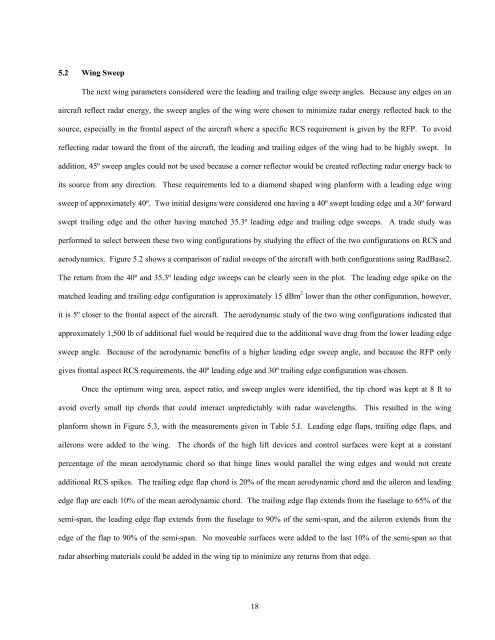
5.2 Wing SweepThe next wing parameters considered were the leading and trailing edge sweep angles. Because any edges on anaircraft reflect radar energy, the sweep angles of the wing were chosen to minimize radar energy reflected back to thesource, especially in the frontal aspect of the aircraft where a specific RCS requirement is given by the RFP. To avoidreflecting radar toward the front of the aircraft, the leading and trailing edges of the wing had to be highly swept. Inaddition, 45º sweep angles could not be used because a corner reflector would be created reflecting radar energy back toits source from any direction. These requirements led to a diamond shaped wing planform with a leading edge wingsweep of approximately 40º. Two initial designs were considered one having a 40º swept leading edge and a 30º forwardswept trailing edge and the other having matched 35.3º leading edge and trailing edge sweeps. A trade study wasperformed to select between these two wing configurations by studying the effect of the two configurations on RCS andaerodynamics. Figure 5.2 shows a comparison of radial sweeps of the aircraft with both configurations using RadBase2.The return from the 40º and 35.3º leading edge sweeps can be clearly seen in the plot. The leading edge spike on thematched leading and trailing edge configuration is approximately 15 dBm 2 lower than the other configuration, however,it is 5º closer to the frontal aspect of the aircraft. The aerodynamic study of the two wing configurations indicated thatapproximately 1,500 lb of additional fuel would be required due to the additional wave drag from the lower leading edgesweep angle. Because of the aerodynamic benefits of a higher leading edge sweep angle, and because the RFP onlygives frontal aspect RCS requirements, the 40º leading edge and 30º trailing edge configuration was chosen.Once the optimum wing area, aspect ratio, and sweep angles were identified, the tip chord was kept at 8 ft toavoid overly small tip chords that could interact unpredictably with radar wavelengths. This resulted in the wingplanform shown in Figure 5.3, with the measurements given in Table 5.I. Leading edge flaps, trailing edge flaps, andailerons were added to the wing. The chords of the high lift devices and control surfaces were kept at a constantpercentage of the mean aerodynamic chord so that hinge lines would parallel the wing edges and would not createadditional RCS spikes. The trailing edge flap chord is 20% of the mean aerodynamic chord and the aileron and leadingedge flap are each 10% of the mean aerodynamic chord. The trailing edge flap extends from the fuselage to 65% of thesemi-span, the leading edge flap extends from the fuselage to 90% of the semi-span, and the aileron extends from theedge of the flap to 90% of the semi-span. No moveable surfaces were added to the last 10% of the semi-span so thatradar absorbing materials could be added in the wing tip to minimize any returns from that edge.18


