Vendetta Final Proposal Part 1 (3.4 MB) - Cal Poly
Vendetta Final Proposal Part 1 (3.4 MB) - Cal Poly
Vendetta Final Proposal Part 1 (3.4 MB) - Cal Poly
- No tags were found...
You also want an ePaper? Increase the reach of your titles
YUMPU automatically turns print PDFs into web optimized ePapers that Google loves.
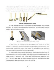
was determined that each wing would have to withstand 660,000 lb. Though each individual spar was not sized, it wasdetermined that if the main wing spars were 3 in thick (simple beam cross-section) the wing would be able to withstandthe 7-g maneuver.It is also important to note that the landing gear attach to a bulkhead just forward of the aft closure to the weaponsbay. This locates the airborne and ground laden load paths on top of each other, allowing for some redundancy in thestructure and resulting in a lighter aircraft. Another redundant feature is the aft wing main load path. This bulkhead actsas the main forward engine attachment point. Again, this allows for a minimum of large structural bulkheads and thuscreates a lighter aircraft. The wing attachment points are shown in Figure 7.2.The empennage structure follows the same methodology as the wing attachment structure. The vertical tailsattach to the aft primary carry through of the wing. The aft vertical attach point is the same as the primary load path forthe horizontal tails. The horizontal tail is an area of concern for the <strong>Vendetta</strong>. The horizontal surfaces are capable ofproducing tremendous forces on the aircraft. At full deflection, the horizontal stabilizers could produce a 10,000 poundforce which would be transmitted through the pivot. It was determined that a 4 inch diameter pivot would be capable oftaking the shear and bending stress produced by this force however the structural rigidity be compromised. The root ofthe horizontal was widened to allow for a 10 inch diameter pivot shaft and increased structural rigidity. The loads takenby the pivot must be transmitted to the keel of the aircraft. There is a ring carry through structure that distributes the loadfrom the pivot point to the central keel. Two secondary bulkheads back up this main bulkhead. The empennagestructure is shown in Figure 7.3.ForwardSecondaryBulkheadsMain GearAttachmentForwardPrimaryBulkheadAft SecondaryBulkheadsAft PrimaryBulkhead &Main EngineAttachmentFigure 7.2 - Wing Attachment Detail37


