

Vendetta Final Proposal Part 1 (3.4 MB) - Cal Poly
Vendetta Final Proposal Part 1 (3.4 MB) - Cal Poly
Vendetta Final Proposal Part 1 (3.4 MB) - Cal Poly
- No tags were found...

You also want an ePaper? Increase the reach of your titles
YUMPU automatically turns print PDFs into web optimized ePapers that Google loves.
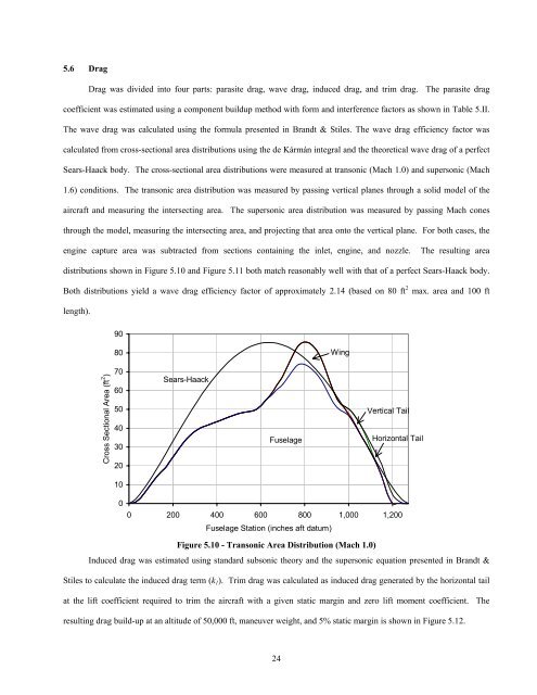
5.6 DragDrag was divided into four parts: parasite drag, wave drag, induced drag, and trim drag. The parasite dragcoefficient was estimated using a component buildup method with form and interference factors as shown in Table 5.II.The wave drag was calculated using the formula presented in Brandt & Stiles. The wave drag efficiency factor wascalculated from cross-sectional area distributions using the de Kármán integral and the theoretical wave drag of a perfectSears-Haack body. The cross-sectional area distributions were measured at transonic (Mach 1.0) and supersonic (Mach1.6) conditions. The transonic area distribution was measured by passing vertical planes through a solid model of theaircraft and measuring the intersecting area. The supersonic area distribution was measured by passing Mach conesthrough the model, measuring the intersecting area, and projecting that area onto the vertical plane. For both cases, theengine capture area was subtracted from sections containing the inlet, engine, and nozzle. The resulting areadistributions shown in Figure 5.10 and Figure 5.11 both match reasonably well with that of a perfect Sears-Haack body.Both distributions yield a wave drag efficiency factor of approximately 2.14 (based on 80 ft 2 max. area and 100 ftlength).9080WingCross Sectional Area (ft 2 )706050403020Sears-HaackFuselageVertical TailHorizontal Tail1000 200 400 600 800 1,000 1,200Fuselage Station (inches aft datum)Figure 5.10 - Transonic Area Distribution (Mach 1.0)Induced drag was estimated using standard subsonic theory and the supersonic equation presented in Brandt &Stiles to calculate the induced drag term (k 1 ). Trim drag was calculated as induced drag generated by the horizontal tailat the lift coefficient required to trim the aircraft with a given static margin and zero lift moment coefficient. Theresulting drag build-up at an altitude of 50,000 ft, maneuver weight, and 5% static margin is shown in Figure 5.12.24


