

Vendetta Final Proposal Part 1 (3.4 MB) - Cal Poly
Vendetta Final Proposal Part 1 (3.4 MB) - Cal Poly
Vendetta Final Proposal Part 1 (3.4 MB) - Cal Poly
- No tags were found...

You also want an ePaper? Increase the reach of your titles
YUMPU automatically turns print PDFs into web optimized ePapers that Google loves.
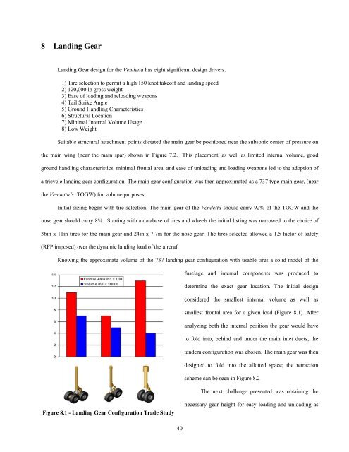
8 Landing GearLanding Gear design for the <strong>Vendetta</strong> has eight significant design drivers.1) Tire selection to permit a high 150 knot takeoff and landing speed2) 120,000 lb gross weight3) Ease of loading and reloading weapons4) Tail Strike Angle5) Ground Handling Characteristics6) Structural Location7) Minimal Internal Volume Usage8) Low WeightSuitable structural attachment points dictated the main gear be positioned near the subsonic center of pressure onthe main wing (near the main spar) shown in Figure 7.2. This placement, as well as limited internal volume, goodground handling characteristics, minimal frontal area, and ease of unloading and loading weapons led to the adoption ofa tricycle landing gear configuration. The main gear configuration was then approximated as a 737 type main gear, (nearthe <strong>Vendetta</strong>’s TOGW) for volume purposes.Initial sizing began with tire selection. The main gear of the <strong>Vendetta</strong> should carry 92% of the TOGW and thenose gear should carry 8%. Starting with a database of tires and wheels the initial listing was narrowed to the choice of36in x 11in tires for the main gear and 24in x 7.7in for the nose gear. The tires selected allowed a 1.5 factor of safety(RFP imposed) over the dynamic landing load of the aircraf.Knowing the approximate volume of the 737 landing gear configuration with usable tires a solid model of thefuselage and internal components was produced todetermine the exact gear location. The initial designconsidered the smallest internal volume as well assmallest frontal area for a given load (Figure 8.1). Afteranalyzing both the internal position the gear would haveto fold into, behind and under the main inlet ducts, thetandem configuration was chosen. The main gear was thendesigned to fold into the allotted space; the retractionscheme can be seen in Figure 8.2The next challenge presented was obtaining theFigure 8.1 - Landing Gear Configuration Trade Studynecessary gear height for easy loading and unloading as40


