

Vendetta Final Proposal Part 1 (3.4 MB) - Cal Poly
Vendetta Final Proposal Part 1 (3.4 MB) - Cal Poly
Vendetta Final Proposal Part 1 (3.4 MB) - Cal Poly
- No tags were found...

Create successful ePaper yourself
Turn your PDF publications into a flip-book with our unique Google optimized e-Paper software.
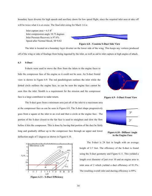
oundary layer diverter for high speeds and auxiliary doors for low speed flight, since the required inlet area at take offwill be twice what it is at cruise. The final inlet sizing for Mach 1.6 is:Inlet capture area = 6.5 ft 2Inlet compression angle 10.75 degreesInlet Pressure Recovery is 97.6%Speed after Normal Shock, M=0.82Figure 6.8 - <strong>Vendetta</strong> S-Duct Side ViewThe inlet is located on a boundary layer diverter on the lower side of the wing. This keeps any vortices producedoff of the wing or side of fuselage from being ingested by the inlet, as well as aid in inlet capture at high angles of attack.6.3 S-DuctS-ducts were used to move the flow from the inlets to the engine faces tohide the compressor face of the engine so it could not be seen. An S-duct frontalview is shown in Figure 6.9. The red parallelogram outlines the inlet while thedotted circle outlines the engine face, as can be seen the engine face cannot beseen thru the inlet. Stealth is a requirement for the mission and the compressorface is a large contributor to radar return.Figure 6.9 - S-Duct Front ViewThe S-duct goes from a minimum area just aft of the inlet to a maximum areaat the compressor face as can be seen in Figure 6.8. The S-duct shape progressivelygoes from a square at the inlet to an oval and then a circle at the engine face. Theportion of the S-duct closest to the fan face is used to straighten and slow the flowbefore it hits the compressor. This is done by having that portion of the duct be fairlylong and gradually diffuse up to the compressor face through an upper and lowerdeflection angle of 3 degrees as shown in Figure 6.10.Figure 6.10 - Diffuser Angleto the Engine FaceThe S-duct is 24 feet in length with an averageheight of 2.7 feet. The efficiency of the S-duct is foundusing the S-duct geometry and Figure 6.11. This yielded alength over diameter of just over 10 and an engine area toinlet area of 2 which yielded a duct efficiency of 91.5%.The resulting overall inlet and ducting efficiency is 89%.Figure 6.11 - S-Duct Efficiency34


