Vendetta Final Proposal Part 1 (3.4 MB) - Cal Poly
Vendetta Final Proposal Part 1 (3.4 MB) - Cal Poly
Vendetta Final Proposal Part 1 (3.4 MB) - Cal Poly
- No tags were found...
Create successful ePaper yourself
Turn your PDF publications into a flip-book with our unique Google optimized e-Paper software.
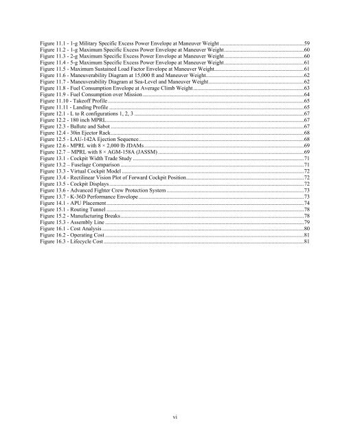
Figure 11.1 - 1-g Military Specific Excess Power Envelope at Maneuver Weight ............................................................59Figure 11.2 - 1-g Maximum Specific Excess Power Envelope at Maneuver Weight.........................................................60Figure 11.3 - 2-g Maximum Specific Excess Power Envelope at Maneuver Weight.........................................................60Figure 11.4 - 5-g Maximum Specific Excess Power Envelope at Maneuver Weight.........................................................61Figure 11.5 - Maximum Sustained Load Factor Envelope at Maneuver Weight................................................................61Figure 11.6 - Maneuverability Diagram at 15,000 ft and Maneuver Weight......................................................................62Figure 11.7 - Maneuverability Diagram at Sea-Level and Maneuver Weight....................................................................62Figure 11.8 - Fuel Consumption Envelope at Average Climb Weight ...............................................................................63Figure 11.9 - Fuel Consumption over Mission ...................................................................................................................64Figure 11.10 - Takeoff Profile............................................................................................................................................65Figure 11.11 - Landing Profile ...........................................................................................................................................65Figure 12.1 - L to R configurations 1, 2, 3 .........................................................................................................................67Figure 12.2 - 180 inch MPRL.............................................................................................................................................67Figure 12.3 - Ballute and Sabot ..........................................................................................................................................67Figure 12.4 - 30in Ejector Rack..........................................................................................................................................68Figure 12.5 - LAU-142A Ejection Sequence......................................................................................................................68Figure 12.6 - MPRL with 8 × 2,000 lb JDAMs..................................................................................................................69Figure 12.7 – MPRL with 8 × AGM-158A (JASSM) ........................................................................................................69Figure 13.1 - Cockpit Width Trade Study ..........................................................................................................................71Figure 13.2 – Fuselage Comparison ...................................................................................................................................71Figure 13.3 - Virtual Cockpit Model ..................................................................................................................................72Figure 1<strong>3.4</strong> - Rectilinear Vision Plot of Forward Cockpit Position....................................................................................72Figure 13.5 - Cockpit Displays...........................................................................................................................................72Figure 13.6 - Advanced Fighter Crew Protection System ..................................................................................................73Figure 13.7 - K-36D Performance Envelope ......................................................................................................................73Figure 14.1 - APU Placement.............................................................................................................................................74Figure 15.1 - Routing Tunnel .............................................................................................................................................78Figure 15.2 - Manufacturing Breaks...................................................................................................................................78Figure 15.3 - Assembly Line ..............................................................................................................................................79Figure 16.1 - Cost Analysis ................................................................................................................................................80Figure 16.2 - Operating Cost ..............................................................................................................................................81Figure 16.3 - Lifecycle Cost ...............................................................................................................................................81vi


