Tail Rotor Driveshaft Hanger
Tail Rotor Driveshaft Hanger
Tail Rotor Driveshaft Hanger
- No tags were found...

You also want an ePaper? Increase the reach of your titles
YUMPU automatically turns print PDFs into web optimized ePapers that Google loves.
BHT-212-CR&0CHAPTER 65 - TAIL ROTOR DRIVE SYSTEMCONTENTS - MAINTENANCE PROCEDURESParagraphNumberTitleChapter/SectionNumberPageNumber65-1 <strong>Tail</strong> rotor drive system ........................... 65-00-00 5000 00TAIL ROTOR DRIVESHAFT HANGER65-2666 000<strong>Tail</strong> rotor driveshaft hanger ...................... 65-00-00 765-3 Overhaul ....................................... 65-00-00 765-9A Replacement -- coupling temperatureindicator "TEMP-PLATES" ..................... 65-00-00 10A65-10 Painting -- tail rotor driveshaft hangerassemblies (212-040-600-001 and -009with magnesium hanger and 204-040-=3'00 00000617-005) ....................................... 65-00-00 11INTERMEDIATE (42°) GEARBOX65-11Intermediate (42°) gearbox ....................... 65-00-00 17000006660000000000000000000065-12 Deleted ........................................ 65-00-00 1765-21 Intermediate gearbox quills ....................... 65-00-00 2665-22 Input quill ...................................... 65-00-00 2665-29 Output quill .................................... 65-00-00 43CA)TAIL ROTOR (90°) GEARBOX65-36 <strong>Tail</strong> rotor gearbox ................................ 65-00-00 5565-37 Overhaul ....................................... 65-00-00 5565-46 Input quill ...................................... 65-00-00 710)0)000000000'0^FIGURESFigurePageNumber Title Number65-1 <strong>Tail</strong> rotor drive system components ................................... 665-2 <strong>Tail</strong> rotor driveshaft hanger ........................................... 1265-3 <strong>Tail</strong> rotor driveshaft coupling wear pattern ............................ 1465-4 <strong>Tail</strong> rotor driveshaft hanger wear limits ................................ 1565-5 <strong>Tail</strong> rotor driveshaft coupling "TEMP-PLATES" installation ............ 1665-6 Intermediate (42°) gearbox ............................................ 1965-7 Intermediate gearbox case damage limits ............................. 2165-8 Intermediate gearbox processing requirements ........................ 22A65-9 Intermediate gearbox pinion identification ............................. 2465-10 Intermediate gearbox input quill ....................................... 280)0)0)0)0)0)0)0)0)0)(>) (L)3:O-_'(>) (L)((DDRev. 465-00-00Page 1
BHT-212-CR&0FIGURES (Cont)FigureNumberZ11TitlePageNumber65-11 Intermediate gearbox input quill wear limits ........................... 3265-12 Gear and pinion wear patterns ........................................ 3465-13 Quill coupling teeth wear patterns ..................................... 3765-14 Quill roller bearing wear pattern ....................................... 3865-15 Quill sleeve damage limits ............................................ 3965-16 DELETED ............................................................. 4265-17 Intermediate gearbox output quill ..................................... 45033m0000-0-65-18 Intermediate gearbox coupling wear pattern .......................... 4765-19 Intermediate gearbox output wear limits ............................... 4965-20 DELETED ............................................................. 5465-21 <strong>Tail</strong> rotor gearbox ..................................................... 5765-22 <strong>Tail</strong> rotor gearbox wear limits ......................................... 6165-23 Gear and pinion wear pattern ......................................... 6265-24 <strong>Tail</strong> rotor gearbox corrosion damage limits ............................ 6465-25 Roller bearing inspection .............................................. 6665-26 <strong>Tail</strong> rotor gearbox output shaft damage limits ......................... 6765-27 <strong>Tail</strong> rotor gearbox shims and studs dimensions ....................... 6865-28 <strong>Tail</strong> rotor gearbox input quill .......................................... 7365-29 <strong>Tail</strong> rotor gearbox input quill wear limits .............................. 7565-30 Input quill coupling teeth wear pattern ................................ 76C')TABLESTableNumberTitlePageNumber65-1 Magnetic particle inspection ........................................... 8065-00-00Page 2 Rev. 4
BHT-212-CR&0CONSUMABLE MATERIAL LISTThe following consumable materials are required to perform the maintenance procedures withinthis chapter.ITEMNO.NOMENCLATURECAGE/FSCM/SOURCEC-001 Grease, Aircraft General Purpose, MIL-G-81322 (AeroshellNo.22 or Mobil No.28)0 000 00mN(DEE-c.00m0ECommercialC-005 Lubricant, Solid Film, MIL-L-46010 Commercial00)0EE ECCOC-010 Lubricating Oil, Turbine Engine, MIL-L-7808 CommercialC-011 Lubricating Oil, Turbine Engine, MIL-L-23699 CommercialC-015 Lubricant (Tube Pack) 204-040-755-5 97499C-100 Chemical Film Material (Alodine 1200 or 1201) MIL-C-81706,Class 1A, Form 11 (Dip Tank) or III (Brush-on). Apply perMIL-C-5541.C-103 Chromic Acid (Brush-On Solution) Chromic Acid and CalciumSulfateCommercialCommercialC-105 Corrosion Preventive; Fingerprint Remover, MIL-C-15074 98308C-108 LHE Cadmium Plating Solution (For Brush Cadmium Plating) 13929C-112 Cadmium Chromate Conversion Coating Micro Bronze No. 1or 76071Enthox 280 or 02258Alumigold orNo. 6 CD orDalic 5005C-114 Corrosion Treatment (A mixture of items C-113, C-212 andwater or items C-115, C-212 and water)C-116 Chromic Acid (Technical), O-C-303-1 CommercialC-201 Zinc Chromate Primer, TT-P-1757 CommercialC-202 Epoxy (Super-Koropon) Primer 22873C-203 Acrylic Lacquer, MIL-L-81352. Refer to text for color. CommercialC-204 Epoxy Polyamide Primer, MIL-P-23377, MIL-P-85582, Type I.Refer to text for color.C-210 Epoxy Paint, White Catalyzed Color No. 17875 per FED-STD-595CommercialCommercialC-211 Shellac, TT-S-300, Type 1, Grade B, Body 2 CommercialC-298 Adhesive, Epoxy, Devcon 2-Ton CommercialC-304 Solvent, Drycleaning, P-D-680, Type 11, pH Insignificant CommercialC-305 Aliphatic Naphtha, TT-N-95, Type II Commercial65-00-00Rev. 4 Page 3
F5.BHT-212-CR&0CONSUMABLE MATERIAL LIST (Cont)ITEMNO.NOMENCLATURECAGE/FSCM/SOURCEC-308 Adhesive, Sealant, 299-947-107, Type III, Class 7, MIL-S- 974998802, Class B2 or 83527Proseal 890 835740(d2 T-5(n-C-309 Methyl -Ethyl-Ketone (MEK), TT-M-261 B, pH Insignificant Commercial(Alternate where MEK use prohibited: RHO SOLV 756) 83527CDVia)CCDC-317 Adhesive, Magnabond 6398 (299-947-100, Type II, Class 2) 22121 or97499C-318 Cleaning Compound, Alkaline Base, MIL-C-87936, pH Value12 Max. (Detergent) CommercialC-334 1.1.1-Trichloroethane, MIL-T-81533 (Vapor) or O-T-620(Cold)0)0000-INr0)CommercialC-405 Lockwire, MS20995C32 (0.032 Inch Dia.) CommercialC-407 Abrasive Pad, Nylon Web (Scotchbrite) L-P-0050, Type I, 27713 orClass 1, Size 1 76381C-409 Use C-500C-423 Abrasive Cloth (P-C-458) or Paper (P-P-101) (All Grits) CommercialC-427 Barrier Material, Greaseproofed and Waterproofed, Flexible,MIL-B-121CommercialC-432 Nitric Acid, O-N-350 CommercialC-434 Plating Tape, No. 420 26066C-436 Paint Remover, Alkaline Type, General, MIL-R-81294 or 80244MIL-R-8633A or 81349Turco No. 5469 61102C-464 India Stone, SS-S-736 CommercialC-490 Cork Stopper, LL-S-731, Type I, Grade A, Class 2 (Sizespecified in text)CommercialC-500 Crocus Cloth, Abrasive Coated, A-A-1206 CommercialCD CD CD65-00-00Page 4Rev.4
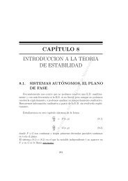
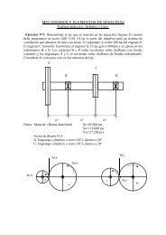
BHT-212-CR&OTAIL ROTOR DRIVE SYSTEM65-1. TAIL ROTOR DRIVE SYSTEM. (1), intermediate (42°) gearbox (2), and tailrotor (90°) gearbox (3).Principle components of the tail rotor drivesystem (figure 65-1) is the tail rotor driveshaft65-00-00Page 5
BHT-212-CR&O1. <strong>Tail</strong> rotor driveshaft2. Intermediate gearbox3. <strong>Tail</strong> rotor gearbox212-R-65-1Figure 65-1.<strong>Tail</strong> rotor drive system components65-00-00Page 6
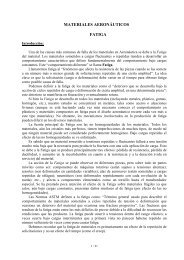
BHT-212-CR&OTAIL ROTOR DRIVESHAFT HANGER65-2. TAIL ROTOR DRIVESHAFTHANGER.65-3. OVERHAUL.m65-4. Disassembly.NOTEIf hanger is being disassembled forreplacement of part(s), instead ofoverhaul, disassemble only to extentnecessary.1. Remove retainer ring (1, figure 65-2),plate (2), and spring (3) from outer coupling(8).2. Remove nut (16), washers (5), bolt (4),and retainer plate (6).65-5. Cleaning.NUMBERC-304C-436MATERIALS REQUIREDcowNOMENCLATURESolvent0Paint Remover1. Wash all parts, except bearings, withsolvent (C-304). Dry with filtered, compressedair.2. Clean bearing by wiping with dry, lint-freecloth. Do not allow bearings to spin whiledrying.3. Remove paint from hanger with paintremover (C-436). Rinse with clean water.N(a(CDNOTEFor ease of maintenance, blockouter coupling to remain in outboard(extended) position. This willstabilize outer coupling duringdisassembly and assembly.3. Slide rear coupling (15) from splined shaft(11). Remove inner and outer couplings (7and 8) from forward end of splined shaft.Remove seal (10) from outer coupling (8).3A. Observe condition of grease. If greaseis very viscous (thick) and has a strongpungent odor, replace outer coupling (8) andinner coupling (7).°`2°4. Support inner race of bearing (13) andpress out shaft (11).5. Remove retainer ring (12) and pressbearing from hanger (14).6. Discard bearing at overhaul.((DD3-O65-6. Conditional Inspection.000(Do0-oNOTEIf records or physical appearance ofhanger indicates component wassubjected to an accident or incidentoutside realm of normal usage,perform Conditional Inspection asfollows. If no evidence is found,accomplish Normal Inspection,paragraph 65-7.-`a?-`(n30:c1. Visually inspect curvic faces of outer andrear couplings (8 and 15, figure 65-2) fordistortion or evidence of overheating.lfoverheat conditions are noted, refer toparagraph 65-7.2. Visually inspect mounting ears of hanger(14) for cracks or distortion.3. Visually inspect teeth of spherical faces ofinner and outer couplings (7 and 8) for cracksor galling.(n04. Check bearing (13) for freedom andsmoothness of rotation.65-00-00Rev.3 Page 7I
BHT-212-CR&O5. Inspect detail parts for cracks bymagnetic particle or fluorescent penetrantmethods as applicable (paragraph 65-7)U)+-.0(BHT-ALL-SPM).(finNOTE,-.0If inspection reveals cracks ordistortion indicative of excessiveloads in any one detail part, entireassembly shall be consideredunserviceable and nonreparable.(OD06. Accomplish Normal Inspection (paragraph65-7).65-7. Normal Inspection.1. Visually inspect all parts for damage orexcessive wear.NOTEWear limits are provided to showrequired fit between mating parts. Itis not intended all dimensions bechecked as a prescribed overhaulprocedure. However, parts exhibitingevidence of wear or physicaldamage shall be checkeddimensionally.NOTEOvertemperature indicator dots ontemperature indicator TEMP-PLATES are of a white or light graycolor and turn black when exposedto an overtemperature condition.Chemical contamination can alsocause the indicating dots to turnblack.0(02.Q-2. Inspect inner coupling (7, figure 65-2) for 5. Inspect outer coupling (8, figure 62-5)acceptable wear patterns (figure 65-3). temp erature ind icator TEMP-PLATES (9) forevid ence of overtemperature indication. If3. Inspect following parts by magnetic overtemperatureindication is noted, performparticle (Code M) or fluorescent penetrant cou pling over temperature inspection as(Code F) (BHT-ALL-SPM), as applicable. follo ws:Demagnetize parts after magnetic inspection.a. Inspect outer coupling cadmium platingfor being discolored (circumferential tan orFigure, NomenclatureCodelight brown band) or blistered. If cadmiumIndex No.plate discoloration or blistering is found,replace outer coupling and inner coupling.(now0000000^a='¢;,65-2, 4 Bolt M65-2, 6 Retainer plate F65-2, 7 Inner coupling M65-2, 8 Outer coupling M65-2, 11 Shaft M65-2, 14 <strong>Hanger</strong> (see note) F/M65-2, 15 Rear coupling MNOTEPerform fluorescent penetrantinspection on magnesium hangers(14) and magnetic particle inspectionon steel hangers (14).4. Inspect parts dimensionally and replaceparts which exceed inspection limits (figure65-4).E.L-,(OD.(!)3.7a000-000b. Inspect gear teeth of outer couplingand inner coupling for being discolored(brown or blue) in the normally bright contactpatterns. If discoloration is found, replaceouter coupling and inner coupling.c. Inspect outer coupling and innercoupling under 5x to 10x magnification forteeth exhibiting signs. of metal smearing ortearing in the contact patterns. If smearing ortearing is found replace outer coupling andinner coupling.d. Inspect grease from couplings for beingvery viscous (thick) and having a strongpungent odor. If grease is found to be viscous(thick) and having a strong pungent odor,replace outer coupling and inner coupling.65-00-00Page 8 Rev. 3
BHT-212-CR&O,..:+3NOTEIf TEMP-PLATES are to be replaced,replace TEMP-PLATES aftercompleting entire inspection andrepair procedures and couplingshave been determined serviceableand prior to assembly.5A. Inspect outer coupling (8) temperatureindicator TEMP-PLATES (9) for deterioration,debonding or discoloration of epoxy coatingthat prevents interpretation of indicating dots.If deterioration, debonding, or discoloration ofepoxy is found, replace TEMP-PLATES inaccordance with paragraph 65-9A.-DI6. Inspect bearing (13) for evidence ofoverheating such as discoloration of bearing(blue to blue/black in color), multicolorappearance of hanger (14) which darkensadjacent to bearing. Any of the aboveconditions are cause to discard bearing.Brown color of bearing shield is normal and isnot evidence of overheating.con-00(D7. Hold bearing (13) outer race and turninner race by hand and simultaneously loadbearing by pressing axially on inner race.Obvious roughness, catching, or binding arecause to discard bearing.8. Deleted.9. Inspect hanger (14) for mechanical andcorrosion damage as follows:a. <strong>Hanger</strong> (14) is unserviceable andnonreparable if evidence of overheating isco.present.b. Inspect hanger for corrosion damage.Superficial corrosion damage is acceptable ifcorrosion is removed and hanger cadmiumplate is touched up.c. Inspect lubrication in bearing andhanger.((DDRev.365-00-00Page 8A/8B
BHT-212-CR&O10. Inspect inner coupling (7) for wear inarea contacted by seal (10). Rough surfaceand/or wear that would cause lubricantleakage is not acceptable.11. Inspect spring (3), bolt (4), retainer platet7)(CDM..(6), retainer rings (1 and 12), plate (2), andnut (16) for mechanical and corrosiondamage. Any damage which will affectfunction is not acceptable.65-8. Repair.NUMBERMATERIALS REQUIREDNOMENCLATUREC-108 Brush CadmiumPlating SolutionC-464 India StoneC-500 Crocus Cloth1. Replace all unserviceable parts and sealson assembly.2. Replace coupling seal (10, figure 65-2)and bearing (13) upon assembly.3. Dress splines of inner and outer couplings(7 and 8) with India stone (C-464), asnecessary, to blend out burrs, small nicks, orscratches.4. Polish nicks, burrs, or scratches onexterior surfaces with crocus cloth (C-500).5. Treat repaired cadmium plated surfaceswith brush cadmium plating solution (C-108)(BHT-ALL-SPM).65-9. Assembly.NUMBERcC-001C-015--IMATERIALS REQUIREDNN^1111-1NOMENCLATUREGrease...................? CAUTION ?Lubricant (Tube Pack)IF COUPLING SHAFT (11, FIGURE65-2), FORWARD INNERCOUPLING (7), OR REARCOUPLING (15) IS TO BEV-'mREPLACED, ENSURE MESHINGSPLINES HAVE 26 SPLINES ANDNOT 24 SPLINES.THE 212-040-602-1 AND -5S H A F T S A R E N O TINTERCHANGEABLE WITH 212-040-602-3 AND -7 SHAFTS. THE212-040-602-3 AND -7 SHAFTSARE LONGER AND HAVE ASMALLER OUTSIDE DIAMETER TOACCOMMODATE 204-040-623-3BEARING.1. Support inner race of bearing (13) andpress shaft (11) into bearing.NOTEBearing journal of shaft (11) must becentered on inner race of bearing(13) within 0.003 to 0.016 in. (0.0762to 0.4064 mm).2. Support hanger (14) and press bearingand shaft into hanger. Secure bearing withretainer ring (12).6. Replace parts which exceed allowablewear limits.7. Replace temperature indicator TEMP-PLATES if necessary. Refer to paragraph 65-9A.65-00-00Rev. 3 Page 9
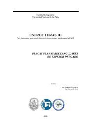
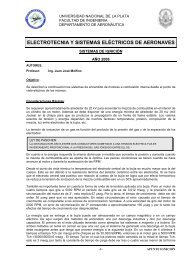
BHT-212-CR&0(b-n--1 0-ca0)0ohm^mNOTEA workaid may be fabricated (figure65-2, detail B) to aid installation ofseal (10, figure 65-2).3. Install seal (10) into outer coupling (8)seal groove as follows:ate-O`4-poiU-0+0.,E0 0a. Apply a light coat of lubricant (tubepack) (C-015) to outer circumference of seal(10).b. Install seal (10) into outer coupling (8)seal groove with lip of seal toward internalsplines to outer coupling (8), as shown infigure 65-2, detail A.NOTESeal (10) will be partially seated andinner coupling (7) will be used as abackup, in reverse (see detail A) tofully seat outer circumference edgeof seal into outer coupling sealgroove.C. Using inner coupling (7) as a backupand placed (detail A), firmly press down (handQ-0pressure only) on outer coupling (8),simultaneously tuck outer circumference edgeof seal (10) with workaid into outer coupling(8) seal groove.d. Continue pressing around seal (10)with workaid until seal (10) is fully seated.Remove inner coupling (7) from outercoupling (8).4. Hand pack internal splines of outercoupling (8) with lubricant (tube pack) (C-015)...to 0.12 in. (3.048mm) deep over top ofinternal splines for full length of exposedsplines. A workaid may be fabricated (figure65-2, detail C) to obtain depth of grease.((DD=..0(ODU.)NOTEEnsure inner coupling (7) is correctfor tail rotor driveshaft hangercoupling, overall length is 2.07 to2.08 in. (52.578 to 52.832 mm).0-.,.-r4-0O+,0Coupling for 42° and 90° gearbox is1.87 to 1.88 in. (47.498 to 47.752mm) long.5. Install inner coupling (7), with small endthrough seal (10). Bottom out inner couplingagainst seal.6. Assemble retainer plate (6) and rearcoupling (15) onto splined end of inner shaft(11). Install inner and outer coupling (7 and8), retainer plate (6) on opposite end of innershaft (11). Install bolt (4) through retainerplate (6) with bolt head toward coupling end,with washers (5) and nut (16). Torque nut 50to 70 in.lbs. (5.649 to 7.9086 Nm) and securewith cotter pin.7. Place spring (3) onto alignment probe on Irear side of cover plate (2). Position springand cover on outer coupling (8), compressspring and install retainer ring (1). Ensureretainer ring is fully seated.NOTERefer to paragraph 65-10 forpainting of 212-040-600-001 and -009 tail rotor driveshaft hangerassemblies.°-.0)(D65-00-00Page 10Rev.4
BHT-212-CR&0NOTEIf hanger bearing (13) has beenreplaced during overhaul of hangerassembly and is new, do notlubricate bearing with a hand greasegun. The bearing has beenlubricated at the factory andadditional lubricant may damagebearing seal.8. Lubricate hanger bearing (13) with handgrease gun, using grease (C-001), Mobil 28only.1 9. The tail rotor hanger will be tagged withdate of lubrication and an entry made incomponent historical record, if hanger is to bereturned to stock.1 10. When tail rotor hanger is installed onhelicopter, an entry will be made in helicopterlog and flex couplings lubrication log.65-9A. REPLACEMENT - COUPLINGTEMPERATURE INDICATOR TEMP-PLATES.Dl.MATERIALS REQUIREDRefer to BHT-ALL-SPM for specification andsource.NUMBERNOMENCLATUREC-298 Epoxy AdhesiveC-309 Methyl -Ethyl- Ketone(MEK)C-318C-436Cleaning CompoundPaint Remover1. Remove epoxy coating and TEMP-PLATES using paint remover (C-436). Repeatprocess until no trace of epoxy is present..................CAUTION..................-pC+.N-0CONTAMINATION. ANYQ..0-0E0)°06-0CC)c2)--ICONTAMINATION COULD ALLOWTHE TEMP-PLATES TO COME OFFOR I N D I C A T E F A L S ETEMPERATURES.(Q0)LLs-.n30Q2)DAD2. Prepare outer coupling surface forbonding by scrubbing surface clean with acloth moistened with an authorized cleaner,such as MEK (C-309) to remove allcontamination. Before the cleaner solventdries, wipe the surface dry with a clean cloth.The cleaned surface should be at least 0.50m`"0X00inch (12.70 mm) larger than the TEMP-PLATES. Refer to figure 65-5 for location ofTEMP-PLATES on outer coupling.3. Accomplish a water break-free test onthe prepared bonding surface by applyingdistilled or demineralized water from asuitable, dispenser (such as a squeeze bottle).The water must flow into a continuous filmwithout gathering into distinct water dropletswithin 25 seconds after application on thesurface. Wipe dry with a clean cloth. Ensurethe bonding surfaces are not subsequentlycontaminated.4. If the coupling bonding surface will notmeet the water break-free test requirementsand the cleaning materials are notcontaminated, clean coupling bondingsurfaces as follows.NOTEFollow the manufacturersrecommendations for proper watermixtures.a. Using an authorized alkaline cleaningcompound (C-318) and cloth, scrub thecoupling bonding surface clear. Followcleaning with a thorough water rinse.b. Thoroughly dry coupling surfaces.C. Repeat water break-free test as statedabove.BONDING SURFACE AND TEMP-PLATES MUST BE FREE OF ALL65-00-00Rev.4 Page 1 0A
BHT-212-CR&O--{-gym2 CAUTIONIN ORDER TO PREVENTCONTAMINATION OF THE TEMP-PLATES ADHESIVE BACKING,ENSURE THAT WORK AREA ANDHANDS ARE THOROUGHLYCLEANED BEFORE WORKINGWITH TEMP-PLATES.DO NOT PRESS OR RUB THETEMP-PLATES WITH BAREFINGERS DURING INSTALLATIONON THE COUPLING AS THIS WILLCONTAMINATE THE SURFACES.APPLY EPOXY COATING TO THETEMP-PLATES IMMEDIATELYFOLLOWING INSTALLATION OFTHE TEMP-PLATES ONCOUPLING.m0m5. Carefully prebend the temperatureindicator TEMP-PLATES to match the Vcontour of coupling surface. Do not creasethe TEMP-PLATES sharply.NOTEWorking one TEMP-PLATE at atime, repeat steps 6 and 7 until allTEMP-PLATES are installed oncoupling.6. Remove protective backing from theTEMP-PLATE and carefully position onto thesurface prepared in step 2.7. Using a clean cloth or cotton swab, workthe TEMP-PLATE into the contour of thecoupling. A thoroughly cleaned firm rubber(edge of a block type eraser) workaid may beutilized to work TEMP-PLATE into full contactwith the coupling surface. Ensure the TEMP-PLATE is in full contact with the couplingsurface. Do not press or rub the TEMP-PLATE with bare fingers.m(t3-i.-0,NOTEUse of any epoxy adhesive otherthan Devcon 2-Ton is notauthorized.8. Prepare Devcon 2-Ton epoxy adhesiveepoxy adhesive (C-298) as follows:a. Pour equal amounts of epoxy Part Aand Part B into a solvent proof container.b. Vigorously mix Part A and Part B with abrush such as an artist brush.c. A few drops of authorized thinner, suchas MEK (C-309), may be added to the epoxyduring the mixing operation to reduce theviscosity to a level that permits uniform brushapplication of the epoxy mixture. Do not thinthis mixture such that it runs when applied toa vertical surface. The final viscosity of theepoxy should be similar to a heavily bodiedpaint. Too thin a mixture may seep into thetemperature indicator TEMP-PLATE andcause the indicator dots to turn black in whichevent, the TEMP-PLATE must be removedand replaced. Working time for the mixture isapproximately 15 minutes.D-109. Using a soft-bristled brush, uniformlyapply the epoxy coating over the TEMP-PLATES to a thickness of approximately0.002 to 0.004 inch (0.0508 to 0.1016 mm)similar to a coat of paint. The coating shouldbe uniform in appearance, totally cover thesurface of the TEMP-PLATES and extendapproximmately 0.25 inch (6.35 mm) beyondthe edges of the TEMP-PLATES.CAUTION 2DO NOT EXPOSE THE EPOXYCOATING TO OIL, GREASE,CLEANING SOLVENT OR OTHERCHEMICALS DURING CURE.c065-00-00Page 10BRev.3
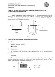
BHT-212-CR&O10. Allow epoxy coating to cure at roomtemperature approximately 60 to 100°F (15.6to 38°C) for a minimum of six hours prior tohelicopter operation. For best results, allowepoxy to cure overnight prior to operatinghelicopter or exposure to oil or grease.0((DDtea)-,+o =":-CDNOTE0.." 0000An alternate source of heat can beused if the temperature does notexceed 180°F (82°C).(ate11. After one hour epoxy curing time atroom temperature, the epoxy coating totalcuring time can be accelerated by placing thecoupling in a temperature controlled oven forone to two hours at a temperature of 150 to180°F (66 to 82°C).12. Following the cure, the TEMP-PLATESshould conform to the contour of the couplingand be free of lifted edges. Indicating dots onTEMP-PLATES must remain the original whiteor light gray with no full or partial blackdiscoloration.13. Accomplish an adhesion test on eachTEMP-PLATE installation. Press a 1.00 inch(25.4 mm) wide strip of high adhesion tapeonto the TEMP-PLATE and epoxy overcoat.The tape should extend beyond the edge ofthe epoxy overcoat. Grasp one end of thetape at approximately 90 degrees from thesurface and remove tape in one abruptmotion. Lifting or peeling of the epoxy coatingor TEMP-PLATE is not acceptable. If lifting orpeeling is detected, remove and replaceTEMP-PLATE by repeating procedure..+J'07mo014. Repeat procedure for all tail rotor driveouter couplings.Q.-°O-(DD065-10. PAINTING - TAIL ROTORDRIVESHAFT HANGER ASSEMBLIES (212-040-600-001 AND -009 WITH MAGNESIUMHANGER AND 204-040-617-005).MATERIALS REQUIRED:_/p°)NUMBERC-204C-305m0-0MATERIALS REQUIRED (CONT)D^100+=O-0NOMENCLATUREPrimerAliphatic Naphtha1. Touch up exposed magnesium surfaceson hanger (14, figure 65-2) with chromic acid(C-103) (BHT-ALL-SPM).E oE2. Mask off bearing, seal, and couplings.Clean hanger in area to be painted with cleancheesecloth wetted with aliphatic naphtha (C-305). Wipe dry with clean cheesecloth beforenaphtha evaporates.3. Apply two spray coats of primer (C-204)0.4 to 0.9 mils (10.9 to 22.9 um) thickness.NOTEApply aluminized lacquer spray coatnot less than thirty minutes and notmore than eight hours, after epoxyprimer is applied.(ac4. Spray on first coat of aluminized, colorNo. 17178 lacquer (C-203) 0.4 to 0.6 milthickness. Allow to dry for thirty minutes toone hour and apply second coat.NOTEIf second coat of lacquer cannot beapplied within time limits noted in0(0 '-'step 5., second coat may be delayedfor up to seventy-two hours, butsurface to be painted shall becleaned with a tack rag prior toapplying second coat.5. Allow last coat of aluminized lacquer todry for forty-eight hours and remove maskingtape.6. Deleted.NUMBERC-103C-203NOMENCLATUREChromic AcidLacquer65-00-00Rev.3 Page 11
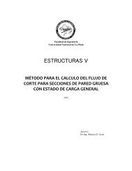
mI-:BHT-212-CR&O15INTERNAL SPLINESINNERCOUPLING(7)USEDASBACK-UPTOPUSHLIPOFSEAL00)UPSEAL(10)FULLYSEATEDOUTERCOUPLING(8)INSTALLEDINVERTEDONINNERCOUPLING16212-R-65-2-1Figure65-2.<strong>Tail</strong>rotordriveshafthanger(Sheet1of2)GREASEGROOVESIN204-040-623-003BEARING1.Retainerring9.Deleted2.Plate10.Seal3.Spring11.Shaft4.Bolt12.Retainerring5.Washer13.Bearing6.Retainerplate14.<strong>Hanger</strong>7.Innercoupling15.Rearcoupling8.Outercoupling16.NutNOTELocationofTemperatureindicatorTEMP-PLATE.65-00-00 Page12Rev.3
L}1.0 IN. 125.4 mm) RADIUS8 IN. (203.20 mm)--- 7.0 IN. 1177.80 mm)-2.0 IN.(50.8 mm)0.125 IN.(3.18 mm) 0.25 IN.L1.0 IN. (25.4 mm) (6.35 mm)BHT-212-CR&ONOTEQ2Make from plexiglass or similar material, remove all sharp edges.DETAIL B1.051N.(26.67 mm)0.27 IN. (6.80 mm)0.25 IN. (6.35 mm)771HANDLE LENGTH IS OPTIONAL0.1 IN.(2.54 mm)RADIUSU0.1201N.(3.05 mm)1_-I0.357 IN.f (9.53 mm)1.25 IN.(31.75 mm)COUPLINGTAIL ROTORDRIVESHAFT0.312 IN.(7.92 mm)Q3Make locally from 1 /4 in. (6.35 mm) plastic, or similar material.DETAIL C212-R-65-2-2Figure 65-2. <strong>Tail</strong> rotor driveshaft hanger (Sheet 2)65-00-00Page 13
BHT-212-CR&OA Acceptable pattern typical of low operatingtime.B Acceptable pattern typical of couplings whichhave operated with normal misalignment for alonger period of time than that shown in A.W//\\4C Acceptable pattern denoting operation athigher torque than that shown in A and B.+O+ +O+D Acceptable pattern showing a pitted tooth.This condition is acceptable on all teeth.=mmEPattern shows a more severe condition oftooth pitting than that shown in D. There isno metal projecting above the normal face ofthe tooth, indicating that the pitted area ispolishing over. This condition may exist on allteeth. Couplings with pits larger than 1/32Inch (0.79375 mm) diameter should be replaced.00000oooo65 3Figure 65-3.<strong>Tail</strong> rotor driveshaft coupling wear pattern65-00-00Page 14
BHT-212-CR&O7WMt mf ills a iI m,W0MIN.MAXITEM NOMENCLATURE INCHES mm INCHES mm(,)1 Outer Coupling - Internal Spline(Use 0.1309 IN. (3.32486 mm)Between pins 1.8290 46.4566 1.8360A 46.6344diameter pins)3DC 3C'-'C M'8CV)aC. pC.a)-2 Inner Coupling - External Spline(Use 0.1080 IN. (2.7432 mm)Over pins 2.1590 54.8386 2.1740 55.2196diameter pins)3 Inner Coupling and RearCoupling - Internal Splines(Use 0.0960 IN. (2.4384 mm)diameter pins)Between pins 1.1465 29.1211 1.1578 29.408124 Shaft - External Spline(Use 0.0960 IN. (2.4384 mm)Over pins 1.4424 36.63696 1.4465 36.7411diameter pins)5 Shaft - Bearing Seat(212-040-602-1 and 5) 1.3776 34.99104 1.3784 35.01136(212-040-602-3 and 7) 1.3476 34.22904 1.3484 34.249366 Bearing - Inner Diameter(204-040-623-1 and 5) 1.3775 34.9885 1.3781 35.00374(204-040-623-3) (Regreasable) 1.3477 34.23158 1.3481 34.2417400)LO..PLL)X007 Bearing - Outer Diameter 2.4403 61.98362 2.4409 61.998868 <strong>Hanger</strong> - Inner Diameter 2.4401 61.97854 2.4409 61.99886NOTEA Maximum depth of wear 0.005 inch (0.127 mm) measured from unworn face of tooth.Figure 65-4.<strong>Tail</strong> rotor driveshaft hanger wear limits212-R-65-465-00-00Page 15
BHT-212-CR&ON7 U----HANGER-204-040-604-005 COUPLINGREFr-i P-16000-1 TEMP-PLATE (RED BORDER)2 REQD-180 DEGREES APARTEQUALLY SPACED WITHIN 0.3 IN. (7.62 mm)IDENTIFICATIONPLATE0.74± 0.030 IN.(18.79±0.762 mm)212-R-65-5Figure 65-5.<strong>Tail</strong> rotor driveshaft coupling TEMP-PLATES installation65-00-00Page 16Rev.3
B HT-212-CR&0INTERMEDIATE (42°) GEARBOX65-11. INTERMEDIATE (42°) GEARBOX.65-12. DELETED65-13. Disassembly.NUMBERT1013080T101350SPECIAL TOOLS REQUIREDNOMENCLATUREJackscrewBacklash clampT102030-3 Backlash clamp204- 040- 001 -17 Puller tool (Sightglass)PAT-5Sor Equivalent2. Release pin (24) which secures chain tocase and remove cap (26). Remove packing(25) from cap. Discard packing.r:-.,-a)^N-03. Remove retainer ring (19), glass (21),and indicator (22). Use suitable tool toremove glass. Carefully remove packing (20)from glass. Discard packing.
BHT-212-CR&0I65-14. Cleaningmm300MATERIALS REQUIREDRefer to BHT-ALL-SPM for specification andsource.NUMBERC-010 Lubricating OilC-011 Lubricating OilNOMENCLATUREC-105 Corrosion PreventiveC-304 SolventC-436 Paint RemoverC-486 Cheesecloth1. Clean all parts with solvent (C-304).2. Dry parts with low pressure, filtered air orcheesecloth (C-486) Do not allow drybearings to spin.3. Remove sealant from gearbox case (6,figure 65-6) with plastic scraper.NOTEParts requiring fluorescent penetrantinspection shall be stripped of allfinishes.4. Remove all paint and primer fromgearbox case using paint remover (C-436).(°)(CDO'605. When parts are not to be usedimmediately after cleaning, gently agitateparts in corrosion preventive (C-105) and airdry. Apply protective coat of approvedlubricating oil (C-010) or lubricating oil (C-011).65-15. Conditional InspectionIfNOTErecords and/or physicalappearance of gearbox indicateassembly has been subjected to anaccident or incident outside realm ofr-0normal usage, perform ConditionalInspection as follows. If gearboxdoes not require ConditionalInspection, accomplish NormalInspection (paragraph 65-16).1. Inspect gearbox and gearbox records todetermine whether gearbox has beensubjected to an accident or incident outsidethe realm of normal usage which would=30require conditional inspection. Refer to BHT-(DD:.,212-MM, for definition of accidents orincidents which require that conditionalinspection be conducted..-.(NDD))E-i.2. If conditional inspection is not required,proceed with normal inspection, paragraph65-16.0°:3o-c1-03. Check gearbox for free rotation andbacklash of gears. Backlash should not varymore than 0.002 inch (0.0508 mm), whenchecked at different points around gear.4. Perform fluorescent penetrant inspectionof gearbox case (16, figure 65-6) (BHT-ALL-SPM).NOTEIf inspection reveals cracks ordistortion, gearbox shall beconsidered unserviceable andnonrepairable.5. Accomplish Normal Inspection,paragraph 65-16.65-16. Normal Inspection1. Inspect gearbox case (6, figure 65-6) fordamage which would cause it to benonserviceable or nonreparable.2. Inspect studs and washer seats (9 and 8)for looseness, damage, and corrosion.3. Inspect gearbox case quill ports for4.4100 to 4.415 inches (112.014 to 112.141mm) inside diameter.4. Inspect oil filler cap (26, figure 65-6) andadapter (23) for damage and wear.65-00-00Page 18Rev.4a))
BHT-212-CR&05. Inspect oil level sight glass (21) forcracks, crazing, scratches, or discoloration.Inspect indicator (22) for stained or peeledpaint.6. Inspect chip detector (17) for obviousdamage.7. Inspect gearbox case for corrosion andfor elongated mounting bolt holes (figure 65-7).8. Perform fluorescent penetrant inspectionof gearbox case (BHT-ALL-SPM).9. Inspect shim plate (10, figure 65-6) fordamage and wear.(Do0.0--l-6NOTEIf inspection reveals cracks ordistortion, gearbox case shall beconsidered unserviceable andnonrepairable.10. Inspect chip detector (17) for obviousdamage.NOTEr«00Overtemperature indicator dots ontemperature indicator "TEMP-PLATES" are of a white or light graycolor and turn black when exposedto an overtemperature condition.Chemical contamination can alsocause the indicating dots to turnblack.Imo11. Inspect outer couplings (13 and 28)temperature indicator "TEMP-PLATES" orevidence of overtemperature indication. Ifovertemperature indication is noted, performcoupling overtemperature inspection asfollows:L(0(LOa. Inspect outer coupling cadmium platingfor being discolored (circumferential tan orlight brown band) or blistered. If cadmiumplate discoloration or blistering is found,replace outer coupling and inner coupling.-(p0_a-DO4-+O.-Q'-ac-00i'-'"'U,_3(Qb. Inspect gear teeth of outer couplingand inner coupling for being discolored(brown or blue) in the normally bright contactpatterns. If discoloration is found, replaceouter coupling and inner coupling.C. Inspect outer coupling and innercoupling under 5x to 10x magnification forteeth exhibiting signs of metal smearing ortearing in the contact patterns. If smearing ortearing is found, replace outer coupling andinner coupling.d. Inspect grease from couplings forbeing very viscous (thick) and having a strongpungent odor. If grease is found to be viscous(thick) and having a strong pungent odor,replace outer coupling and inner coupling.NOTEIf "TEMP-PLATES" are to bereplaced, replace "TEMP-PLATES"after completing entire inspectionand procedures and couplings havebeen determined serviceable andprior to assembly.12. Inspect outer couplings (13 and 28)temperature indicator "TEMP-PLATES" fordeterioration, debonding or discoloration ofepoxy coating that prevents interpretation ofindicating dots. If deterioration, debonding, ordiscoloration of epoxy is found, replace"TEMP-PLATES" in accordance withparagraph 65-9A.poi65-00-00Rev.4 Page 18A/1813
BHT-212-CR&O1. Output quill2. Nut3. Washer (2)4. Shim plate5. Screw6. Case7. Data plate8. Washer seat9. Stud10. Shim plate1 1 . Screw12. Packing13. Coupling14. Nut15. Washer (2)16. Input quill17. Chip detector18. Packing19. Ring20. Packing21. Glass22. Indicator23. Oil filler adapter24. Pin25. Packing26. Cap27. Chain28. Coupling006a0+ O=_,4;19151410NOTEQ Location of temperature indicator TEMP-PLATES.13212-R-65-6Figure 65-6.Intermediate (42°) gearbox65-00-00Rev.3 Page 19
BHT-212-CR&065-17. Repaircoo...La=`goo'-o3EECADE-0MATERIALS REQUIREDRefer to BHT-ALL-SPM for specification andsource.NUMBERC-100C-105C-108C-112C-116C-204C-308C-423C-432C-494CJ)cc-0U)ENOMENCLATUREChemical Film MaterialCorrosion PreventiveBrush CadmiumPlating SolutionCadmium ChromateConversion Coating00Chromic AcidPrimerAdhesiveAbrasive cloth orPaperNitric AcidInkNOTEReplace case if structural damage tostud threads or mounting bolt holesare elongated so repair limits areexceeded.1. Replace parts which exceed allowablewear limits.2. Repair corrosion damage on the case asfollows (figure 65-7):a. Flange repair: Machine off upper faceto a minimum flange thickness of 0.40 inch(10.16 mm) (dimension B, figure 65-7)provided this leaves no pits in excess of0.010 inch (0.254 mm) deep and affectedarea does not exceed inspection limits.Rework case using a 0.875 inch (22.225 mm)...momfro3.213.00diameter spotface with 0.062 inch (1.5748mm) corner radius. Machined surface finishshall be 63 RMS or better.65-00-00Page 20Rev.4b. Stud hole damage: Remove damagedor loose studs. Use suitable tool to grip studand turn out slowly and evenly to avoidseizure and breakage. If stud hole threads aredamaged, repair or replace case as required.a0-5 -"`con'-"cc.,-«4+,aS11C70If corrosion or other damage has notpenetrated past first thread,follows (BHT-ALL-SPM):D.c((DD33.rework case as(1) Machine or drill out damagedthread. Do not exceed depth of one thread.2.3Clean out diameter shall equal major threaddiameter.(2) Break all sharp edges, except inarea of threads. Clean out small vent hole inbottom of threaded hole. Treat bare surfaceswith chemical film material (C-100).(3) Replace stud (BHT-ALL-SPM).(4). Fill all counterdrilled holes withadhesive (C-308) flush with top of case.c. Repair minor scratches, nicks, and pitson noncritical surfaces with abrasive cloth orpaper (C-423).d. Cases with corrosion damage withinacceptable limits must be treated byimmersion in a hot chromic acid bathconsisting of 20 to 24 ounces (591.4 to709.68 ml) of chromic acid (C-116) per gallon(/j3-t3-firc>,=r,
BHT-212-CR&0Required dimensions shall be met afterplating (BHT-ALL-SPM).b. If original shim plate is missing ormixed with other shim plates, determinerequired dimensions of replacement shimplate as follows:(1) Examine case for referencedimension which is metal stamped or vibro-,-.etched on part adjacent to applicablemounting surface.(2) Subtract dimension etched orstamped on case from 3.4670 to 3.4675inches (88.0618 to 88.0745 mm) to giveTWOc°E`(flrequired shim thickness, after plating.Rev.465-00-00Page 20A/20B
BHT-212-CR&0SIDE VIEWVIEW LOOKING AFT0.290 IN.17.366 mm)MAXIMUM ACCEPTABLEELONGATION OFMOUNTING BOLT HOLESNOTES1. Corrosion pitting on upper machined face at four mounting bolt holes is acceptable provided it is nomore 0.020 inch (0.508 mm) deep, no more than 20 percent of total area is pitted, no more than 10percent of the area under washer is pitted and minimum thickness of flange in pitted area is no less than0.430 inch (10.992 mm).2. Cases having damage exceeding inspection limits may be reworked by machining off upper face to aminimum flange thickness of 0.400 inch (10.16 mm) (see dimension B above) provided this leaves nopits in excess of 0.010 inch (0.254 mm) deep and affected area does not exceed limits given above.CI)3. Rework case using a 0.875 inch (22.225 mm) diameter spot face with 0.062 inch (1.5748 mm) cornerradius. Machined surface finish must be 63 RMS or better.°)yCSI4. Corrosion pitting in area A is acceptable provided it is no more than 0.030 inch (0.762 mm) deep and nomore than forty percent of area within any one inch square (25.4 square mm) nor twenty percent oftotal area A at either bore is pitted. Structural damage to threaded holes for studs is acceptableprovided damage does not extend past first thread.a..coo=E°-'Figure 65-7. Intermediate gearbox case damage limits (Sheet 1 of 2),C+212-R-65-7-1i65-00-00Rev.4 Page 21
BHT-212-CR&O.w.212-040-506-1 CASE ASSYAREAS OF ACCEPTABLE CORROSION PITTING ON LOWER SURFACESOF CASE MOUNTING PADS DIMENSIONAL LIMITS APPLY TO AFFECTEDAREAS AFTER CORROSION HAS BEEN POLISHED OUT.-DrFOR -1 CASE ASSY MADEFROM -15 MACHINING0.25 IN. (6.35 mm) TYP0.28 IN. (7.11 mm) R MIN TYP(fltri==O30,-0..L.FOR -1 CASE ASSY MADEFROM -3 OR -9 MACHINING>-:E00:E EBOTTOM VIEWMaximum depth of acceptable corrosion pitting is 0.015 inch (0.381 mm)measured from machined surface of mount pad after all pitting has beenpolished out.Maximum depth of acceptable corrosion pitting is 0.030 inch (0.762 mm)measured from machined surface of mount pad after all pitting has beenpolished out.NOTES1. Corrosion pitting on either pad may extend over no more than 50% ofany one square inch of area in which pitting is allowed or, as anaggregate total, cover more than 30% of the area.2. Polish out corrosion pitting removing minimum material to produce asurface finish of 63 microinches or better. Fillet radii to be 0.125 inch(3.175 mm) minimum.3. Cases with corrosion damage within acceptable limits must be treatedby immersion in chromic acid bath in accordance with instructions givenin BHT-ALL-SPM for magnesium parts to remove all corrosion products.4. Chemical film treat corroded areas in accordance with BHT-ALL-SPMfor magnesium parts.+L+....O.f/)G))5. Apply (2) coats of MIL-P-23377 polyamide epoxy primer in accordancewith instructions given in BHT-ALL-SPM.Figure 65-7. Intermediate gearbox case damage limits (Sheet 2)212-R-65-7-265-00-00Page 22Rev.4
BHT-212-CR&0=010,0AMP-0-ININNER COUPLING204-040-603OUTER COUPLING204-040-604SLEEVE212-040-502VIEW AI/VIEW BCASE212-040-506NOTESCadmium plate will be applied to this area only.Q Do not apply cadmium plate in hole.Q Epoxy primer and acrylic lacquer will be applied to this area only.Q Primer and final finish will not be applied to this area.212-R-65-8Figure 65-8. Intermediate gearbox processing requirements65-00-00Rev.4 Page 22A/226
BHT-212-CR&0(3) Grind new blank shim to requiredthickness and apply brush cadmium platingsolution (C-108). Using ink (C-494) orequivalent, identify new shim plate by etchingserial number of applicable case on shimplate. Also etch thickness on shim plate.Neutralize etching ink with water and commonbaking soda after etching.-0_D))cad--aCo.:a)==c-0EJ-2 :-°5. Repair oil filler cap as required (BHT-212-MM).6. Replace oil level sight glass (21), ifcracked, crazed, scratched, or discolored andreplace indicator (22), if stained or if paint ispeeled (BHT-212-MM).7. All parts repaired shall be reinspectedprior to use. Replace all parts which arecracked, broken, warped, distorted, havemalformed threads, or which cannot berepaired. Replace all seals, gaskets,packings, standard hardware, and all lockingdevices, on reassembly.8. Apply brush brush cadmium platingsolution (C-108) and chemical film material(C-100) to required areas of parts from whichfinish was removed during inspection andrepair (BHT-ALL-SPM).033-o9. Apply supplementary chromateconversion coating, on cadmium plated parts,by swabbing or brushing for 30 seconds(maximum). Refer to BHT-ALL-SPM.10. Replace coupling "TEMP-PLATES" ifnecessary (Paragraph 65-9A).65-18. AssemblyMATERIALS REQUIREDRefer to BHT-ALL-SPM for specification andsource.0_-0zNUMBERMATERIALS REQUIRED (CONT)0fatw-wc0NOMENCLATUREC-423 Abrasive Cloth orPaper1. Position original shim plates (4 and 10,figure 65-6) or replacement shim plates oncase (6). Install each shim plate with threescrews (5 and 11).0-.(CD(D38+,2. Use heat lamp at each input and outputport to heat gearbox case (6).NOTETeeth of pinion on input quill andoutput quill are cut opposite eachother (figure 65-9).3-Q3. Place packing (12, figure 65-6) on sleeveof each quill. Coat packing and matingsurfaces of quill sleeves and gearcase withgearbox oil. Insert input quill (16) in forwardport.NOTEOnly the output quill has an oilcollector cone.4. Install washers (15) and nuts (14) onstuds and tighten evenly. Ensure onlyaluminum washers (3) and (15) are in contactwith quill sleeve. Torque 50 to 70 inch-lbs.(5.649 to 7.9086 Nm).5. Install output quill (1) in same mannerusing washers (3) and nuts (2). Exercise careto engage gear and pinion teeth wheninstalling second quill to avoid damage.NOTENUMBERNOMENCLATURECheck backlash and torque checkC-305 Aliphatic Naphthanuts (2 and 14) when gearboxC-309 Methyl-Ethyl-Ketone stabilizes at room temperature.(MEK)C-317 Adhesive65-00-00Rev.4 Page 23(DD
BHT-212-CR&06. Check for backlash using T101350 clampand T102030-3 clamp. Take reading from0D) 00m3J3'.-(l)'00pp)p))3-00:IC)1-'Nmoocenter of dowel pin in T102030 clamp (pinlocation is marked 212). Backlash 0.004 to0.010 inch (0.1016 to 0.254 mm). Check inthree places approximately 120 ° apart,record readings. In any one assembly,backlash reading shall not vary more than0.002 in. (0.0508 mm) when checked at threeplaces around gear. A greater variationindicates a warped gear. Check gears andreject out of tolerance parts.CAUTIONDO NOT ALTER SHIM PLATES ONCASE OR QUILL SLEEVES TOOBTAIN BACKLASH. IF BACKLASHIS NOT WITHIN LIMITS, PARTS01-ARE IMPROPERLY ASSEMBLED,OR ARE DIMENSIONALLYINCORRECT.NOTEHalf-inch (12.7 mm) diameter whitedot on cap (26) and on case (6)locoart ^-Ddenotes vented cap shall be'+3installed.7. Lubricate packing (25) with gearbox oiland install on cap (26) and install oil filleradapter (23). Secure chain (27) to case withpin (24).a..Deleted:00)00°aNOTE8. Lubricate and install packing (20) onsight glass (21) and lubricate with gearbox oil.Position indicator plate (22) in case with tangin notch. Install glass (21) with recessed sideinboard. Install ring (19).,.m 0°39. Place gasket (18) on chip detector (17)and install in case. Torque 120 to 150 inch-Ibs. (13.5576 to 16.947 Nm).NOTE300Chip detector will be secured toadjacent mounting bolthead whengearbox is installed on helicopter.3'-l212-R-65-9INPUTOUTPUT65-00-00Page 24Rev.4Figure 67-9. Intermediate gearbox pinion identification
BHT-212-CR&010. Prepare data plate (7) for installation..+n(1)a:..................CAUTIONSTAMPING DIRECTLY ONSURFACE OF INSTALLED DATAPLATE IS PROHIBITED.a. Data plate information shall includeinitials of facility performing overhaul or((DDmodification, date of overhaul ora0-modifications, and part number. Totaloperating time since new shall be included, ifapplicable. Stamp date of overhaul ormodification in area adjacent toc-0HC( U-0D))tea)--I((fa>0.,3o`
f(DBHT-212-CR&02. Fill groove between case and quillsleeves and around bearing retaining nutswith adhesive (C-308). Allow to cure for 72hours at room temperature.3. Remove oil filler cap. Mask filler capadapter, chip detector, oil level sight glass,couplings, and seals at outboard ends ofquills, and data plate.4. Spray paint gearbox with primer (C-246),coat 0.4 to 0.9 mil thickness.caln(DNOTEApply coating of coating (C-245), asp e r m a n u f a c t u r i n grecommendations, not less thanthirty minutes and not more thanfour hours after epoxy primer isapplied.5. DeletedDeleted6. DeletedNOTE7. Use brush to apply 1/2 inch (12.7 mm)diameter dot of white catalyzed epoxy paint(C-210) to oil cap and to gearbox case. Doton case should be placed on boss below oilcap adapter and directly above chip detector.65-20. Run-in and test.It is recommended that intermediate gearbox,after overhaul, be test run, and inspected inaccordance with Bell Helicopter Textron BHT-PUB-77-003, Run-in and Test Manual that isfurnished with run-in test stand. In the event arun-in stand not available, the functional test02).-ri1)D=+Cam'itsteaspecified in BHT-212-MM, may beaccomplished as minimum acceptablealternate test.65-21. INTERMEDIATE GEARBOX QUILLS''° ^°^p``LCDC1- C13(MO(On.-r(
cBHT-212-CR&02. Hold outer coupling (11) with T101307wrench; position square adapter throughwrench and remove coupling retaining bolt(2). Remove washer (1).I-°I--=.30(QOD-3. Remove couplings (10 and 11) frompinion (25).4. Separate couplings (10 and 11) andremove seal (14) from coupling (11).5. Position T101564 holding fixture onsleeve (18) with T101600 wrench, positionedon nut (15). Remove nut (15). Removepacking (16) and press seal (14) out of, nut.Discard packing and seal.6. Press pinion (25) out of sleeve (18).Remove retaining ring (26) and roller bearing(27) using T101333 pressing bar. Pressduplex ball bearing (17) out of sleeve usingT101334 pressing bar.NOTEEL.4Non'Duplex bearings are a matched set,both bearings have same serialnumber. Keep duplex bearingstogether as a set.Cu)4U) E7. Input quill 212-040-003-009, removeretainer ring (22) and plug (23) from pinion(25). Remove packing (24).D))3.o8. Remove three screws (21) and shimplate (20). Identify shim plate for installationon same sleeve..65-24. CleaningMATERIALS REQUIREDRefer to BHT-ALL-SPM for specification andsource.NUMBERNOMENCLATUREC-105 Corrosion PreventiveC-304 SolventC-334 1.1.1-TrichloroethaneC-436 Paint Remover1. Clean quill parts with solvent (C-304)with exception of bearings which are cleanedwith 1.1.1-trichloroethane (C-334).C3)-(aAte)0Ac)0`G A)`
BHT-212-CR&ONOTESLocation of temperature indicator TEMP-PLATE.Apply adhesive sealant (C-308) on nut 0 5) andsleeve 08) after assembly.Useable on input quill 212-040-003-009.1. Washer 8. Plate 15. Nut [\ 22. Retainer ring2. Retaining bolt 9. Retainer ring 16. Packing 23. Plug3. Packing 10. Inner coupling 17. Duplex ball bearing 24. Packing4. Retainer 11. Outer coupling 18. Sleeve25. Pinion5. Spacer 1 2 . Deleted 19. Clinch nut226. Retaining r ing6. Lock spring 13. Seal 20. Shim plate 27. Roller bearing7 . Centering spring 14 . Seal 21 . Screw212-R-65-10-1Figure 65-10. Intermediate gearbox input quill (sheet 1 of 2)01.65-00-00Page 28Rev.4
BHT-212-CR&0SEAL (13) PARTIALLY SEATEDINTERNALSPLINES-INNER COUPLING (10) USEDAS BACK-UP TO PUSH LIPOF SEAL (13) UPOUTER COUPLING (11)INSTALLEDINVERTED ON INNERCOUPLINGSEAL (13) FULLY SEATEDDETAIL A0.818 ---INCH(20.777 mm)DETAIL B204.040-607-7SPRING RETAINERFOR INPUT QUILLDETAIL C204-040-607-5SPRING RETAINERFOR OUTPUT QUILL212-R-65-10-2Figure 65-10. Intermediate gearbox input quill (sheet 2)..sa-.65-00-00Rev.4 Page 29
BHT-212-CR&0blow or pressure or rollers skidding instead ofrolling.0O)-a.E05. Perform magnetic particle inspection ofpinion (25) and couplings (10 and 11) (BHT-ALL-SPM).O(76. Perform fluorescent penetrant inspectionof sleeve (18) (BHT-ALL-SPM).(DD0cause the indicating dots to turnblack.4. Inspect outer coupling (11, figure 65-10)temperature indicator "TEMP-PLATES" forevidence of overtemperature indication. Ifovertemperature indication is noted, performc00C),0coupling overtemperature inspection asfollows:@')a.NOTEInspect outer coupling cadmium platingfor being discolored (circumferential tan orlight brown band) or blistered .If steps 1. through 5. reveal cracks If cadmiumor distortion indicative of excessive plate discoloration or blistering is found,loads, quill shall be considered replace outer coupling and inner coupling.unserviceable and nonreparable.b. Inspect gear teeth of outer coupling(OD0-tix?'7. Accomplish Normal Inspection(paragraph 65-26).65-26. Normal Inspection001. Inspect parts dimensionally and replaceparts that do not fall within inspection limits(figure 65-11).NOTEWear limits are provided to showrequired fit between mating parts. Itis not intended all dimensions bechecked as prescribed overhaulprocedure. However, parts exhibitingevidence of wear or physicaldamage shall be checkeddimensionally.2. Inspect pinion (25, figure 65-10) splinesfor chipped, broken or worn teeth.3. Inspect pinion (25) teeth for excessivewear, scoring, scuffing, and wear pattern(figure 65-12).NOTEOvertemperature indicator dots ontemperature indicator "TEMP-PLATES" are of a white or light graycolor and turn black when exposedto an overtemperature condition.Chemical contamination can also' 65-00-00Page 30 Rev.4(Q`L^0 ()= 0°a0^(n-:3or'X(cc(Q0a`.Land inner coupling for being discolored03.0a=) a°0c(brown or blue) in the normally bright contactpatterns. If discoloration is found, replaceouter coupling and inner coupling.C. Inspect outer coupling and innercoupling under 5x to 10x magnification forteeth exhibiting signs of metal smearing ortearing in the contact patterns. If smearing or0)O)0tearing is found, replace outer coupling andinner coupling.d. Inspect grease from couplings forbeing very viscous (thick) and having a strongpungent odor. If grease is found to be viscous(thick) and having a strong pungent odor,replace outer coupling and inner coupling.NOTEIf TEMP-PLATES are to be replaced,replace "TEMP-PLATES "aftercompleting entire inspection andrepair procedures and couplingshave been determined serviceableand prior to assembly.4A. Inspect outer coupling (11) temperatureindicator "TEMP-PLATES" for deterioration,debonding or discoloration of epoxy coatingthat prevents interpretation of indicating dots.If deterioration, debonding, or discoloration ofepoxy is found, replace "TEMP-PLATES" inaccordance with paragraph 65-9A.5. Inspect couplings (10 and 11).5.0
BHT-212-CR&0000000)0)0)1a. Inspect for chipped, pitted, cracked, orexcessively worn teeth.b. Check wear patterns (figure 65-13).C. Inspect surface of inner couplingscontacted by seals (14, figure 65-10) forexcessive wear, nicks, and scratches. Ac0001 0-0...O()groove worn by seal is acceptable to afl.000minimum diameter of 1.587 inch (40.3098mm) provided depth does not exceed 0.002inch (0.0508 mm). If groove is smooth, partmay be reworked.6. Inspect following parts by magneticparticle (Code M) or fluorescent penetrant(Code F) (BHT-ALL-SPM), as applicable.Demagnetize parts after magnetic particleinspection.Figure,Index No.NomenclatureCode65-10, 10 Inner coupling M65-10, 11 Outer coupling M65-10,25 Pinion M65-10, 2 Bolt M65-10, 4 Retainer F65-10, 8 PlateF65-10, 15 Nut F65-10, 18 Sleeve F8. Inspect bearing liners for scoring andsecurity of mounting in sleeve (18).15L3--W-0:3:9. Inspect bearings for spalling, scoring,pitting, brinelling, flaking, corrosion on rollingelements, and cracked or broken retainers(figure 65-14).a. Minor nicks, cuts, or scratches areacceptable provided they are too small to befelt with a probe having an end radius of0.030 inch (0.762 mm), and provided totalaffected area does not exceed 10% of contactarea at any point.QC)b. Minor circumferential scoring isacceptable on rollers and races provided itcannot be felt with a probe having an endradius of 0.030 inch (0.762 mm) and providedaffected area does not exceed 10% of contactarea at any point.3'mS1)O.310. Inspect sleeve (18, figure 65-10) forcorrosion damage (figure 65-15).011. Perform fluorescent penetrantinspection of sleeve (BHT-ALL-SPM).12. Inspect shim plate (20, figure 65-10) fordamage and wear.7. Check bearings (17 and 27) for smoothoperation and indications of excessive wear.Inspect bearing races for roughness.65-00-00Rev.4 Page 30A/3013
BHT-212-CR&013. Inspect plate (8) for damage seal.00))014. Inspect coupling retaining bolt (2)visually for damaged threads. Replace boltswhich have malformed threads.au,"3Q15. Inspect nut (15) visually for damagedthreads. Replace nuts which have malformedthreads.65-27. RepairMATERIALS REQUIREDRefer to BHT-ALL-SPM for specification andsource.NUMBERNOMENCLATUREC-100 Chemical Film MaterialC-103 Chromic AcidC-108 Brush CadmiumPlating SolutionC-201 PrimerC-309 Methyl- Ethyl- Ketone(MEK)C-317 AdhesiveC-334 1.1.1-TrichloroethaneC-423 Abrasvie Cloth orPaperC-434 TapeC-464 India StoneC-500 Crocus Cloth01. Replace parts which exceed allowablewear limits.2. Replace bearings (17 and 27, figure 65-10) exhibiting evidence of brinelling, spalling,discoloration from overheating, corrosion onrolling elements, cracked or broken retainers,or rough operation.3. Replace all seals, packings, standardhardware, and all locking devices at time ofreassembly.(L).Fn4. Repair minor scratches, nicks, and pitson noncritical surfaces with abrasive cloth or Ipaper (C-423).3-'. x'03-0EE(/)F-3_3m(ODCOD5. Repair minor nicks, scratches, and burrson splines and pinion (25) using India stone(C-464).6. Repair inner coupling (10) and outercoupling (11) as follows:0L()00a. Repair minor nicks, dents, or scratchesin seal contact area on inner couplings bypolishing with India stone (C-464) to removedamage. Blend into surrounding area. Sealgroove wear no more than 0.002 inch (5.08mm) deep and minimum diameter of 1.587inch (40.3098 mm) is acceptable if groove isuniform and smooth. More severe damage inseal contact area may be reworked bygrinding, provided it gives 100% cleanup,when reworked as directed below.b. Grind coupling OD to a minimumdiameter of 1.587 inches (40.3098 mm).Reground diameter shall not extend morethan 0.40 inch (10.16 mm) from inner end ofcoupling and blend with original surface.C. Reground diameter shall be concentricwith pitch diameter of internal spline within0.002 inch (0.0508 mm) TIR.d. Surface finish on reground diametershall be 16 RMS or better.e. Nital etch couplings after grinding(BHT-ALL-SPM).f. Inspect couplings after vital etchprocess by magnetic particle method. Refer toBHT-ALL-SPM.g. Touch-up cadmium plate couplings (10and 11, figure 65-10) using brush cadmiumplating solution (C-108). Plating thickness tobe 0.0001 to 0.0003 inch (0.00254 to 0.00762mm). Do not exceed 0.0003 inch (0.00762can...ova c.-mm) plating thickness in seal contact area.Do not65-00-00Rev.4 Page 31
BHT-212-CR&O711140,a11 1e9ITEM NOMENCLATUREMIN.MAXINCHES mm INCHES mm1 Spline - Outer Coupling2 Teeth - Inner Coupling Over pins 2.1590 54.8386 2.1740 55.2196(Use 0.1080 IN. (2.7432 mm)3diameter pins)Spline - Inner Coupling Between pins 1.1465 29.1211 1.1578 29.40812(Use 0.0960 IN. (2.4384 mm)4diameter pins)Spline - Gear Over pins 1.4424 36.63696 1.4465 36.7411(Use 0.0960 IN. (2.4384 mm)5diameter pins)Sleeve ID 2.8340 71.9836 2.8347 72.001386 Sleeve OD 4.4097 112.00638 4.4105 112.02677 Sleeve ID 3.1489 79.98206 3.1497 80.002388 Gear Shaft OD 1.8691 47.47514 1.8696 47.487849 Roller Bearing OD 3.1492 79.98968 3.1496 79.9998410 Gear Shaft OD 1.3780 35.0012 1.3786 35.0164411 Duplex Bearing ID 1.3777 34.99358 1.3781 35.00374OD 2.8341 71.98614 2.8346 71.99884
.BHT-212-CR&0WIRE FEELERGAGE MAXIMUM0.0055 IN.10.1397 mm)POSITION METALSTRAIGHT EDGEPERPENDICULARTO FACE OF, TOOTHBEING INSPECTEDGAGE PIN -GEARMEASUREMENTOVER PINSDETAIL ADETAIL BrGEAR TEETH AND SPLINE MEASURING PIN212-R-65-11-2Figure 65-11. Intermediate gearbox input quill wear limits (sheet 2).-plate external spline teeth on inner coupling.Do not plate internal spline teeth on outercoupling. Apply tape (C-434) to areas not tobe plated. (Refer to figure 65-13 for platingdimensions, and BHT-ALL-SPM for prescribedcadmium plating methods.)cm7. If original cadmium plating on sleeve shimplate (20, figure 65-10) has worn through,replate as follows:oa. Cadmium plate sleeve shim plate usingbrush cadmium plating solution (C-108).Required dimensions shall be met afterplating.b. If original sleeve shim plate is missingor mixed With other shim plates, determinerequired dimensions of replacement shimplate as follows:Oc(1) Examine sleeve for referencedimension which is metal stamped or vibroetchedon sleeve adjacent to applicablemounting surface.(2) Subtract 0.3915 to 0.3910 in.(9.9441 to 9.9314 mm) from dimensionscetched or stamped on sleeve to give requiredshim thickness, after plating.(3) Grind new blank shim to requiredthickness and apply brush cadmium platingsolution (C-108). Using etching ink orequivalent, identify shim plate by etchingserial number of applicable sleeve on shimplate. Also etch thickness on shim plate.Neutralize with water and common bakingsoda after etching.8. Repair sleeve (18) as follows:a. If damaged or loose, replace clinchnuts (19).(1) Use a drift or bolt threaded into nutto drive clinch nut out; being careful not todamage hole in sleeve flange.(2) Clean sleeve by vapor degreasingwith 1.1.1-trichloroethane (C-334).Lfi5-00-00Page 33
BHT-212-CR&OTOPHEEL TOPHEEL i \ TOETOEROOTWEAR PATTERNROOTWEAR PATTERNPinion P/N 212-040-500-7Desired wear pattern on pinionView AGear P/N 212-040-500-6Desired wear pattern on gearView BIROOT (CONVEX SIDE)Gear P/N 212-040-500-6View CHEELTOPTOEHEELTOPTOEROOTWEAR PATTERNROOTWEAR PATTERNPinion P/N 212-040-500-7Acceptable wear pattern on pinonView DGear P/N 212-040-500-6Acceptable wear pattern on gearView E212-R-65-12-100000Figure 65-12. Gear and pinion wear patterns (sheet 1 of 3)65-00-00Page 34 Rev. 3
BHT-212-CR&OROOTPinion P/N 212-040-500-7WEAR PATTERNAcceptable wear pattern on pinionview FPinion P/N 212-040-500-6Acceptable wear pattern on gearview GNOTES1. Wear pattern inspection: Observe the visible gear contact wear pattern on the concave side ofthe pinion teeth and on the convex side of the gear teeth. The teeth on the pinion have a leftspiral and the teeth of the gear have a right spiral.u°, a.:C.Ofl.cot de.taeQ>0005-0CC>,a_0.3fl.Las#0+ashfl.91°X'O.modpipc..2. The desired wear pattern is shown in Views A and B. A speckled or mottled appearance in theflank of the pinion or top of the gear due to dulite removal is permissable. The wide and not toowell defined toe pattern is characteristic of this gear set. The area of the wear pattern in the flankof the gear is very faint and propper lighting must be used in order to see it.3. Acceptable wear patterns are shown in Views D, E, F, and G. These views show various toe andheel locations, and different severities of the speckled or mottled appearance in the flank of thepinion and top of gear.4. Pattern limits at toe: The pattern may touch the toe or be a maximim of 1/8 inch (3.175 mm) fromtoe on gear (View C). Usually the pattern will touch the toe in the flank of the pinion and at the topof the gear as shown in Views D and E. If the pattern touches the toe but is more than 1/8 inch(3.175 mm) from heel on gear member, then the pattern is off the toe and is not acceptable. Thismethod of inspection must be used, due to the wide toe pattern, to determine whether thepattern is just touching the toe or is running off the toe. Pattern variation at the toe must notexceed 1/32 inch (0.79375 mm).5. Pattern limits at heel: The pattern may touch the heel or be a maximum of 1 /8 inch (3.175 mm)from heel on gear member (View C). Pattern variation at heel must not exceed 1/32 inch (0.79375mm).>~,C1^ 3D1fl..C=tip6. Pattern profile: The pattern in the profile direction must touch or extend over the top of thepinion as shown by Views A, D and F. On the gear, the pattern may be 1/32 inch (0.79375 mm)from the top or may extend over the top. Most of the gear patterns will extend over the top asshown by Views B, E and G. A bright Iline occurring at the top of pinion or in flank of the gear iscause for rejection.CID -°,E212-R-65-12-200000°°u1Figure 65-12. Gear and pinion wear patterns (sheet 2)65-00-00Page 35
.-.BHT-212-CR&ONOTES7. Unacceptable defects: In addition to pattern size and location, examine the drive face of all gearteeth for the following defects which are not acceptable if they can be felt with a scribe having a0.002 inch (0.051 mm) radius spherical point.a. Nonclean up g. Dentsb. Grinding scratches h. Grinding flats or barber polingc. Pitting (evidenced by diagonal streaks in the wear pattern)d. Corrosion i. Scuffinge. Cuts j. Scoringf. Nicks k. Inclusions1..fl.212-R-65-12-300000Figure 65-12. Gear and pinion wear patterns (sheet 3)(3) Clean up surface of sleeve flange toremove any raised burrs.N-0.-. .-.(4) Treat hole and any reworked areason sleeve with chromic acid (C-103).(5) If clinch nut was not loose, coat newnut with primer (C-201) and drive nut (19) intoplace. Remove any raised burrs on sleeveflange face, and touch up with chromic acid(C-103).(S34-.0o.((
BHT-212-CR&OA Acceptable pattern typical of low operatingtime.B Acceptable pattern typical of couplings whichhave operated with normal misalignment for alonger period of time than that shown in A.O.0.,oC Acceptable pattern denoting operation athigher torque than that shown in A and B.t..oafD Acceptable pattern showing a pitted tooth.This condition is acceptable on all teeth.EPattern shows a more severe condition oftooth pitting than that shown in D. There isno metal projecting above the normal face ofthe tooth, indicating that the pitted area ispolishing over. This condition may exist on allteeth. Couplings with pits larger than 1/32a.3C=sE oInch (0.79375 mm) diameter should be replaced.212-R-65-1300000Figure 65-13.Quill coupling teeth wear patterns65-00-00Page 37
BHT-212-CR&OACCEPTABLE212-R-65-14UNACCEPTABLE 00000Figure 65-14.Quill roller bearing wear pattern(3) Treat sleeves with corrosion c. Cadmium plated steel parts: TreatOHO-ti1-'2(DOEDdamage within acceptable limits by immersionin a chromic acid bath (BHT-ALL-SPM).c. Perform fluorescent penetrantinspection of sleeve (BHT-ALL-SPM).rework areas with brush cadmium platingsolution (C-108) (BHT-ALL-SPM).,-.11. Replace outer coupling TEMP-PLATES if Inecessary (Paragraph 65-9A).65.9. Repair nicks, scratches, and burrs onpinion splines and teeth by dressing withIndia stone (C-464).065-28. Assembly.-MATERIALS REQUIRED10. Refinish parts, after repair (BHT-ALL-SPM), as outlined below:0)I-((DDa. Aluminum parts: Touch up withEchemical film material (C-100).b. Magnesium parts: Remove all traces ofcorrosion by immersion in chromic acid bath(BHT-ALL-SPM). Touch up parts with chromicacid (C-103) or treat entire part with,-+'-'magnesium alloy chemical film treatment(BHT-ALL-SPM).NUMBERNOMENCLATUREC-010 Lubricating OilC-015 Lubricant (Tube Pack)C-308 AdhesiveC-405 Lockwi re65-00-00Page 38Rev.3
c.BHT-212-CR&0AREA BDIM. CNOTES1. Corrosion pitting or mechanical surface damage in area A, exclusive of area B, is acceptable provided it iswithin the following limits:a. Maximum acceptable depth is 0.030 inch (0.762 mm).b. No more than 40 percent of the area within any one inch square, nor 20 percent of the total area of anysurface or diameter may be pitted.2. Corrosion pitting or mechanical surface damage on the spot faced surface at the attaching holes, area B, isacceptable provided it is within the following limits:-oO OO Oc c c.--l- - -c .. o --- -Maximum acceptable depth is 0.020 inch (0.508b. No more than 20 percent of the total spot faced area at any hole may be pitted.c. No more than 20 percent of the total area normally contacted by the washer may be pitted.3d. No more than 50 percent of the width of the area normally contacted by the washer maybe pitted at anypoint around the hole.o212-R-65-15Figure 65-15.Quill sleeve damage limits65-00-00Page 39
BHT-212-CR&ONUMBERT101307T101333T101334T101564T101600D-KSPECIAL TOOLS REQUIREDNOMENCLATUREWrenchPressing barPressing barHolding fixtureWrench'CAUTION'SAME SHIM PLATE (20, FIGURE65-10) REMOVED FROM SLEEVESHALL BE REINSTALLED OR ANEW SHIM PLATE OF SAMETHICKNESS SHALL BE MADE.D=mm>mm1. Coat all parts with gearbox oil prior tostarting reassembly procedure.02. Position original shim plate (20, figure 65-10) or new shim plate on sleeve (18) andinstall three screws (21).3. Press duplex ball bearing (17) into sleeve(18) using T101334 pressing bar. Duplexbearing shall have matching serial numbers,be installed in pairs, and be installed face-toface.4. Press roller bearing (27) into sleeve (18)using T101333 pressing bar. Install retainingring (26).I.................WHEN INSTALLING PINION INTOBEARING, USE CARE TO APPLYPRESSURE ONLY TO PINION HUBAREA. PRESSURE APPLIED ATGEAR TEETH CAN RESULT INCRACKS BETWEEN HOLES INWEB, AND POSSIBLE FAILURE OFPINION.V115. Press pinion (25) into sleeve whilesupporting inner race of duplex ball bearing(17). Avoid damage to teeth of pinion....V)=^Q_..N^>(n=wQ:3(CD6. Apply adhesive (C-308) to faying surfaceof seal (14) and nut (15). Press new seal(14) into nut (15) with lip of seal facing-;^j°-Nom-iv=(D-inboard. Install new packing (16) on nut (15).Position T101564 holding fixture on sleeve(18) with pins engaged through holes insleeve flange. Coat packing and threads ofnut (15) with gearbox oil. Install nut in sleeveand torque 100 to 150 ft.lbs. (135.58 to203.37 Nm) using T101600 wrench. Securenut to sleeve with lockwire (C-405).NOTEA workaid may be fabricated (figure65-2, detail B) to aid installation ofseal (13).7. Install seal (13) into outer coupling (11)seal groove as follows:a. Apply a light coat of lubricant (tubepack) (C-015) to outer circumference of seal(13).b. Install seal (13) into outer coupling (11)seal groove with lip of seal toward internalsplines of outer coupling (11), as shown infigure 65-10, detail A.NOTE:=3Seal (13) will be partially seated andinner coupling (10) will be used as abackup, in reverse (see detail A) tofully seat outer circumference edgeof seal into outer coupling (11) sealgroove.c. Using inner coupling (10) as a backup,and placed, as shown in detail A, firmly pressdown (hand pressure only) on outer coupling(11), simultaneously tuck outer circumferenceedge of seal (13) with workaid (figure 65-2,detail B) into outer coupling (11, figure 65-10)seal groove.d. Continue pressing around seal (13)with workaid until seal (13) is fully seated.65-00-00Page 40
0BHT-212-CR&ORemove inner coupling (10) from outercoupling (11).08. Place small amount of lubricant (tubepack) (C-015) in internal splines of outercoupling (11) and on inboard side of seal(13). Insert inner coupling (10) into outer00CL-...coupling (11) with small end through seal.NOTEEnsure inner coupling (10) is correctfor intermediate and tail rotorgearbox, overall length is 1.870 to1.880 in. (47.498 to 47.752 mm).<strong>Tail</strong> rotor driveshaft hanger couplingoverall length is 2.07 to 2.08 in.(52.578 to 52.832 mm).9. Position couplings (10 and 11) on splinedend of pinion (25).010. Coat threads of coupling retaining bolt(2) with lubricating oil (C-010).11. Place washer (1) on bolt and thread boltinto pinion.012. Hold outer coupling (11) with T101307wrench. Use a square extension to torque bolt(2) 80 to 100 ft.lbs. (108.464 to 135.58 Nm).13. Place packing (3) on retainer (4).alignment. When hole and notch are aligned,install lock spring (6) through hole in rim orretainer and notch of inner coupling (10).(QCu-6W..3+mo(a0'(QDa0,C?O15. Extend outer coupling (11) so that seal(13) is against teeth of inner coupling. Coatinternal splines of outer coupling (11) withlubricant (tube pack) (C-015) to 0.12 in.(0.3048 mm) depth over top of spline teeth. Aworkaid may be fabricated (figure 65-2, detailC) to obtain depth of grease.16. Place small end of centering spring (7,figure 65-10) on boss of seal plate (8).17. Install plate (8), spacer (5), and0)^centering spring (7) into coupling and installretainer ring (9).18. Place new packing (24) on plug (23).Coat packing and plug with lubricating oil (C-010), and insert plug into pinion (25). Installretainer ring (22).19. Test quill by holding sleeve and turningcoupling. There should be a very light dragcaused by oil seal and preload of the duplexbearings, but coupling and pinion should turnsmoothly.-CL20. Tag quill with with date of lubrication andmake entry in component historical record ifquill is to be returned to stock.21. When quill is installed on helicopter, anentry will be made in helicopter log and flexcouplings lubrication log.22. Deleted. 014. Coat packing and retainer withlubricating oil (C-010), and insert retainer intobolt (2). If one hole in rim of retainer (4) doesnot align with notch of inner coupling (10),pull retainer free of bolt, rotate 90 degreesand reinstall. Repeat if necessary to obtain"-'U-'+0.65-00-00Figure 65-16. DELETED Rev. 3 Page 41/'42
BHT-212-CR&065-29. OUTPUT QUILL.65-30. Disassembly.NUMBERT101307T101333T101334T101564T101600M-0SPECIAL TOOLS REQUIREDzNOMENCLATUREWrenchPressing barPressing barHolding fixtureWrenchNOTEmIf output quill is being disassembledfor replacement of part(s) instead ofoverhaul, disassemble only to extentnecessary.NOTEFor ease of maintenance, blockouter coupling to remain in outboard(extended) position. This willstabilize outer coupling duringdisassembly and assembly.1. Remove retainer ring (1, figure 65-17),plate (2), centering spring (3), and lock spring(4)2. Remove spacer (5).3. Remove retainer (6). A 1/4-20 threadedbolt may be used to facilitate removal ofretainer (6). Install bolt in center of retainerand pull on bolt to withdraw retainer frominner coupling.'cuQ:34. Remove packing (7) from retainer (6).5. Hold outer coupling (11) with T101307wrench. Position square adapter throughwrench and seat in coupling retainer bolt (8).Remove bolt (8) and washer (9)..-1F--.-.6. Remove couplings (10 and 11) from gear(24).7. Separate couplings (10 and 11), andremove seal (13) from outer coupling (11).8. Position T101564 holding fixture onsleeve (18) with pins engaged through sleeveflange. Remove nut (15) with T101600wrench.9. Remove packing (16) and press seal (14)out of nut (15).10. Press gear (24) out of sleeve (18) usingpressing bar (T101333). Remove ring (23)and roller bearing (22)..EOK)11. Press duplex ball bearing (17) out ofsleeve using pressing bar (T101334).NOTE....o(DON-.0Duplex bearings shall be retained orreplaced as a matched serializedset.12. Remove ring (29), oil collector sleeve(28), and oil collector cone (26).13. Remove packings (25 and 27).14. Remove three screws (21) and shimplate (20). Identify shim plate for reinstallationon same sleeve.65-31. Cleaning.MATERIALS REQUIREDRefer to BHT-ALL-SPM for specification andsource.NUMBERNOMENCLATUREC-105 Corrosion PreventiveC-304 SolventC-334 1.1.1-TrichloroethaneC-436 Paint Remover1. Clean quill parts with solvent (C-304)with exception of bearings which are cleanedwith 1.1.1-trichloroethane (C-334).65-00-00Rev.4 Page 43
BHT-212-CR&O02. Use clean, lint-free cloth or low pressure,filtered, compressed air to dry parts. Do notallow bearings to spin while drying.3. If not used immediately after cleaning,coat bearings with gearbox oil. Do not handleunoiled bearings with bare hands.4. Remove sealant from quill sleeve withplastic scraper.5. Remove paint from quill sleeve with paintremover (C-436) and rinse with clean water.6. If not used immediately after cleaning,gently agitate parts in corrosion preventive(C-105) and air dry. Apply protective coat ofgearbox oil.65-32. Conditional Inspection.0.0M._0>,r.-fNOTE
0BHT-212-CR&O5. Perform magnetic particle inspection ofgear (24) and couplings (10 and 11) (BHT-ALL-SPM).r.0)C/)6. Perform fluorescent penetrant inspectionof sleeve (18) (BHT-ALL-SPM)._,,cam(,DNOTEIf steps 1. through 5. above revealcracks or distortion indicative ofexcessive loads, quill shall beconsidered unserviceable andnonreparable.00+(aX-007. Accomplish Normal Inspection (paragraph65-33).65-33. Normal Inspection.1. Inspect parts dimensionally and replaceparts which exceed inspection limits (figure65-19).NOTEWear limits are provided to showrequired fit between mating parts. Itis not intended all dimensions bechecked as prescribed overhaulprocedure. However, parts exhibitingevidence of wear or physicaldamage shall be checkeddimensionally.2. Inspect gear (24, figure 65-17) splines forchipped, broken, or worn teeth.3. Inspect gear (24) teeth for excessivewear, scoring, scuffing, and wear pattern(figure 65-12).NOTEOvertemperature indicator dots ontemperature indicator TEMP-PLATES are of a white or light graycolor and turn black when exposedto an overtemperature condition.Chemical contamination can alsocause the indicating dots to turnblack.4. Inspect outer coupling (11) temperature(a>((DDindicator TEMP-PLATES for evidence ofo v e r t e m p e r a t u r e indication. Ifovertemperature indication is noted, performcoupling overtemperature inspection asfollows:'Z;Q_00X00ca. Inspect outer coupling cadmium platingfor being discolored (circumferential tan orlight brown band) or blistered. If cadmiumplate discoloration or blistering is found,replace outer coupling and inner coupling.b. Inspect gear teeth of outer couplingand inner coupling for being discolored(brown or blue) in the normally bright contactpatterns. If discoloration is found, replaceouter coupling and inner coupling.07(Q_Q
BHT-212-CR&O24NOTESLocation of temperature indicator TEMP-PLATES.Apply sealant (C-308) on nut (15) and sleeve (18)after assembly....1. Retainer ring 17. Duplex bearing2. Plate 18. Sleeve3. Centering spring 19. Clinch nut4. Lock spring 20. Shim plate5. Spacer 21. Screw6. Retainer 22. Roller bearing7. Packing 23. Retaining ring8. Bolt 24. Gear9. Washer 25. Packing10. Inner coupling 26. Cone11. Outer coupling 27. Packing12. Deleted 28. Sleeve13. Seal 29. Retainer ring14. Seal15. Nut16. Packingd=.c212-R-65-17-1Figure 65-17. Intermediate gearbox output quill (sheet 1 of 2)65.00-00Rev. 3 Page 45oar
BHT-212-CR&0SEAL (13) PARTIALLY SEATEDINTERNALSPLINESINNER COUPLING (10) USEDAS BACK-UP TO PUSH LIPOF SEAL 0 3) UPOUTER COUPLING 01)INSTALLEDINVERTED ON INNERCOUPLINGSEAL 03) FULLY SEATEDDETAIL A212-R-65-17-2212-040-003-1715. Inspect couplings (10 and 11).a))QUAr0,(I)0.0D0Figure 65-17. Intermediate gearbox output quill (sheet 2)a. Inspect for chipped, pitted, cracked, orexcessively worn teeth.3-0b. Check wear patterns to criteria shownon figure 65-18.a-+0)Y=0031(Q0C. Inspect surface of inner couplings thatare contacted by seals (14, figure 65-17) forexcessive wear, nicks, and scratches. Agroove worn by seal is acceptable to aminimum diameter of 1.587 inch (40.3098mm) provided depth does not exceed 0.002inch (0.0508 mm). If groove is smooth, partmay be reworked.6. Inspect following parts by magneticparticle (Code M) or fluorescent penetrant(Code F) (BHT-ALL-SPM), as applicable.Demagnetize parts after magnetic inspection.Figure,Index No.Nomenclature+.,c_0Code65-17, 10 Inner coupling M65-17, 11 Outer coupling M65-17, 8 Bolt M65-17, 24 Gear M65-17, 6 Retainer F65-17, 2 Plate F65-17, 15 Nut F65-17, 18 Sleeve F7. Check bearings (17 and 22, figure 65-17)for smooth operation and indications ofexcessive wear. Inspect bearing races forroughness.8. Inspect bearing liners for scoring andsecurity of mounting in sleeve (28).((DD(OD-G:0C'-' 0_0O(OD0 o09. Inspect bearings for evidence of spalling,scoring, pitting, brinelling, flaking, corrosionon rolling elements, and cracked or brokenretainers (figure 65-14).000wa. Minor nicks, cuts, or scratches areacceptable provided they are too small to befelt with a probe having an end radius of0.030 inch (0.762 mm), and provided totalaffected area does not exceed 10% of contactarea at any point.0b. Minor circumferential scoring isacceptable on rollers and races provided itcannot be felt with a probe having an endradius of 0.030 inch (0.762 mm) and providedaffected area does not exceed 10% of contactarea at any point.(3D65-00-00Page 46 Rev. 4
BHT-212-CR&OA Acceptable pattern typical of low operatingtime.B Acceptable pattern typical of couplings whichhave operated with normal misalignment for alonger period of time than that shown in A.tW//C Acceptable pattern denoting operation athigher torque than that shown in A and B.1D Acceptable pattern showing a pitted tooth.This condition is acceptable on all teeth.a01.QCEPattern shows a more severe condition oftooth pitting than that shown in D. There isno metal projecting above the normal face ofthe tooth, indicating that the pitted area ispolishing over. This condition may exist on allteeth. Couplings with pits larger than 1/32c4.?S,6Inch (0.79375 mm) diameter should be replaced.212-R-65-18cooooFigure 65-18.Intermediate gearbox coupling wear pattern65-00-00Page 47
0BHT-212-CR&010. Inspect sleeves (28, figure 65-17) forcorrosion as follows:0+-.(moo->,0a. Corrosion pitting or mechanical surfacedamage in area A, exclusive of spotface area,is acceptable for repair if within followinglimits (figure 65-20).E(DOEE,..r0)Yate.,-r>,c'.r(O..(1) Maximum acceptable depth is 0.030inch (0.762 mm).(2) No more than 40% of area withinany 1.0 square inch (25.4 sq mm), nor 20% oftotal area of any surface or diameter may bepitted.b. Corrosion pitting or mechanicalsurface damage on spotfaced surface atattaching holes is acceptable provided it iswithin the following limits:(1) Maximum acceptable depth is 0.020inch (0.508 mm).(2) No more than 20% of total spotfacedarea at any hole may be pitted.(3) No more than 20% of total areanormally contacted by washer may be pitted.(4) No more than 50% of width of areanormally contacted by washer may be pittedat any point around hole.11. Perform fluorescent penetrantof sleeve (BHT-ALL-SPM).,inspection12. Inspect shim plate (20, figure 65-17) fordamage and wear.13. Inspect plate (2) for damaged seals.14. Inspect oil collector cone (26) andsleeve (28) for damage.15. Inspect coupling retaining bolt (8)visually for damaged threads. Replace boltswhich have malformed threads.o-'16. Inspect nut (15) visually for damagedthreads. Replace nuts which have malformedthreads.65-00-00Page 48Rev.40 065-34. Repair.0)E (OnCMATERIALS REQUIREDRefer to BHT-ALL-SPM for specification andsource.NUMBERC-100C-103C-108C-114C-116C-201C-309C-317C-334C-500C-423C-434C-464cumNOMENCLATUREChemical Film MaterialChromic AcidBrush CadmiumPlating SolutionCorrosion TreatmentChromic AcidPrimerMethyl- Ethyl- Ketone(MEK)Adhesive1.1.1-TrichloroethaneCrocus ClothAbrasive Cloth orPaperTapeIndia Stonec1. Replace parts which exceed allowablewear limits.2. Replace bearings (17 and 22, figure 65-17) exhibiting evidence of brinelling, flaking,spalling, discoloration from overheating,corrosion on rolling elements, cracked orbroken retainers or do not operate smoothly.3. Replace all seals, packings, standardhardware, and all locking devices at time ofreassembly.4. Repair minor scratches, nicks, and pitson noncritical surfaces with abrasive cloth or Ipaper (C-423).5. Repair minor nicks, scratches, and burrson splines and gear (24) using India stone (C-464).
°°°°°°o°°v°oBOO(3)W-4N-1SODNCO00r0-017000)LOO0000coo000000EBHT-212-CR&OD4iits_,.,iP"A11ITEMNOMENCLATURE1Gearshaft2Sleeve3Sleeve4Sleeve5Spline-gear(Use0.0960IN.(2.4384mm)diameterpins)6Spline-innercoupling(Use0.0960IN.(2.4384mm)diameterpins)7Teeth-innercoupling(Use0.1080IN.(2.7432mm)diameterpins)8Spline-outercoupling9Duplexbearing10Gearshaft11Rollerbearing10MIN.MAXINCHESmmINCHESmmOD1.869147.475141.869647.48784ID3.148979.982063.149780.00238OD4.4097112.006384.4105112.0267ID2.834071.98362.834772.00138Overpins1.442436.636961.446536.7411Betweenpins1.146529.12111.157829.40812Overpins2.159054.83862.174055.2196ID1.377734.993581.378135.00374OD2.834171.986142.834671.99884OD1.378035.00121.378635.01644OD3.149279.989683.149679.99984NOTEAMaximumallowabledepthofwear0.005inch(0.127mm)(measurefromunwornfaceoftooth).212-R-65-19Figure65-19.Intermediategearboxoutputquillwearlimits65-00-00 Page49
B HT-212-C R &06. Repair inner coupling (10) and outercoupling (11) as follows:COD(0U00+.0'0cE0,-+0'0.3-CDc(03.Sca. Repair minor nicks, dents, or scratchesin the seal contact area on the innercouplings by polishing with India stone (0-464) to remove damage. Blend into0surrounding area. Seal groove wear no morethan 0.002 inch (0.0508 mm) deep andminimum diameter of 1.587 inches (40.3098mm) is acceptable if groove is uniform andsmooth. More severe damage in seal contactarea may be reworked by grinding, provided itgives 100% cleanup, when reworked asdirected below.b. Grind coupling O.D. to a minimumdiameter of 1.587 inch (40.3098 mm).Reground diameter shall not extend morethan 0.400 inch (10.16 mm) from inner end ofcoupling and shall blend with original surface.C. Reground diameter shall be concentricwith pitch diameter of internal spline within0.002 inch (0.0508 mm) T.I.R.d. Surface finish on reground diametershall be 16 RMS or better.e. Nital etch couplings after grinding(BHT-ALL-SPM).f. Inspect couplings after inital etchprocess by magnetic particle method (BHT-ALL-SPM).g. Touch-up cadmium plate couplings (10and 11, figure 65-17) using brush cadmiumplating solution (C-108). Plating thickness tobe 0.0001 to 0.0003 inch (0.00254 to 0.00762mm). Do not exceed 0.0003 inch (0.00762E°6_W0(0WW0v-0(Onw^_.E3.:^0)0omm) plating thickness in seal contact area.Do not plate external spline teeth on innercoupling. Do not plate internal splines onouter coupling. Apply tape (C-434) to areasnot to be plated.7. If original cadmium plating on sleeveshim plate (20, figure 65-22) has wornthrough, replate as follows:a. Cadmium plate sleeve shim plateusing brush cadmium plating solution (C-108).Required dimensions shall be met afterplating.65-00-00Page 50Rev.4b. If original sleeve shim plate is missingor mixed with other shim plates, determinerequired dimensions of replacement shimplate as follows:0 0--3Q_,°.F '-'o..oEE(.i-+a)^0((DD0.3.^^``COW3'V)(1) Examine sleeve for dimension metalstamped or vibro-etched on sleeve, adjacentto applicable mounting surface.-1.-03:7°O-USmoo(2) Subtract 0.3910 to 0.3915 inch(9.9314 to 9.9441 mm) from etched orw-0 0.-0stamped dimension on sleeve to give requiredshim thickness, after plating.(3) Grind new blank shim to requiredthickness and apply brush cadmium platingsolution (C-108). Using etching ink orequivalent, identify new shim plate by etchingserial number of applicable sleeve on shimplate. Also etch thickness on shim plate.Neutralize with water and common bakingsoda after etching.8. Repair sleeve (18) as follows (figure 65-8):a. If damaged or loose replace clinchnuts (19, figure 65-17).0min00(1) Use a drift or bolt threaded into nutto drive clinch nut out; being careful not todamage hole in sleeve flange.(2) Clean sleeve by vapor degreasingwith 1.1.1-trichloroethane (C-334).(3) Clean up surface of sleeve flange toremove any raised burrs.(4) Treat hole and any reworked areason sleeve with corrosion preventivecompound (C-103) (BHT-ALL-SPM).(5) If clinch nut was not loose, coat newnut with unreduced primer (C-201) and drivenut (19) into place. Remove any raised burrson sleeve flange face and touch up withchemical film material (C-100) (BHT-ALL-SPM). .(6) If nut was loose, remove cadmiumplating from surfaces of clinch nut contactingsleeve, by 600 grit abrasive cloth or paper (C-423). Wipe clinch nut and mating surfaces ofsleeve clean with MEK (C-309) on clean,.. 0
BHT-212-CR&O-4cheesecloth. Bond clinch nut in place with adhesive(C-317). Clean excess adhesive from threads andsurface of sleeve flange and hole. Clinch nut shall beat least 0.010 inch (0.254 mm) below surface of sleeveflange.(7) Ensure side of sleeve flange contactingshim plate is flat and clinch nut does not protrudeabove surface.b. Repair mechanical and corrosion damage onsleeve as follows (Figure 65-15).(1) If damage to spotfaced surfaces, area B,exceeds inspection limits, surface may be reworked bymachining off surface to a minimum flange thickness,dimension C, of 0.310 inch (7.874 mm). Machiningshall be done with a 0.688 inch (17.4752 mm)diameter spotface cutter, with a 0.060 inch (1.524 mm)corner radius. After cleanup, pitting is acceptableprovided it is no more than 0.010 inch (0.254 mm)deep. Surface finish of unpitted reworked surface shallbe 63 RMS or better.(2) Sleeves with corrosion damage withinacceptable limits shall be reworked by smoothing outany sharp edges which might damage packing duringassembly. Nicks, dents or pits in area A, Figure 65-15,within allowable limits, shall be reworked to blend intosurrounding area. Minimum radius in reworked areasis 0.25 inch (6.35 mm) and surface finish shall be 63RMS or better.(3) Treat sleeves with corrosion damagewithin acceptable limits by immersion in a chromic acid(C-116) for as long as corrosion is present(BHT-ALL-SPM). It is mandatory that all corrosionproducts be removed. Corrosion removal processshall be controlled to ensure machined dimensions aremaintained and cadmium plating is not removed. Afterchromic acid bath, rinse sleeve with water to removechromic acid and dry with filtered, compressed air andapply corrosion treatment (C-114).c. Perform fluorescent penetrant inspection ofsleeve. Refer to BHT-ALL-SPM.9. Repair minor nicks, scratches, and burrs on gear(24, Figure 65-17) splines and teeth by dressing withIndia stone (C-464).ECCN 9E99110. Refinish parts, after repair (BHT-ALLSPM), asoutlined below:a. Aluminum parts: Touch up with chemical filmmaterial (C-100).b. Magnesium parts: Remove all traces ofcorrosion by immersion in chromic acid (C-116). Touchup parts with corrosion preventive compound (C-103)or treat entire part with corrosion treatment (C-114),after acid bath.c. Cadmium plated steel parts: Treat reworkareas with brush cadmium plating solution (C-108)(BHT-ALL-SPM).11. Replace outer coupling "TEMPPLATES" ifnecessary (paragraph 65-9A).65-35. AssemblyNUMBERT101307T101333T101334T101564T101600SPECIAL TOOLS REQUIREDNOMENCLATUREWrenchPressing BarPressing BarHolding FixtureWrenchRefer to BHT-ALL-SPM for specifications.NUMBERMATERIALS REQUIREDNOMENCLATUREC-010 Lubricating OilC-015 Lubricant (Tube Pack)C-328 SealantC-405 Lockwire65-00-0012 MAR 2010 Rev. 8 Page 51
BHT-212-CR&O-4CAUTIONto 203.37 Nm) using wrench (T101600). Secure nut tosleeve with lockwire (C-405).SAME SHIM PLATE (20, FIGURE 65-17)REMOVED FROM SLEEVE SHALL BEREINSTALLED OR A NEW SHIM PLATEOF SAME THICKNESS SHALL BE MADE.1. Coat all parts with gearbox oil prior to startingreassembly procedure.NOTEA workaid may be fabricated (Figure 65-2,Detail B) to aid installation of seal (13,Figure 65-17).7. Install seal (13) into outer coupling (11) sealgroove as follows:2. Position original shim plate (20) or new shim plateon sleeve (18) and install three screws (21).a. Apply a light coat of lubricant (tube pack)(C-015) to outer circumference of seal (13).3. Press duplex ball bearing (17) into sleeve (18)using pressing bar (T101333). The duplex bearingshall have matching serial numbers, be installed inpairs and be installed face-to-face.4. Press roller bearing (22) into sleeve (18) usingpressing bar (T101333). Install retaining ring (23).CAUTIONWHEN INSTALLING GEAR INTOBEARING, USE CARE TO APPLYPRESSURE ONLY TO GEAR HUB AREA.PRESSURE APPLIED AT GEAR TEETHCAN RESULT IN CRACKS BETWEENHOLES IN WEB AND POSSIBLE FAILUREOF GEAR.5. Press gear (24) into sleeve while supporting innerrace of duplex ball bearing (17). Avoid damage toteeth of pinion.6. Apply sealant (C-328) to faying surfaces of seal(14) and nut (15). Press new seal into nut with lip ofseal facing inboard. Install new packing (16) on nut.Position holding fixture (T101564) on sleeve (18) withpins engaged through holes in sleeve flange. Coatpacking and threads of nut with gearbox oil. Install nutin sleeve and torque 100 to 150 foot-pounds (135.58b. Install seal (13) into outer coupling (11) sealgroove with lip of seal toward internal splines of outercoupling (11), as shown in Figure 65-17, Detail A.NOTESeal (13) will be partially seated and innercoupling (10) will be used as a backup, inreverse (see Detail A) to fully seat outercircumference edge of seal into outercoupling (11) seal groove.c. Using inner coupling (10) as a backup, andplaced as shown in Detail A, firmly press down (handpressure only) on outer coupling (11); simultaneouslytuck outer circumference edge of seal (13) withworkaid into outer coupling seal groove.d. Continue pressing around seal (13) withworkaid until seal (13) is fully seated. Remove innercoupling (10) from outer coupling (11).8. Place small amount of lubricant (tube pack)(C-015) in internal splines of outer coupling (11) andinboard side of seal (13). Insert inner coupling (10) intoouter coupling (11) with small end through seal.NOTEEnsure inner coupling (10) is correctfor intermediate and tail rotorgearbox, overall length is 1.870 to65-00-00Page 52 Rev. 8 12 MAR 2010 ECCN 9E991
BHT-212-CR&0(J11.880 inch (47.498 to 47.752 mm).<strong>Tail</strong> rotor driveshaft hanger couplingoverall length is 2.07 to 2.08 inch(52.578 to 52.832 mm).>+,Nc9. Place small amount of lubricant (tubepack) (C-015) on internal splines of outercoupling (11). Insert coupling (10) into outercoupling (11) with small end through seal.(^D(OQ cQ)Q.7 (CD-(a10. Position couplings (10 and 11) onsplined end of gear (24).11. Coat threads of coupling retaining bolt(8) with lubricating oil (C-010).12. Place washer (9) on bolt and thread boltinto gear.13. Hold outer coupling (11) with T101307wrench. Use a square extension to torque bolt(8) 80 to 100 ft.lbs. (108.464 to 135.58 Nm).14. Place packing (7) on retainer (6).15. Coat packing and retainer withapproved oil and insert retainer into bolt (8). Ifone hole in rim of retainer (6) does not alignwith notch of inner coupling (10), pull retainerfree of bolt, rotate 90° and reinstall. Repeat ifnecessary to obtain alignment. When holeand notch are aligned, install lock spring (4)through hole in rim of retainer and notch ofinner coupling (10).U)-:2.,C+CJ)OHO16. Extend outer coupling (11) so seal (13)is against teeth of inner coupling. Coatinternal splines of outer coupling (11) withlubricant (tube pack) (C-015) to 0.12 inchU-0AA) (AD.f=(DD(137..(3.048 mm) depth over top of spline teeth. Aworkaid may be fabricated (figure 65-2, detailC) to obtain depth of grease.17. Place small end of centering spring (3)on boss of seal plate.18. Install plate (2), spacer (5), andChi_T.!11'a.=O.centering spring (3) into coupling and installretainer ring (1).19. Place new packing (25) on cone (26).Coat packing and cone with approved oil andinsert cone into gear (24). Install retainer ring(29).20. Test quill by holding sleeve and turningcoupling. There should be a very light dragcaused by oil seal and preload of duplexbearings, but coupling and pinion should turnsmoothly.21. Tag quill with date of lubrication andmake an entry in component historical record,if quill is to be returned to stock.22. When quill is installed on helicopter,make an entry in helicopter log and flexcouplings lubrication log.Rev.465-00-00Page 53/54 I
BHT-212-CR&OTAIL ROTOR(90°) GEARBOX65-36. TAIL ROTOR GEARBOX.65-37. OVERHAUL.65-38. Disassembly.LC)NUMBERT101305T101308T101350(WO 01i(flT101561T101563T103263T101599T101872o.- cantSPECIAL TOOLS REQUIREDQ-,NOMENCLATUREWrenchJackscrew setBacklash clampWrenchNOTEHolding fixtureBearing holding barPressing toolBacklash armrecords and/or physicalIfappearance of gearbox indicateassembly has been subjected to anaccident or incident outside realm ofnormal usage, perform ConditionalInspection, paragraph 65-40.1. Remove chip detector (24, figure 65-21)and gasket (19). Drain oil from gearbox.2. Release pin (7) and remove oil cap (4).Remove packing (8) from cap.NOTE3-OCC)0For ease of maintenance, blockouter coupling to remain in outboard(extended) position. This willstabilize outer coupling duringdisassembly and assembly.3. Remove retainer ring (23), glass (22), andindicator (20). Remove packing (21) fromglass.00"''6_-a3-r
BHT-212-CR&O(thick) and having a strong pungent odor,replace outer coupling and inner coupling.701((DDO°' `C'3'OE(0(OnATMNOTEIf TEMP-PLATES are to be replaced,replace TEMP-PLATES aftercompleting entire inspection andrepair procedures and couplingshave been determined serviceableand prior to assembly./Q)/4'-1"p"O.+=3a)05A. Inspect outer coupling (36) temperatureindicator TEMP-PLATES for deterioration,debonding or discoloration of epoxy coatingthat prevents interpretation of indicating dots.If deterioration, debonding, or discoloration ofepoxy is found, replace TEMP-PLATES inaccordance with paragraph 65-9A.6. Overhaul input quill as required(paragraph 65-46)7. Remove nuts (42) and washers (40 and41, figure 65-21). Cut sealant between case(9) and sleeve (38). Remove sealant fromthree jackscrew holes and install threeT101308 jackscrews. Turn jackscrews evenlyto pull quill from case. Carefully removesleeve (38) from shaft to avoid damage toroller bearing (43). Remove packing (37) fromsleeve (38).8. Remove clips (27 and 29). InstallT101563 holding fixture. Remove nut (28)using T101561 wrench. Remove nut (26)using T101305 wrench. Remove holdingfixture.9. Support case (9) in flat areas betweenstuds (13) and press shaft (1) out of case.13. Remove seal (45) from sleeve (38).Remove retaining ring (44). Heat case andremove bearing (43).14. Remove retaining ring (31). Heat caseand remove bearing (30).15. Remove screws (15) and shim plate (17)from case.(J1(OD((DD(s?NOTEDuplex bearings are a matched set.Both bearings have same serialnumber. Keep together as a set.Remove shim plate fluorescentpenetrant inspection of case. Identifyshim plate to ensure installation onsame case from which removed.65-39. Cleaning.NUMBERMATERIALS REQUIREDCDNOMENCLATUREC-105 Corrosion PreventiveC-304 SolventC-427 Barrier MaterialC-436 Paint Remover1. Clean parts with solvent (C-304). Dryparts with clean, lint-free cloths or filtered,compressed air. Do not allow bearings to spinwhen drying.10. Remove bolts (2) and gear (3) fromshaft.11. Support case (9) in flat areas betweenstuds (11) and press duplex bearings (25) outof case using T103263 bearing holding bar.12. Remove shim (18) from case with snapring pliers.65-00-00Page 56Rev.32. Protect cleaned bearings with corrosionpreventive corrosion preventive (C-105) andwrap with barrier material (C-427) or coat withgearbox oil. Do not handle unoiled bearingwith bare hands.-0mLoa';'3. Inspect case (9, figure 65-21) forcorrosion damage to threads. No structuraldamage to threads is acceptable...,
BHT-212-CR&O4. Remove sealant from gearbox case withplastic scraper.+`,+((DDE..(>S5. Remove paint with paint remover (C-436).Rinse with clean water.6. Apply corrosion preventive to ferrousparts after cleaning as follows:NOTENormally, parts treated by thismethod may be left covered inindoor storage for approximately 150hours without being affected.a. If parts are processed for inspectionprior to applying corrosion preventivetreatment, wash ferrous parts in a clean rinseof solvent (C-304) and drain on rack,otherwise proceed with step b.b. Gently agitate ferrous parts in corrosionpreventive (C-105) and drain on rack.(CD0-'c. Apply protective coat of gearbox oil.'U)65-40. Conditional Inspection.-0,.,"NOTEzIf records or physical appearance ofgearbox indicates assembly hasbeen subjected to an accident orincident outside realm of normalusage, perform ConditionalInspection as follows.If ConditionalInspection is not required,accomplish Normal Inspection(paragraph 65-41).1. Check gearbox for freedom of rotationand for proper backlash of gears. Backlashshould not vary more than 0.002 in. (0.0508mm) when checked at different points aroundgear.2. Inspect gearbox output shaft for yielding.With gearbox still assembled, rotate outputshaft and check runout of pitch diameter ofsplines by indicating on a 0.0600 in. (1.524mm) diameter pin laid in spline. Maximumacceptable runout is 0.012 in. T.I.R. (0.30480-065-00-00Rev. 3 Page 56A/5613
BHT-212-CR&O34ALocation of temperature indicator TEMP-PLATE. 212-R-65-21-1212-040-004Figure 65-21. <strong>Tail</strong> rotor gearbox (sheet 1 of 2)65-00-00Rev. Page 57M MW
0BHT-212-CR&O1. Shaft 13. Stud 25. Duplex bearing 37. Packing2. Bolt 14. Washer seat 26. Nut 38. Sleeve3. Gear 15. Screw 27. Clip 39. Clinch nut4. Cap 16. Stud 28. Nut 40. Washer5. Pin 17. Shim plate 29. Clip 41. Washer6. Safety chain 18. Shim 30. Bearing 42. Nut7. Pin 19. Gasket 31. Retaining ring 43. Bearing8. Packing 20. Indicator 32. Packing 44. Retaining ring9. Case 21. Packing 33. Input quill 45. Seal10. Oil cap adapter 22. Sight glass 34. Spacer 46. Data plate11. Stud 23. Retaining ring 35. Nut12. Bushing 24. Chip detector 36. Coupling212-R-65-21-1212-040-004O') IS)C11W-O(NOONDa-.Figure 65-21. <strong>Tail</strong> rotor gearbox (sheet 2)mm) on small diameter spline or 0.010 in.T.I.R. (0.254 mm) on larger spline.3. Visually inspect couplings for cracked orchipped teeth. Refer to paragraph 65-49.4. Inspect bearings for roughness or(0-0brinelling.(On0)C ltd((fU-00-005. Inspect case, couplings, gears and sleeveby magnetic particle or fluorescent penetrantmethods (BHT-ALL-SPM) (paragraph 65-41).+O.6. If any of above steps reveals cracks ordistortion indicative of excessive loads, entirecomponent shall be considered unserviceableand nonreparable.7. Accomplish Normal Inspection (paragraph65-41).65-41. Normal Inspection.1. Inspect all parts of gearbox for obviousdamage which would make part nonreparableand unserviceable.65-00-00Page 58Rev.32. Inspect input quill (paragraph 65-49).3. Inspect gears and splines for chipped,broken, or worn teeth. Check bearings forsmooth operation and for indications ofM-0.-.c.>0+af11o*am-excessive wear. Inspect bearing liners forscoring, and security of mounting in case andsleeve. Inspect studs and washer seats forlooseness, damage, and corrosion.NOTEOvertemperature indicator dots ontemperature indicator TEMP-PLATES are of a white or light graycolor and turn black when exposedto an overtemperature condition.Chemical contamination can alsocause the indicating dots to turnblack.4. Inspect outer coupling (36, figure 65-21)temperature indicator TEMP-PLATES forevidence of overtemperature indication. Ifovertemperature indication is noted, performcoupling overtemperature inspection asfollows:-gym
BHT-212-CR&Oa. Inspect outer coupling cadmium platingfor being discolored (circumferential tan orlight brown band) or blistered. If cadmiumplate discoloration or blistering is found,replace outer coupling and inner coupling.X0)0.-r+.,b. Inspect gear teeth of outer couplingand inner coupling for being discolored(brown or blue) in the normally bright contactpatterns. If discoloration is found, replaceouter coupling and inner coupling.((DD00+',c(m0)a>-0-00U(c. Inspect outer coupling and innercoupling under 5x to 10x magnification forteeth exhibiting signs of metal smearing ortearing in the contact patterns. If smearing ortearing is found, replace outer coupling andinner coupling.d. Inspect grease from couplings for beingvery viscous (thick) and having a strongpungent odor. If grease is found to be viscous(thick) and having a strong pungent odor,replace outer coupling and inner coupling.ca)0)0)c0...(CD0-am0NOTEIf TEMP-PLATES are to be replaced,replace TEMP-PLATES aftercompleting entire inspection andrepair procedures and couplingshave been determined serviceableand prior to assembly.4A. Inspect outer coupling (36) temperatureindicator TEMP-PLATES for deterioration,debonding or discoloration of epoxy coatingthat prevents interpretation of indicating dots.If deterioration, debonding, or discoloration ofepoxy is found, replace TEMP-PLATES inaccordance with paragraph 65-9A.5. Inspect bearings for smooth operationand for indications of excessive wear. Inspectbearing liners for scoring, and for security ofmounting in case and sleeve6. Inspect studs and washer seats forlooseness, damage, and corrosion..-.(13P))Rev. 365-00-00Page 58A/58B
BHT-212-CR&07. Inspect following parts by magneticparticle (Code M) or fluorescent penetrant(Code F) (BHT-ALL-SPM), as applicable.Demagnetize parts after magnetic particleinspection.03-nFigure,Index No.0000..Nomenclature3..00.-.O,0Code65-21, 1 Shaft M65-21, 3 Gear M1 65-21, 9 Case F65-21, 26 Nut M65-21, 28 Nut F65-21, 38 Sleeve F8. Inspect parts for wear in excess ofallowable limits (figure 65-22). Refer toparagraph 65-49 for wear limits applicable toinput quill.NOTEIt is not intended all dimensions bechecked as prescribed overhaulprocedure. Check partsdimensionally that show evidence ofwear or physical damage.9. Inspect teeth on gear (3, figure 65-21) forexcessive wear, scoring, spalling, andscuffing. Check wear pattern (figure 65-22).10. Inspect case (9, figure 65-21) andoutput quill sleeve (38) for corrosion damage(figure 65-24).a. Maximum permissible depth of pittingin all areas is 0.030 in. (0.762 mm) and no0(amore than 40% of area within 1.0 sq.in.(645.2 mm2) or more than 20% of total areaof any surface or diameter.b. Structural damage to threaded holesfor studs is acceptable provided damage doesnot extend past first thread.11. Inspect oil filler cap adapter (10, figure65-21) for damage and wear.12. Inspect oil filler cap (4) for damage.13. Inspect shim plate (17) for damage andwear.'-.3-0-0014. Inspect bearings (25, 30 and 43) forroughness, spalling, scoring, pitting.brinelling, and flaking as follows:a. Corrosion on rolling element or racesand for cracked or broken retainers (figure65-25).b. Minor nicks, cuts, or scratches areacceptable provided they are too small to befelt with a probe having and end radius of0.030 in. (0.762 mm), and provided totalaffected area does not exceed 10% of contactarea at any point.0.)00--Q0o-0(C)-CD.N.0C. Minor circumferential scoring isacceptable on rollers and races provided itcannot be felt with a probe having an endradius of 0.030 in. (0.762 mm) and providedaffected area does not exceed 10% of contactarea at any point.15. Inspect output shaft (1) visually fordamaged threads. Replace shaft if threadsare malformed. If shaft is suspected of beingdamaged, perform runout inspection. Inspectoutput shaft for nicks, dents, scratches, pits,and wear (figure 65-22).16. Inspect indicator (20, figure 65-21) fordiscoloration and paint peeling.17. Inspect oil level sight glass (22) forcracks, crazing, scratches, and discoloration.18. Inspect chip detector (24) for obviousdamage.00'-F019. Inspect studs (11, 13, and 16) for bentor damaged threads.20. Inspect nuts (26 and 28) visually fordamaged threads. Replace nuts which havemalformed threads.NOTEApply corrosion preventive treatmentif parts are not processedimmediately after inspection(paragraph 65-39).(D.65-00-00Rev.4 Page 59
BHT-212-CR&O65-42. Repair.NUMBERC-005C-100C-108C-114C-116C-5000C-423C-464E(o)MATERIALS REQUIRED0)"(!)NOMENCLATURESolid Film LubricantChemical Film MaterialBrush CadmiumPlating SolutionCorrosion TreatmentChromic AcidCrocus ClothAbrasive Cloth orPaper.India Stone1. Replace parts exceeding allowable limits.::rvim`)"-Q-4-E2. Replace all seals, gaskets, preformedpackings, and standard hardware onreassembly.3. Replace parts which are cracked, broken,warped, distorted, have malformed threads orfail to pass inspection.0,04. Replace all parts which exceed allowabletolerances (figure 65-22).5. Replace cases and output sleeves havingloose liners or corrosion between steel linerand magnesium case or sleeve.6. Replace gearbox cases which havecorrosion damage in excess of limits (figure65-24).7. Replace cases with structural damage inthreads exceeding repair limits (figure 65-24).8. Repair minor scratches, nicks, and pits onnon-critical surfaces with crocus cloth (C-500).9. Repair minor nicks, scratches, and burrson splines and gear teeth by dressing withIndia stone (C-464).10. Replace oil level sight glass (22, figure65-21) if cracked, crazed, scratched ordiscolored. Replace indicator (20) if paint ispeeled.-l.L()(00Q))O.^Oi''-1,z-0_p)1110-,30m a)_-.11. Replace bearings which are spalled,scored, brinelled, pitted, discolored fromoverheating, or which have damaged orbroken retainers, or roughness.12. Repair damaged stud holes by drillingout damaged thread. Clean out diametershall not exceed major thread diameter ofinternal threads. Break all sharp edges,except in thread areas, clean out small venthole in bottom of threaded hole. Treatrepaired surfaces with chemical film material(C-100).(Q-13. Repair damaged studs (BHT-ALL-SPM).Stud height, prior to installation of shim plateon input quill port, shall be 1.450 in. (36.83mm) (minimum). Stud height on output portshall be 0.850 in. (21.59 mm) (minimum).Stud height on pitch change port shall be0.785 in. (19.939 mm) (minimum).14. Repair case (9, figure 65-21), which hascorrosion within allowable limits (figure 65-24), as follows:a. Polish out, within acceptable depthlimits, any sharp edges which might damagepackings upon installation.b. Immerse corroded case in chromic acid(C-116) bath to completely remove corrosionproducts (BHT-ALL-SPM)..................CAUTIONCORROSION REMOVAL PROCESSSHALL BE MONITORED TOENSURE MACHINED DIMENSIONSARE MAINTAINED AND CADMIUMPLATING IS NOT REMOVED FROMSTUDS.c. Immediately after corrosion removal,apply corrosion treatment (C-114).65-00-00Page 60
*l.l-.BHT-212-CR&011 13MIN.MAXITEM NOMENCLATURE INCHES mm INCHES mm1 Spline, Shaft Over pinsIUse 0.060 IN. (1.524 mm)1.1530 29.2862 1.1560 29.3624diameter pins)2 Spline, Shaft Over pinsIUse 0.060 IN.11.524 mml1.3370 33.9598 1.3401 34.03954diameter pins)3 Shaft (Seal Contact Area) OD 1.4320 36.3728 1.4400 36.5764 Shaft (Bearing Contact Area) OD 1.4748 37.45992 1.4756 37.480245 Roller Bearing OD 2.4404 61.98616 2.4409 61.998866 Sleeve, Shaft OD 7.7489 196.82206 ' 7.7510 196.87547 Shaft (Gear Contact Areal OD 4.1255 104.7877 4.1263 104.808028 Duplex Bearing OD 3.1491 79.98714 3.1496 79.999849 Duplex Bearing ID 1.5745 39.9923 1.5749_ 40.0024610 Shaft (Bearing Contact Areal OD 1.5751 40.00754 1.5757 40.0227811 Case ID 3.5000 88.9000 3.5020 88.950812 Roller Bearing OD 2.0467 51.98618 2.0472 51.9988813 Case ID 3.5600 90.4240 3.5615* 90.462114 Liner, Gearbox Case ID 3.1490 79.9846 3.1497 80.0023815 liner, Gearbox Case ID 2.0464 51.97856 2.0473 52.0014216 Gear ID 4.1250 104.7750 4.1255 104.787717 Case ID 7.7500 196.8500 7.7541 196.95414*18 Liner, Output Sleeve ID 2.4402 61.98108 2.4410 62.0014a)a- .G)-.a). -CD. .t -0)0)3 33 3. . . . . . . . . . . . . . . .. . . . . . . . . .EEEE3................0000000. . . . . . . . . . . . . . . .. . . . . . . . . . . . . .OO*33OO. . . . . . . . . . . . . . . .. . . . . . . . . . . . . . . .00 ** Average*Figure 65-22.<strong>Tail</strong> rotor gearbox wear limits212-R-65-2265-00-00Page 61
BHT-212-CR&ODesired wear pattern on pinionview ADesired wear pattern on gearview BNOTES1. Wear Pattern Inspection: Observe the visible gear contact wear pattern on the concave side ofthe pinion theeth and on the convex side of the gear teeth.2. The desired wear pattern is shown in views A and B. A slight bright line at top of pattern ongear and in flank of position is permissible.0.p90° GEARBOXROOTPattern tolerances at toe and heel on gear and pinionView C3. Acceptable wear patterns are shown in views D, E, F, G, Hand I. View C is furnished to futherdefine wear limits.4. Pattern Limits at Toe: The wear pattern may touch the toe or may be a maximum of 0.156 inch(3.962 mm) from the toe (see views C, D, G and 1). Pattern variation at the toe must not exceed0.156 inch (3.962 mm). Normally, the pattern will touch the toe on the pinion but will not touchthe toe on the gear (views D and E). It is permissible for the pattern to touch the toe on the gearif the pattern does not go off the toe of the pinion.-00532amtQ.40is.m00ash.Ccfl. Cod5. Pattern Limits at Heel: The wear pattern may touch the heel or maybe a maximum of 0.156 inch(3.962 mm) from heel. Pattern variation at the heel must not exceed 0.031 inch (0.787 mm). Theheel positions shown in views A, B, D, E, F, G, H and I are within these limits..-.+O+=.O*212-R-65-23-100000Figure 65-23. Gear and pinion wear pattern (sheet 1 of 2)'Q.65-00-00Page 62
B HT-212-CR&0ACCEPTABLE WEAR PATTERN ON PINION(TOUCHING TOE)VIEW DzACCEPTABLE WEAR PATTERN ON GEARVIEW ENOTES6. Pattern Profile: The pattern must be positioned on the tooth in a profile direction such that the patternextends over the top of the pinion and is 0.031 to 0.063 inch (0.787 to 1.600 mm) from the top of thegear (views A, B, D, E, F, G, H and 1). A pattern which does not extend over the top of the pinion ortouches the top of the gear shall be rejected. A bright line occurring at the top of the pinion or in theflank of the gear is also cause for rejection.(0A.0..0.-4°CID(Dm..-7.Unacceptable Defects: In addition to pattern size and location, examine the drive face of all gear teethfor the following defects which are not acceptable if they can be felt with a scribe having a 0.002 inch(0.051 mm) spherical point.h. Grinding flats or barber polinga . Non-cleanup(evidenced by diagonal streaksb.Grinding scratchesin the wear pattern)c . Pittingi.d CorrosionScuffing.e Cuts j Scoring.k.f. NicksInclusionsg. Dents3.00 '"' c=)IACCEPTABLE WEAR PATTERN ON PINIONVIEW FzACCEPTABLE WEAR PATTERN ON GEAR(0.156 INCH (3.962 mm) FROM TOE)VIEW GWIC.ACCEPTABLE WEAR PATTERN ON PINIONVIEW HACCEPTABLE WEAR PATTERN ON GEAR(TOUCHING HEEL AND 0.156 INCH (3.962 mm) FROM TOE)VIEW 1Figure 65-23. Gear and pinion wear pattern (sheet 2)x:1212-R-65-23-265-00-00Rev.4 Page 63
BHT-212-CR&OAREA A `1 0"MIAREA B-,NOTES1. The maximum permissible depth of pitting in areas A,B, C, and D is 0.030 inch (0.762 mm) and no morethan forty percent of the area within one inch square ormore than twenty percent of the total area of anysurface or diameter may be pitted.='o2. Structural damage to the threaded holes for the studsis acceptable provided the damage does not extendpast the first thread.212-R-65-24Figure 65-24.<strong>Tail</strong> rotor gearbox corrosion damage limits65-00-00Page 64
BHT-212-CR&015. Repair or replace shim plate (17, figure65-21) and shim (18) as follows:a. If original plating on shim plate (17)has worn through, apply brush cadmiumplating solution (C-108). Required dimensionsshall be met after plating (figure 65-27).2:acanU,-Co.COOmooNCO 0)}3'3.Coca1-+ +'°3(,3OHO000 Q-_-5-.0._5.-:b. Examine gearbox case (9) forwpmX.m.-.0reference dimension etched on shim and shimplate adjacent to applicable mounting surface.Record reference dimensions.C. Subtract 0.3542 to 0.3546 in. (8.99668to 9.00684 mm) from referenced dimensionon case (9) to give required thickness forshim (18).d. If a shim (18) of correct thickness is°`.0:xeCOOE(OD0(nnot on hand, grind a new blank shim torequired thickness determined in step c.Sides of shim shall be parallel within 0.0002in. (0.00508 mm). Do not cadmium plateshim (18).e. Subtract 5.2498 to 5.2503 in.(133.34492 to 133.35762 mm) fromreferenced dimension on case (9) to giverequired thickness for shim plate (17).f. If a shim plate (17) of correct thicknessis not on hand, grind a new blank shim plateto required thickness determined in step e.After grinding, countersink three holes 100° X0.250 to 0.260 in. (6.35 to 6.604 mm)diameter. Cadmium plate shim plate (17)using brush cadmium plating solution (C-108).After plating, sides of shim plate shall beparallel within 0.0002 in. (0.00508 mm) oninside 4.600 in. (116.84 mm) diameter, butplate may taper 0.0000 to 0.0005 in. (0.0 to0.0127 mm) on either or both sides outside4.600 in. (116.84 mm) diameter. Identify newshim plate by serial number of case (9) onwhich it is to be installed and shim platethickness. Use etching ink or equivalent.Neutralize acid, after marking, with water andbaking soda.16. Repair sleeve (38) as follows:a. Replace clinch nuts (39) if damaged orloose (BHT-ALL-SPM).'8'b. Replace sleeves which have excessivecorrosion damage (figure 65-24).ELL0C. Repair sleeves, which do not exceedallowable corrosion damage limits, as follows:(1) Polish out (within acceptable limits)any sharp edges which might damagepackings using abrasive cloth or paper (C-423). Finish smooth with crocus (C-500).(2) Immerse corroded sleeve in chromicacid (C-116) bath to completely removecorrosion products (BHT-ALL-SPM)..-.on"(+)+-'O,3(Do boo'.0Z-)°0CU!)v`-(CDeeeeeeeeeeeeeeeeeCAUTIONeeeeeeeeeeeseeeeCORROSION REMOVAL PROCESSSHALL BE MONITORED TOENSURE MACHINED DIMENSIONSARE MAINTAINED AND CADMIUM-o0PLATING IS NOT REMOVED FROMSTUDS.(3) Immediately after corrosion removalapply chemical film treatment to magnesiumalloy (refer to BHT-ALL-SPM).17. Repair output shaft (1) as follows:a. Polish out mechanical and corrosiondamage (within allowable limits specified infigure 65-26) with 400 grit abrasive cloth orpaper (C-423) to blend with surrounding areaand to effect a bottom radius of 1/2 in. (12.7mm).(°Da)) +L.m(Db. No rework is required in oil sealcontact area if depth of wear does not exceed0.002 in. (0.0508 mm) and groove is uniformand smooth. More severe damage may bereworked as follows providing such repairgives 100% cleanup: Grind seal diameter toa minimum diameter of 1.430 in. (36.322 mm)(figure 65-26). Reground area shall notextend into existing 0.062 in. (1.5748 mm)radius and blend into existing diameter with aminimum radius of 0.062 in. (1.5748 mm).Finished diameter shall be concentric withdiameter for roller bearings within 0.0015 in.(0.0381 mm) T.I.R. and surface finish shall be16 RMS or better.("m c(°O.00^-'U73-)3o 0--mE65-00-00Rev.4 Page 65
BHT-212-CR&OACCEPTABLEa%UNACCEPTABLE212-R-65-2500000Figure 65-25.Roller bearing inspection65-00-00Page 66
BHT-212-CR&ODIAMETER A(SEAL CONTACT AREA)DIAMETER B(ROLLER BEARING SURFACE)SPLINE NSPLINE M--- AREAC----1N1 i /i/-- AREADosNIIIi--- AREAE -TAIL ROTOR GEARBOX OUTPUT SHAFT212-040-462-001f1. Run-Out Inspection:NOTESa. Mount shaft on 600 centers.b. Indicate run-out on diameter B. Maximum acceptable run-out is 0.001 inch (0.0254 mm) T.I.R.2. Damage limit for area C, the outer diameter of the portion of the shaft outside the gearbox between thediameter for the oil seal and the shoulder adjacent to the splines, is 0.005 inch (0.127 mm).0,0 13,03. Damage limit for area D, the outer diameter of the portion of the shaft inside the gearbox between the twodiameters for the bearings, is 0.010 inch (0.254 mm).'004. Damage limit for diameter A, the shaft oil seal diameter, is 0.002 inch (0.0508 mm) or to a minimum diameterof 1.430 inch (36.322 mm).5. Damage limit for area E, not to exceed 1 /3 length of any spline tooth, no more than 2 teeth on spline M or N.Depth not to exceed 0.002 inch (0.0508 mm) after clean-up.010.212-R-65-26Figure 65-26.<strong>Tail</strong> rotor gearbox output shaft damage limits65-00-00Page 67
BHT-212-CR&O0.850 IN.(21.59 mm)-0.3542 TO 0.3546 IN.(8.99668 TO 9.00684 mm)i0.785 IN.(19.939 mm)ISHIM-CL5.2498 TO 5.2503 IN.(133.34492 TO 133.35762 mm)ESHIM -ill,212-R-65-27Figure 65-27.<strong>Tail</strong> rotor gearbox shims and studs dimensions60^c. Nital etch shaft (BHT-ALL-SPM). 65-43. Assembly.d. Inspect shaft by magnetic particleinspection (BHT-ALL-SPM). Demagnetizeshaft after magnetic particle inspection.EGOS0-0NUMBERe. Apply brush cadmium plating solution(C-108) (BHT-ALL-SPM) to reworked areas C-304on portion of shaft between diameter for rollerbearing and shoulder adjacent to splines. C-405f. Apply solid film lubricant (C-005) (BHT-ALL-SPM) to shaft in area E (figure 65-26).Minimum thickness of film shall be 0.0002 in.(0.00508 mm). Bake shaft in an oven at atemperature of 265°F (130°C) for two hours.' 18.NUMBERMATERIALS REQUIREDNOMENCLATURESolventLockwi reSPECIAL TOOLS REQUIREDNOMENCLATURET101305WrenchReplace outer coupling TEMP-PLATES ifnecessary. (Paragraph 65-9A). T101350 Backlash clampT101561T101563T103263WrenchHolding fixtureBearing holding Bar65-00-00Page 68 Rev. 3
BHT-212-CR&OSPECIAL TOOLS REQUIRED (CONT)NUMBERT101599T101872N30=F33(DENOMENCLATUREPressing toolBacklash arm1. Clean all parts with solvent (C-304) andcoat with gearbox oil. Do not handle drybearings with bare hands.2. Heat gear (3, figure 65-21)with heat lampand position gear on shaft (1) and installbolts (2). Torque bolts 80 to 100 in.lbs. (9.04to 11.30 Nm). Secure bolts with lockwire (C-405).NOTEThe same shim plate (17) which wasremoved from the case shall bereinstalled or a new shim plate ofsame thickness shall be made(paragraph 65-42).0(a0)E0(00)00O0-i.3. Ensure all six washer seats (14) areproperly installed on gearbox case. Positionshim plate (17) on case (9) and secure withthree screws (15).4. Install shim (18) in case (9).5. Heat case (9) and press bearing (30) intocase (9) and install retaining ring (31).NOTEDuplex bearings have matchingserial numbers and must be installedin pairs, face-to-face.6. Press duplex bearing (25), using T103263bearing removal bar, into case.7. Support inner race of bearings (25), withT103263 bearing removal bar, and pressshaft (1) into case (9).8. Position case (9) in T101563 holdingfixture and install nut (26). Use T101305wrench to torque nut 360 to 480 in.lbs.(40.6728 to 54.2304 Nm). Install clip (27).07W9. Install nut (28) and use T101561 wrenchto torque nut 1800 to 2400 in.lbs. (203.364 to271.152 Nm).10. Install clip (29). Remove T101563holding fixture.11. Turn shaft and check bearings rollsmoothly and there is a light drag caused bypreload of bearings.(fin12. Heat sleeve (38), install roller bearing(43), and secure with retaining ring (44).3p)Coax-_sa0)13. Press seal (45) into sleeve with lip ofseal facing inboard (figure 65-22).14. Install new packing (37, figure 65-21).15. Coat packing (37), lip of oil seal (45) andmounting port of case (9) with gearbox oil.16. Heat mounting port of case with a heatlamp. Install sleeve (38) on case and securewith aluminum washers (40) next tomagnesium case and steel washers (41)under nuts (42). Torque nuts 50 to 70 in.lbs.(5.649 to 7.9086 Nm).17. Turn shaft (1) by hand and check forlight drag caused by oil seal and preload induplex bearings.18. Install new packings (32) on input quill(33). Lubricate packing and mating surface ofinput quill with gearbox oil.19. Heat input quill port in case (9) with heatlamp.20. Install quill in gearbox. Exercise care tokeep quill aligned as it is installed so nose ofpinion enters roller bearing and gear teethmesh properly.21. Align quill on studs so flats on gearboxcase and quill sleeve flange are aligned.22. Install spacers (34) and nuts (35).23. Verify gearbox turns smoothly by turninginput pinion by hand. Check backlashbetween input quill pinion and gear in threeplaces 120° apart. Use T101350 backlash65-00-00Page 69(O0
BHT-212-CR&Oclamp and T101872 backlash arm (usingoutboard dowel). Backlash shall be 0.005 to0.011 in. (0.127 to 0.2794 mm). Recordbacklash.CO)v0)31. Seal and paint tail rotor gearbox(paragraph 65-44).32. Perform run-in and test (paragraph 65-45).'CAUTION65-44. Sealing and painting.DO NOT ALTER SHIM PLATE (17)OR SHIM (18) TO OBTAINREQUIRED BACKLASH. IFBACKLASH IS NOT WITHIN NUMBER NOMENCLATURELIMITS, PARTS ARE NOTC-202 PrimerDIMENSIONALLY CORRECT ORARE NOT CORRECTLY C-203 LacquerASSEMBLED.C-210 Paint24. Install oil level indicator (20) in case (9).C-308 Adhesive.Lc-WWWa)cMATERIALS REQUIRED25. Place packing (21) on sight glass (22). C-309 Methyl-Ethyl-KetoneLubricate packing and case port with gearbox(MEK)oil and insert si ghtg lass into case .AA.26. Install retaining ring (23).cam4i-O+-C,.CepNOTEOnly use M83248-1 packing on chipdetector.27. Place new gasket (19) on chip detector(24) and install in case. Torque 120 to 150in.lbs. (13.5576 to 16.947 Nm) and securewith lockwire (C-405).NOTEA 0.5 in. (12.7 mm) diameter whitedot on cap denotes vented ,cap. If avented cap is installed, apply a 0.5in. diameter white dot on case(paragraph 65-44)..-.28. Place new packing (8) on oil cap (4) andinstall oil cap on case. Attach pin (7) to case.29. Install 0.5 in. (12.7 mm) thick plywoodblock and cork gasket on pitch change quillmounting port.(flO=-_.-c.:.O+S.030. Prepare data plate (46) for installationand bond to sleeve (BHT-ALL-SPM).a)0¢F1.+O=-a3:3r°)NOTEIf tail rotor gearbox is to be run-in onrun-in stand, skip painting andsealing, until after run-in inspection(paragraph 65-45).1. Clean external surfaces of case and quillsleeve with MEK (C-309) and clean cloths.Do not allow cleaning agent to contact seals.2. Fill groove between gearbox case andquill sleeves and around bearing retaining nutwith adhesive (C-308). Allow to cure for 72hours at room temperature.NOTE0(aMix adhesive (C-308) according todirections on container and apply togearbox with pressure gun or woodspatula. If necessary, smoothsealant with bare finger wetted withwater.+.+3. Remove plywood block and gasket frompitch change quill port. Remove oil filler cap.Mask the following areas to prepare forpainting.°-065-00-00Page 70
BHT-212-CR&Oa. Cap adapter (10, figure 65-21).65-45. Run-in and test.'Z3b. Chip detector (24).0c. Input quill (33).d. Oil level sight glass (22).e. Shaft (1).f. Data plate (46).9- Bushings (12).It is recommended after overhaul that gearboxbe test run and inspected in accordance withBell Helicopter Textron BHT-PUB 77-003(publication furnished with run-in stand) forqualification for flight. In the event a run-instand is not available, the functional test-.oU)=a-+C'~,.,'t3p0.,,specified in BHT-212-MM, may beaccomplished as minimum acceptablealternate test.65-46. INPUT QUILL.ADCh. Case port adjacent to studs (11).L Seals (45, figure 65-21 and 13, figure65-28) at outboard end of sleeve and quill.65-47. Disassembly.SPECIAL TOOLS REQUIRED4. Spray paint gearbox with primer (C-202).Coat 0.4 to 0.9 mils thickness.,O.-0-0`
BHT-212-CR&O3. Remove inner and outer couplings (10and 11) from pinion.4. Separate couplings and remove seal (13)from outer coupling.5. Hold sleeve (20) with T101560 holdingfixture and use T101600 wrench to removenut (15). Remove seal (14) and packing (16)from nut.3(n,O 030(
BHT-212-CR&OSEE DETAIL B16INSTALL WEAR SLEEVE WITHROUNDED END AS SHOWNDETAIL A 4221. Ring retaining 9. Washer 17. Spacer2. Plate 10. Coupling, inner 18. Sleeve, wear3. Spring centering 11. Coupling, outer 19. Bearing duplex4. Spring lock 12. Deleted 20. Sleeve5. Spacer 13. Seal 21. Pinion6. Retainer 14. Seal 22. Cork plug7. Packing 15. Nut8. Bolt 16. PackingUuaNOTESA Location of temperature indicator TEMP-PLATE.A Apply adhesive sealant (C-308) on nut (15) and sleeve (20) after assembly.Figure 65-28. <strong>Tail</strong> rotor gearbox input quill (sheet 1 of 2)212-R-65-28-1212-040-004-1165-00-00Rev. 3 Page 73
BHT-212-CR&OSEAL (13) PARTIALLY SEATEDSEAL (13) FULLY SEATEDINTERNALSPLINES (12)INNER COUPLING (10) USEDAS BACK-UP TO PUSH LIPOF SEAL 03) UPOUTER COUPLING (11)INSTALLEDINVERTED ON INNERCOUPLINGDETAIL B212-R-65-28-2212-040.003-17Figure 65-28. <strong>Tail</strong> rotor gearbox input quill (sheet 2)L!)6. Inspect inner and outer couplings (10 and11, figure 65-28) for chipped, pitted, cracked,and excessively worn teeth (figure 65-29).0 n"0(Dg(1Y0-0(OD(ODQ.-NOTEOvertemperature indicator dots ontemperature indicator TEMP-PLATES are of a white or light graycolor and turn black when exposedto an overtemperature condition.Chemical contamination can alsocause the indicating dots to turnblack.7. Inspect outer coupling (11, figure 65-28)temperature indicator TEMP-PLATES forevidence of overtemperature indication. Ifovertemperature indication is noted, performcoupling overtemperature inspection asfollows:a. Inspect outer coupling cadmium platingfor being discolored (circumferential tan orlight brown band) or blistered. If cadmiumplate discoloration or blistering is found,replace outer coupling and inner coupling.b. Inspect gear teeth of outer couplingand inner coupling for being discolored(brown or blue) in the normally bright contactpatterns. If discoloration is found, replaceouter coupling and inner coupling.c. Inspect outer coupling and innercoupling under 5x to 10x magnification forteeth exhibiting signs of metal smearing ortearing is found, replace outer coupling andinner coupling.d. Inspect grease from coupling for beingvery viscous (thick) and having a strongpungent odor. If grease is found to be viscous(thick) and having a strong pungent odor,replace outer coupling and inner coupling.NOTEIf TEMP-PLATES are to be replaced,replace TEMP-PLATES aftercompleting entire inspection andrepair procedures and couplingsQ=3have been determined serviceableand prior to assembly.(6D65-00-00Page 74 Rev. 3
BHT-212-CR&O-48. Inspect outer coupling (11) temperature indicatorTEMP-PLATES for deterioration, debonding, ordiscoloration of epoxy coating that preventsinterpretation of indicating dots. If deterioration,debonding, or discoloration of epoxy is found, replaceTEMP-PLATES in accordance with paragraph 65-9A.9. Inspect duplex bearing (19) for roughness andspalling, scoring, pitting, brinelling, flaking, andcorrosion on rolling element or races and for crackedor broken retainers (Figure 65-30). Minor nicks, cuts,or scratches are acceptable provided they are toosmall to be felt with a probe, having an end radius of0.030 inch (0.762 mm), and provided total affectedarea does not exceed 10% of contact area at anypoint. Minor circumferential scoring is acceptable onrollers and races provided it cannot be felt with aprobe, having an end radius of 0.030 inch (0.762 mm),and provided affected area does not exceed 10% ofcontact area at any point.10. Inspect coupling retaining bolt (8, Figure 65-28)visually for damaged threads. Replace bolts withmalformed threads.11. Inspect sleeve (20) for corrosion damage tothreads. No structural damage to threads isacceptable.12. Inspect following parts by magnetic particle(Code M) or fluorescent penetrant (Code F)(BHT-ALL-SPM), as applicable. Demagnetize partsafter magnetic particle inspection.FIGURE,INDEX NO.13. Apply corrosion preventive treatment, if parts arenot processed immediately after inspection (paragraph65-39).65-50. RepairNOMENCLATURECODE65-28, 2 Plate F65-28, 6 Retainer F65-28, 8 Bolt M65-28, 10 Inner Coupling M65-28, 11 Outer Coupling M65-28, 15 Nut F65-28, 17 Spacer M65-28, 20 Sleeve M65-28, 21 Pinion MRefer to BHT-ALL-SPM for specifications.NUMBERMATERIALS REQUIREDNOMENCLATUREC-108 Cadmium PlatingSolutionC-434 TapeC-464 India StoneC-500 Crocus ClothECCN 9E99165-00-0012 MAR 2010 Rev. 8 Page 74A/74B
....BHT-212-CR&0MIN.MAXITEM NOMENCLATURE INCHES mm INCHES mm_CD- --_. -(l).oNE E EE E EN00 00wEo
BHT-212-CR&OA Acceptable pattern typical of low operatingtime.B Acceptable pattern typical of couplings whichhave operated with normal misalignment for alonger period of time than that shown in A.W//C Acceptable pattern denoting operation athigher torque than that shown in A and B.D Acceptable pattern showing a pitted tooth.This condition is acceptable on all teeth.3'paEPattern shows a more severe condition oftooth pitting than that shown in D. There isno metal projecting above the normal face ofthe tooth, indicating that the pitted area ispolishing over. This condition may exist on allteeth. Couplings with pits larger than 1/32Einch (0.79375 mm) diameter should be replaced.212-R-65-30cooooFigure 65-30.Input quill coupling teeth wear pattern65-00-00Page 76
BHT-212-CR&O1. Replace parts which are not withinallowable wear limits.2. Replace all seals, gaskets, and preformedpackings on reassembly.3. Replace parts which are cracked, broken,warped, distorted, have malformed threads, orfail to pass inspection.ma) vow4. Repair minor scratches, nicks, and pits onnoncritical surfaces with crocus cloth (C-500).5. Repair minor nicks, scratches, and burrson splines and gear teeth by dressing withIndia stone (C-464).a-0)a00((DD(fl(.) c((D(O)+U' tea) a)4O',.+6. Replace wear sleeve (18, figure 65-28) onreassembly or when seal is replaced.7. Replace bearings which are spalled,scored, brinelled, pitted, discolored fromoverheating, have damaged or brokenQ00retainers, or do not roll smoothly.8. Plate couplings (10 and 11) using brushcadmium plating solution (C-108). Platingthickness to be 0.0001 to 0.0003 in. (0.00254to 0.00762 mm). Do not exceed 0.0003 in.(0.00762 mm) plating thickness in sealcontact area. Do not plate external splineteeth on inner coupling (10) and do not plateinternal spline teeth on outer coupling (11).Tape area not to be plated with tape (C-434)(BHT-ALL-SPM).9. Repair pinion (21) by dressing out minornicks, scratches, and burrs with India stone(C-464).10. Replace outer coupling temperatureindicator TEMP-PLATES if necessary(Paragraph 65-9A)._.(Q((c .j.NUMBERC-211C-304C-308C-405C-490NUMBERT101307T101560T101566T101599T101600I--T101880MATERIALS REQUIRED (CONT)NOMENCLATUREShellacSolventAdhesiveLockwi reCork StopperSPECIAL TOOLS REQUIREDNOMENCLATUREWrenchHolding fixtureBarPressing toolWrenchSleeve tool01. Clean all parts with solvent (C-304) andcoat with gearbox oil. Do not handle drybearings with bare hands.2. Install new No.9 short cork stopper (C-490) (22, figure 65-28) in pinion (21) withshellac (C-211) (figure 65-29).3. Press duplex bearing (19, figure 65-28)into sleeve (20) using T101566 Bar. Duplexbearings shall have matching serial numbers,be installed in pairs and be installed face-toface..4.65-51. Assembly.MATERIALS REQUIREDNUMBERNOMENCLATUREC-015 Lubricant (Tube Pack)C-201 Primer65-00-00Rev. 3 Page 77
BHT-212-CR&ON^D--I--DOff'0(DD)j"'ZZT10Nj;c;WHEN INSTALLING PINION INTOBEARING, USE CARE TO ONLYAPPLY PRESSURE TO PINIONHUB AREA. PRESSURE APPLIEDAT GEAR TEETH CAN RESULT INCRACKS BETWEEN HOLES INWEB AND POSSIBLE FAILURE OFPINION.4. Support inner race of duplex bearingswith T101599 pressing tool and press pinion(21, figure 65-28) into sleeve (20). Exercisecare to avoid damage to teeth of pinion.5. Coat mating surfaces of wear sleeve (18)and spacer (17) with primer (C-201). Placewear sleeve on spacer, with unchamfered endtoward shouldered end of spacer. Press wearsleeve onto spacer (detail A, figure 65-28)using T101880 sleeve tool. Remove excessprimer. Coat wear sleeve with gearbox oiland install spacer on pinion (21).6. Apply adhesive (C-308) to faying surfacesof seal (14) and nut (15). Press new seal0c0(U0(Q))00.-.(14) into nut (15) with lip of seal facinginboard. Install new packing (16) on nut.Lubricate seal lip, packing, and threads of nutwith gearbox oil. Position T101560 holdingfixture on sleeve (20) and install nut (15).-,.0^O_0Use T101600 wrench to torque nut 100 to 150ft.lbs. (135.58 to 203.37 Nm) and secure withlockwire (C-405).NOTEA workaid may be fabricated(Chapter 65) to aid installation ofseal (13, figure 65-28).7. Install seal (13) into outer coupling (11)seal groove as follows:a. Apply a light coat of lubricant (tubepack) (C-015) to outer circumference of seal(13).b. Install seal (13) into outer coupling (11)seal groove with lip of seal toward internalsplines of outer coupling (11), as shown infigure 65-28, detail B.+_.())(C]OLD00...'°NOTESeal (13) will be partially seated andinner coupling (10) will be used as abackup, in reverse (detail B) to fullyseat outer circumference edge ofseal into outer coupling (11) sealgroove.3C-c. Using inner coupling (10) as a backup(placed as shown in detail B) firmly pressdown (hand pressure only) on outer coupling(11), simultaneously tuck outer circumferenceedge of seal (13) with workaid into outercoupling (11) seal groove.5-03.30.
BHT-212-CR&0of retainer does not align with notch of innercoupling, pull retainer out, rotate it 90 ° andreinstall. Repeat if necessary to obtainalignment. Install lock spring (4).11. Extend outer coupling (11) so seal (13)is against teeth of inner coupling (10). Coatinternal splines of outer coupling withlubricant (tube pack) (C-015) to 0.12 in.,Q.(3.048 mm) depth over top of spline teeth. Aworkaid may be fabricated (figure 65-6) toobtain depth of grease.12. Place small end of centering spring (3)on boss of plate (2). Install plate (2), spacer(5), and spring (3) into coupling and installretaining ring (1) (figure 65-28).-(Q13. Test quill as follows: Hold sleeve andturn coupling. There should be a very lightdrag caused by preload of oil seal and duplexbearings. Coupling and pinion should turnsmoothly.14. Tag tail rotor drive quill with date oflubrication and make an entry made incomponent historical record, if quill is to bereturned to stock.(CD`-'(-D15. When tail rotor drive quill is installed onhelicopter make an entry in helicopter log andflex couplings lubrication log (BHT-212-MM)with date of lubrication.(J10 (CDm-065-52. Painting.MATERIALS REQUIREDRefer to BHT-ALL-SPM for specification andsource.NUMBERNOMENCLATUREC-309 Methyl- Ethyl- Ketone(MEK)1. Clean external surfaces of input quillsleeve with MEK (C-309) and clean cloths. Donot allow MEK to contact seals.O-0_,c2. Mask seal (14, figure 65-28) at outboardend of quill.3. Refer to paragraph 65-44 for paintinginstructions applicable to input quill.65-00-00Rev.4 Page 79
BHT-212-CR&0Table 65-1. Magnetic Particle InspectionNOTES: 1. Magnetization currents given in the following table are applicable tomagnetic particle inspection apparatus using DIRECT CURRENT (D.C.). Ifan ALTERNATING CURRENT (A.C.) apparatus is used adjust the current asfollows: ALTERNATING CURRENT (A.C.) _ .667 x DIRECT CURRENT(D.C.)z 0mCC)2. Ferrous parts requiring magnetic particle inspection that are not addressed in theattached material are to be inspected in accordance with the general proceduresoutlined in MIL-STD-1949.-nom70rzoo zoo-mlz-nm m-n c71firp,,D0°Ka)4_cat3. Part numbers listed applies to all successive dash numbers for that componentunless otherwise specified.SET-UP AND MAGNETIZATIONNUMBER NOMENCLATURE CURRENT REQUIREMENTS212-040-600-001 & -005 HANGER ASSEMBLY COMPONENTS204-040-603-009 COUPLING SET-UP: PLACE PART OVER 1 IN. DIAMETER7, FIGURE 65-2 CENTRAL CONDUCTOR.CURRENT FOR PRIMARY DIAMETERS:MAGNETIZE AT 1180 AMPS.(OMIT COIL SHOT).204-040-604-005 COUPLING SET-UP: PLACE PART OVER 2 IN. DIAMETER8, FIGURE 65-2 CENTRAL CONDUCTOR.?°0 R70CURRENT FOR PRIMARY DIAMETERS:MAGNETIZE AT 3030 AMPS. OPTIONALCURRENT FOR SECONDARY DIAMETERS:MAGNETIZE AT 1700 AMPS.(OMIT COIL SHOT).212-040-602-001, SHAFT SET-UP: PLACE PART OVER 0.7 IN.-003 11, FIGURE 65-2 DIAMETER CENTRAL CONDUCTOR.CURRENT FOR PRIMARY DIAMETERS:MAGNETIZE AT 779 AMPS.(OMIT COIL SHOT).212-040-614-001 COUPLING SET-UP: PLACE PART OVER 1 IN. DIAMETER15, FIGURE 65-2 CENTRAL CONDUCTOR.CURRENT FOR PRIMARY DIAMETERS:MAGNETIZE AT 2400 AMPS. OPTIONALCURRENT FOR SECONDARY DIAMETERS:MAGNETIZE AT 791 AMPS.>.acan, (ten(OMIT COIL SHOT).65-00-00Page 80Rev.4
BHT-212-CR&O-4Table 65-1. Magnetic Particle Inspection (Cont)PART NUMBERNOMENCLATURESET-UP AND MAGNETIZATION CURRENTREQUIREMENTS212-003-007 INTERMEDIATE GEARBOX COMPONENTS212-040-500-005, -009 PINION25, FIGURE 65-10204-040-603-011 COUPLING10, FIGURE 65-10204-040-612-001 BOLT2, FIGURE 65-10204-040-604-005 COUPLING11, FIGURE 65-10SET-UP: PLACE PART OVER 7 INCHDIAMETER CENTRAL CONDUCTOR.CURRENT FOR PRIMARY DIAMETERS:MAGNETIZE AT 3230 AMPS. OPTIONALCURRENT FOR SECONDARY DIAMETERS:MAGNETIZE AT 1210 AMPS.(OMIT COIL SHOT).SET-UP: PLACE PART OVER 1 INCHDIAMETER CENTRAL CONDUCTOR.CURRENT FOR PRIMARY DIAMETERS:MAGNETIZE AT 1180 AMPS.(OMIT COIL SHOT).SET-UP: PLACE PART OVER 0.375 INCHDIAMETER CENTRAL CONDUCTOR.CURRENT FOR PRIMARY DIAMETERS:MAGNETIZE AT 871 AMPS. OPTIONALCURRENT FOR SECONDARY DIAMETERS:MAGNETIZE AT 484 AMPS.**CAUTION – CENTRAL CONDUCTOR MAYGET VERY HOT**.(OMIT COIL SHOT).SET-UP: PLACE PART OVER 2 INCHDIAMETER CENTRAL CONDUCTOR.CURRENT FOR PRIMARY DIAMETERS:MAGNETIZE AT 3030 AMPS. OPTIONALCURRENT FOR SECONDARY DIAMETERS:MAGNETIZE AT 1700 AMPS.(OMIT COIL SHOT).ECCN 9E99165-00-0012 MAR 2010 Rev. 8 Page 81
BHT-212-CR&0Table 65-1.Magnetic Particle Inspection (Cont)SET-UP AND MAGNETIZATIONPART NUMBER NOMENCLATURE CURRENT REQUIREMENTS...L212-040-004-005 TAIL ROTOR GEARBOX COMPONENTS212-040-451-001 GEAR SET-UP: PLACE PART OVER 2 IN. DIAMETER3, FIGURE 65-21 CENTRAL CONDUCTOR.('3Z)Qcccc7070Z)
-