Series CUX - SMC Pneumatics (Ireland)
Series CUX - SMC Pneumatics (Ireland)
Series CUX - SMC Pneumatics (Ireland)
- No tags were found...

You also want an ePaper? Increase the reach of your titles
YUMPU automatically turns print PDFs into web optimized ePapers that Google loves.
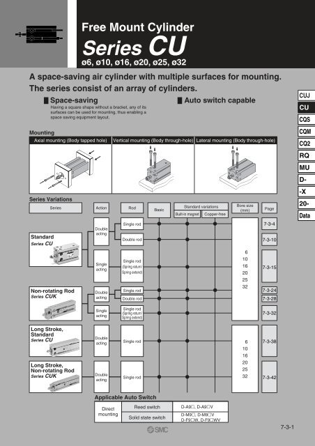
Free Mount CylinderDouble Acting, Single Rod<strong>Series</strong> CUø6, ø10, ø16, ø20, ø25, ø32How to OrderWithout auto switchCU6 30DWith auto switchCDU6 30DF9BWBuilt-in magnet 61016202532Bore size 6 mm10 mm16 mm20 mm25 mm32 mm Number of auto switchesNilS2 pcs.1 pc. Auto switchNil Without auto switch∗ For the applicable auto switch model, refer to the table below.∗ Auto switches are shipped together, (but not assembled).ø6, ø10, ø16ø20, ø25, ø32Standard stroke (mm) 5, 10, 15, 20, 25, 305, 10, 15, 20, 25, 30, 40, 50DAction Double actingApplicable Auto Switch/Refer to page 7-9-1 for further information on auto switches.TypeReedswitchSolid stateswitchSpecial function——Diagnostic indication(2-color indication)ElectricalentryGrommetGrommet∗ Lead wire length symbols: 0.5 m··········NilIndicator lightYesYesWiring(Output)Load voltageAuto switch modelLead wire length (m) ∗ Pre-wire0.5 3 5Applicable loadconnector(Nil) (L) (Z)DC ACPerpendicular In-line3-wireIC— 5 V — A96V A96 — —(NPN equivalent)—circuit2-wire 24 V 12 V 100 V A93V A93 — — — Relay, PLC3-wire (NPN)M9NV M9N IC5 V, 12 V3-wire (PNP)M9PV M9P circuit2-wire12 V —24 V—M9BV M9BRelay,3-wire (NPN)F9NWV F9NW IC PLC5 V, 12 V3-wire (PNP)F9PWV F9PW circuit2-wire12 VF9BWV F9BW —(Example) A93∗ Solid state switches marked with “” are produced upon receipt of order.3 m···········L (Example) A93L5 m···········Z (Example) F9NWZ• Since there are other applicable auto switches than listed, refer to page 7-3-9 for details.• For details about auto switches with pre-wire connector, refer to page 7-9-36.7-3-4
<strong>Series</strong> CUCopper-free20-CU Bore size Stroke DCopper-freeThe type which prevents copper based ions from generating by changingthe copper based materials into electroless nickel plated treatment or noncoppermaterials in order to eliminate the effects by copper based ions orfluororesins over the color cathode ray tube.Minimum Operating PressureBore size (mm)Minimum operating pressureConstructionø660.1210, 160.06(MPa)20, 25, 320.05SpecificationsActionBore size (mm)Maximum operating pressureCushionStrokeAuto switchWith auto switchDouble acting, Single rod6, 10, 16, 20, 25, 321.05 MPaRubber bumperSame as standard model (Refer to page 7-3-4.)Mountableø10ø16 to ø32Component PartsNo.qwertyuDescriptionCylinder tubeHead coverPistonPiston rodBumper ABumper BSnap ringMaterialAluminum alloyBrassAluminum alloyBrassAluminum alloyStainless steelUrethaneUrethaneCarbon tool steelReplacement Parts: Seal KitBore size(mm)1016202532Kit no.CU10D-PSCU16D-PSCU20D-PSCU25D-PSCU32D-PSNoteHard anodizedø6 to ø10, Nickel platedø16 to ø32, Clear chromatedø6 to ø10ø16 to ø32, ChromatedPhosphate coatedContentsSet of nos. above !4, !5, !6∗ Seal kit includes !4, !5, !6. Order the seal kit, based on each bore size.No. Descriptioni Rod end nuto Bushing!0 Magnet holder!1 Magnet!2 Auto switch!3 Piston gasket!4 ∗ Piston seal!5 ∗ Rod seal!6 ∗ GasketMaterialCarbon steelOil-impregnated sintered alloyBrassMagnetic material—NBRNoteNickel platedø67-3-6
Free Mount CylinderDouble Acting, Single Rod<strong>Series</strong> CUDimensions: Double Acting, Single Rodø6, ø10Rod end nut2-ø P through2-M5 x 0.8CUJCUCQSCQM2-ø P throughT counterboreS + StrokeZ + StrokeAuto switchCQ2RQMUD-ø16 to ø32Rod end nut2-ø P through2-M5 x 0.8 (ø32: Rc 1/8)-X20-Rod End Nut/AccessoryDataWidth acrossflats LA'2-ø P throughT counterboreS + StrokeZ + StrokeAuto switchPart no.NTP-006NTP-010NTJ-015ANT-015ANT-02NT-03Material: Carbon steelApplicabled H1 B1 C1bore (mm)61016202532M3 x 0.5M4 x 0.7M5 x 0.8M6 x 1.0M8 x 1.25M10 x 1.251.82.445565.5781013176.48.19.211.515.019.6Bore size(mm)61016202532Bore size(mm)61016202532A A' B C D E GA GB H J K L MM NN P Q QA710111215.519.5R7912162024——12.5141822T1315202632406 depth 4.86 depth 57.6 depth 6.59.3 depth 89.3 depth 911 depth 11.522243240506234681012Without auto switchS Z33 4636 5230 4636 5540 6342 69777910111516.516.5 Note)1921.523101011.512.51312.5With auto switchS Z33 4636 5240 5646 6550 7352 79131616192327101114162024171825303848——56810M3 x 0.5M4 x 0.7M5 x 0.8M6 x 1.0M8 x 1.25M10 x 1.25Note) 5 stroke (CU16-5D): 14.5 mmM3 x 0.5 depth 5M3 x 0.5 depth 5M4 x 0.7 depth 6M5 x 0.8 depth 8M5 x 0.8 depth 8M6 x 1.0 depth 93.23.24.55.55.56.6——49913.5——24.54.54.57-3-7
<strong>Series</strong> CUProper Auto Switch Mounting Position (Detection at stroke end) and Its Mounting HeightD-A9D-M9D-F9W22 (24.5)( ): Denotes the values of D-A93.D-A9VD-M9VD-F9WV5 (7)( ): Denotes the values of D-M9V, D-F9WV.CDU Double Acting, Single RodBore size(mm)61016202532D-A9, D-A9V D-M9, D-F9W D-M9V, D-F9WVA13.512.5162022.523.5B–0.53.54678.5W2.5(5)–1.5(1)–2(0.5)–4(–1.5)–5.5(–3)–6.5(–4)A17.516.5202426.527.5B3.57.58101112.5W6.52.51.50–1.5–2.5A17.516.5202426.527.5B3.57.58101112.5W4.50.5–0.5–2–3.5–4.5Note 1) Negative figures in the table W indicate an auto switch is mounted inward from the edge of thecylinder body.Note 2) In the case of the 5 stroke or the 10 stroke, there are times in which the switch will not turnOFF or 2 switches will turn ON simultaneously due to their movement range. Therefore, setthe position approximately 1 to 4 mm outward from the values given in the table above. Then,perform an operation inspection to make sure that the switches operate normally (if 1 switch isused, make sure that it turns ON and OFF properly; if 2 switches are used, make sure thatboth switches turn ON).Operating RangeAuto switch modelD-A9/A9VD-M9/M9VD-F9W/F9WV652.531062.53.5Bore size (mm)∗ Since this is a guideline including hysteresis, not meant to be guaranteed.(assuming approximately ±30% dispersion.)There may be the case it will vary substantially depending on an ambientenvironment.1693.55.5201156.52512.5573214577-3-8
Free Mount CylinderDouble Acting, Single Rod<strong>Series</strong> CUMounting of Auto SwitchAuto Switch GrooveD-A9/M9/A9V/M9V/F9W/F9WVWatchmakers' screwdriver4-ø4.2Set screw• When tightening an auto switch mountingscrew, use a watchmakers’ screwdriverwith a grip diameter of 5 to 6 mm.• Use a tightening torque of approximately0.10 to 0.20 N·m.When universal mounting cylinders equipped with D-A9 or D-M9auto switches are used, the auto switches could activateunintentionally if the installed distance is less than the dimensionsshown in the table. Therefore, make sure to provide a greaterclearance. Due to unavoidable circumstances, if they must be usedwith less distance than the dimensions given in the table, the cylindersmust be shielded. Therefore, affix a steel plate or a magnetic shieldplate (MU-S025) to the area on the cylinder that corresponds to theadjacent auto switch. (Please contact <strong>SMC</strong> for details.)• Never use BU-1 (Mounting screw for D-9auto switch).(Auto switch may be damaged.)Caution on Proximity InstallationAuto switch mounting screwBU-1Bore size (mm)61016202532Bore size (mm)61016202532AB8.2910.3131518212327253527Mounting pitch l (mm)182033404656CUJCUCQSCQMCQ2RQMUD--X20-DataOther than the applicable auto switches listed in “How to Order”, the following auto switches can bemounted. For detailed specifications, refer to page 7-9-1.Electrical entryType Model (Fetching direction)FeaturesD-A90 Grommet (In-line)Reed switchWithout indicator lightD-A90V Grommet (Perpendicular)∗ Normally closed (NC = b contact), solid state switch (D-F9G/F9H type) are also available. For details, refer to page 7-9-23.7-3-9
Free Mount CylinderDouble Acting, Double Rod<strong>Series</strong> CUWø6, ø10, ø16, ø20, ø25, ø32How to OrderWithout auto switchCUW6 30DWith auto switchCDUW6 30DF9BWBuilt-in magnet Double rod 61016202532Bore size 6 mm10 mm16 mm20 mm25 mm32 mm ActionD Double acting Number of auto switchesNilS2 pcs.1 pc. Auto switchNil Without auto switch∗ For the applicable auto switch model, refer to the table below.∗ Auto switches are shipped together, (but not assembled).ø6, ø10, ø16ø20, ø25, ø32Standard stroke (mm) 5, 10, 15, 20, 25, 305, 10, 15, 20, 25, 30, 40, 50Applicable Auto Switch/Refer to page 7-9-1 for further information on auto switches.TypeReedswitchSolid stateswitchSpecial function——Diagnostic indication(2-color indication)ElectricalentryGrommetGrommet∗ Lead wire length symbols: 0.5 m··········NilIndicator lightYesYesLead wire length (m)∗Pre-wire0.5 3 5 connector(Nil) (L) (Z)Load voltageWiringAuto switch modelApplicable load(Output) DC ACPerpendicular In-line3-wireIC— 5 V — A96V A96 — —(NPN equivalent)circuit—2-wire 24 V 12 V 100 V A93V A93 — — — Relay, PLC3-wire (NPN)M9NV M9N IC5 V, 12 V3-wire (PNP)M9PV M9P circuit2-wire12 V —24 V—M9BV M9BRelay,3-wire (NPN)F9NWV F9NW IC PLC5 V, 12 V3-wire (PNP)F9PWV F9PW circuit2-wire12 VF9BWV F9BW —(Example) A93∗ Solid state switches marked with “” are produced upon receipt of order.3 m···········L (Example) A93L5 m···········Z (Example) F9NWZ• Since there are other applicable auto switches than listed, refer to page 7-3-9 for details.• For details about auto switches with pre-wire connector, refer to page 7-9-36.7-3-10
Free Mount CylinderDouble Acting, Double Rod<strong>Series</strong> CUWSpecificationsBore size (mm)FluidProof pressureMaximum operating pressureMinimum operating pressureAmbient and fluid temperatureLubricationPiston speedCushionRod end threadThread toleranceStroke length tolerance610 16 20 25 32Air1.05 MPa0.7 MPa0.15 MPa 0.10 MPa0.08 MPaWithout auto switch: –10 to 70°C (No freezing)With auto switch: –10 to 60°C (No freezing)Non-lube50 to 500 mm/sRubber bumperMale threadJIS Class 2+1.00 mmCUJCUCQSJIS SymbolDouble acting,Double rodStandard StrokeBore size (mm)6, 10, 1620, 25, 32Minimum Stroke for Auto Switch MountingNo. of autoswitches mounted1 pc.2 pcs.510Standard stroke (mm)5, 10, 15, 20, 25, 305, 10, 15, 20, 25, 30, 40, 50Applicable auto switchD-A9, D-A9V D-M9, D-M9V D-F9W, D-F9WV55510(mm)CQMCQ2RQMUD--XTheoretical Output(N)20-Bore size(mm)Rod size(mm)Piston area(mm 2 )Operating pressure (MPa)0.3 0.50.7Data6321.26.3610.614.810466.019.833.046.216617251.686.012120826479.213218525104121242062883212691207346484Weight /( ): Denotes the values with D-A93.Stroke (mm)Model5 10 15 20 25 3040 50(g)C(D)UW6-D27(32)30(40)34(44)37(47)40(50)44(54)——C(D)UW10-D44(49)49(59)53(63)58(68)62(72)67(77)——C(D)UW16-D74(99)81(111)88(118)95(125)102(132)109(139)——C(D)UW20-D132(165)145(182)158(195)171(208)184(221)197(234)223(260)250(287)C(D)UW25-D240(294)260(319)280(339)300(359)321(380)341(400)381(440)421(480)C(D)UW32-D365(438)394(472)422(500)451(529)479(557)508(586)586(664)622(700)∗ For the auto switch weight, refer to page 7-9-1.Tightening TorqueWhen mounting <strong>Series</strong> CUW, refer to page7-3-5.7-3-11
<strong>Series</strong> CUWConstructionø6With auto switchø10ø16 to 32Component PartsNo.qwertyuiDescriptionCylinder tubeRod coverRod cover retainerPistonPistonPiston rodPiston rodBushingMaterialAluminum alloyAluminum bearing alloyAluminum alloyBrassBrassAluminum alloyStainless steelStainless steelOil-impregnated sintered alloyReplacement Parts: Seal KitKit no.NoteHard anodizedChromatedHard anodizedø6ø6, ø10ø16 to ø32, Chromated10CUW10D-PSø616CUW16D-PS∗ Seal kit includes !5, !6, !7. Order the seal kit, based on each bore size.No.o Bumper!0!1!2!3!4!5 ∗!6 ∗!7 ∗Rod end nutHexagon socket head cap screwMagnetAuto switchPiston gasketPiston sealRod sealGasketDescriptionBore size (mm)20CUW20D-PSMaterialUrethaneCarbon steelCarbon steelMagnetic materialNBR25CUW25D-PSNoteNickel platedNickel plated32CUW32D-PS7-3-12
Free Mount CylinderDouble Acting, Double Rod<strong>Series</strong> CUWDimensions: Double Acting, Double Rodø6, ø10Rod end nut2-øP through2-M5 x 0.8CUJAuto switchCUCQSCQM2-øP through4-øT counterboreS + StrokeZ + 2 x StrokeW + StrokeCQ2RQMUD-ø16 to ø32Rod end nut2-øP through2-M5 x 0.8 (ø32: Rc 1/8)Rod End Nut/Accessory-X20-DataAuto switchWidthacross flats LA'2-øP through4-øT counterboreS + StrokeZ + 2 x StrokeA'W + StrokeWidth acrossflats LPart no.NTP-006NTP-010NTJ-015ANT-015ANT-02NT-03Applicable boresize (mm)61016202532Material: Carbon steeldM3 x 0.5M4 x 0.7M5 x 0.8M6 x 1.0M8 x 1.25M10 x 1.25H1 B1 C11.82.445565.5781013176.48.19.211.515.019.6Bore size(mm)61016202532Bore size(mm)61016202532A710111215.519.5R7912162024A'——12.5141822SA667.59910B131520263240TC2224324050626 depth 4.86 depth 57.6 depth 6.59.3 depth 89.3 depth 911 depth 11.5D34681012W131616192327E77791011GA1516.516.5 Note)1921.523GB16161921.52222.5H131616192327Without auto switch With auto switchS383630364042Z707469.58395106S383640465052Z707479.593105116J K L MMNN17 — M3 x 0.518 — M4 x 0.725 5 M5 x 0.830 6 M6 x 1.038 8 M8 x 1.2548 10 M10 x 1.25Note) 5 stroke (CUW16-5D): GA = 14.5101114162024M3 x 0.5 depth 5M3 x 0.5 depth 5M4 x 0.7 depth 6M5 x 0.8 depth 8M5 x 0.8 depth 8M6 x 1.0 depth 9P3.23.24.55.55.56.6Q——49913.5QA——24.54.54.57-3-13
<strong>Series</strong> CUWProper Auto Switch Mounting Position (Detection at stroke end) and Its Mounting HeightD-A9D-M9D-F9W22 (24.5)( ): Denotes the values of D-A93.D-A9VD-M9VD-F9WV5 (7)( ): Denotes the values of D-M9V, D-F9WV.Bore size(mm)61016202532D-A9, D-A9V D-M9, D-F9W D-M9V, D-F9WVA13.512.5162022.523.5B5.59.511.5151618.5W–3.5(–1)–7.5(–5)–9.5(–7)–13(–10.5)–14.5(–12)–16.5(–14)A17.516.5202426.527.5B9.513.515.5192022.5W0.5–3.55.5–9–10.5–12.5A17.516.5202426.527.5B9.513.515.5192022.5W–1.5–5.5–7.5–11–12.5–14.5Note 1) Negative figures in the table W indicate an auto switch is mounted inward from the edge of thecylinder body.Note 2) In the case of the 5 stroke or the 10 stroke, there are times in which the switch will not turnOFF or 2 switches will turn ON simultaneously due to their movement range. Therefore, setthe position approximately 1 to 4 mm outward from the values given in the table above. Then,perform an operation inspection to make sure that the switches operate normally (if 1 switch isused, make sure that it turns ON and OFF properly; if 2 switches are used, make sure thatboth switches turn ON).Note 3) ( ) in column W is the dimensions of D-A93.7-3-14
Free Mount CylinderSingle Acting, Single Rod, Spring Return/Extend<strong>Series</strong> CUø6, ø10, ø16, ø20, ø25, ø32Without auto switchWith auto switchBuilt-in magnet 61016202532CU 10 15 SCDU 10 15 SBore size 6 mm10 mm16 mm20 mm25 mm32 mmStandard stroke (mm) ø6, ø10, ø165, 10, 15ø20, ø25, ø32How to Order ActionSTF9BW Auto switchNil Without auto switch∗ For the applicable auto switch model, refer to the table below.∗ Auto switches are shipped together, (but not assembled).Single acting, Spring returnSingle acting, Spring extend Number of auto switchesNilS2 pcs.1 pc.CUJCUCQSCQMCQ2RQMUD--X20-DataApplicable Auto Switch/Refer to page 7-9-1 for further information on auto switches.TypeReedswitchSolid stateswitchSpecial function——Diagnostic indication(2-color indication)ElectricalentryGrommetGrommet∗ Lead wire length symbols: 0.5 m··········NilIndicator lightYesYesLead wire length (m) ∗ Pre-wire0.5 3 5 connector(Nil) (L) (Z)Load voltageWiringAuto switch modelApplicable load(Output) DC ACPerpendicular In-line3-wireIC— 5 V — A96V A96 — —(NPN equivalent)circuit—2-wire 24 V 12 V 100 V A93V A93 — — — Relay, PLC3-wire (NPN)M9NV M9N IC5 V, 12 V3-wire (PNP)M9PV M9P circuit2-wire12 V 24 V—M9BV M9B— Relay,3-wire (NPN)F9NWV F9NW IC PLC5 V, 12 V3-wire (PNP)F9PWV F9PW circuit2-wire12 VF9BWV F9BW —(Example) A93∗ Solid state switches marked with “” are produced upon receipt of order.3 m···········L (Example) A93L5 m···········Z (Example) F9NWZ• Since there are other applicable auto switches than listed, refer to page 7-3-9 for details.• For details about auto switches with pre-wire connector, refer to page 7-9-36.7-3-15
<strong>Series</strong> CUJIS SymbolSingle acting,Spring returnSingle acting,Spring extendSpecificationsBore size (mm)FluidProof pressureMaximum operating pressureMinimum operating pressureAmbient and fluid temperatureLubricationPiston speedCushionRod end threadThread toleranceStroke length toleranceNote) ø6 with auto switch type: One side rubber bumperStandard StrokeBore size (mm)6, 10, 16,20, 25, 32Standard stroke (mm)5, 10, 15610 16 20 25 32Air1.05 MPa0.7 MPa0.2 MPa 0.15 MPa0.13 MPaWithout auto switch: –10 to 70°C (No freezing)With auto switch: –10 to 60°C (No freezing)Non-lube50 to 500 mm/sRubber bumperMale threadJIS Class 2+1.00 mmNote)Minimum Stroke for Auto Switch MountingNo. of autoswitches mountedApplicable auto switchD-A9, D-A9V D-M9, D-M9V D-F9W, D-F9WV(mm)1 pc.2 pcs.51055510Made to Order Specifications(For details, refer to page 7-10-1.)SymbolSpecifications-XC18 NPT finish piping port-XC22 Fluoro rubber sealsTheoretical OutputActionBore sizeOperating pressure (MPa)(mm)0.30.56104.9916.710.732.4Spring return (S)1645.686.3207313625326101192072.8612.92183687.1026.1Spring extend (T)1637.271.82058111253295173178312For the reactive force of spring return, refer to page 7-12-3.0.716.348.112619931652911.339.3106164260450(N)Weight/( ): Denotes the values with D-A93.(g)Model5C(D)U6-S,T22(27)C(D)U10-S,T36(41)C(D)U16-S,T50(75)C(D)U20-S,T95(128)C(D)U25-S,T176(230)C(D)U32-S,T262(335)∗ For the weight of auto switch, refer to page 7-9-1.Stroke (mm)1025(35)40(50)56(86)106(143)193(252)286(364)1528(38)48(58)71(101)133(170)235(294)347(425)Tightening TorqueWhen mounting a CU single acting series,refer to page 7-3-5.7-3-16
Free Mount CylinderSingle Acting, Single Rod, Spring Return/Extend<strong>Series</strong> CUConstructionSingle acting, Spring returnWith auto switchCUJCUø10ø16 to ø32CQSCQMCQ2RQMUD--X20-DataComponent PartsNo.qwertyuiDescriptionCylinder tubeHead coverPistonPistonPiston rodBumper ABumper BReturn springMaterialAluminum alloyBrassAluminum alloyBrassAluminum alloyBrassStainless steelUrethaneUrethanePiano wireReplacement Parts: Seal KitKit no.NoteHard anodizedø6 to ø10, Nickel platedø16 to ø32, Clear chromatedø6 to ø10ø16 to ø32, Chromatedø10Zinc chromated10CU10S-PS∗ Seal kit includes !8, !9. Order the seal kit, based on each bore size.16CU16S-PSNo. Descriptiono Spring seat!0 Spring seat!1 Snap ring!2 Rod end nut!3 Bushing!4 Magnet holder!5 Magnet!6 Auto switch!7 Piston gasket!8 ∗ Piston seal!9 ∗ GasketBore size (mm)20CU20S-PSMaterialBrassBrassCarbon tool steelCarbon steelOil-impregnated sintered alloyBrassMagnetic material—NBR25CU25S-PSNotePhosphate coatedNickel platedø632CU32S-PS7-3-17
Free Mount CylinderSingle Acting, Single Rod, Spring Return/Extend<strong>Series</strong> CUDimensions: Single Acting, Spring Returnø6, ø10Rod end nut2-øP through Bleed port M5 x 0.8CUJCUCQSCQM2-øP through4-øT counterboreAuto switchCQ2RQMUø16 to ø32Rod end nut2-øP throughBleed portM5 x 0.8 (ø32: Rc 1/8)Rod End Nut/AccessoryD--X20-DataWidth across flats L2-øP through4-øT counterboreAuto switchPart no.NTP-006NTP-010NTJ-015ANT-015ANT-02NT-03Applicable boresize (mm)61016202532Material: Carbon steeldM3 x 0.5M4 x 0.7M5 x 0.8M6 x 1.0M8 x 1.25M10 x 1.25H1 B1 C11.82.445565.5781013176.48.19.211.515.019.6Bore size(mm)61016202532A710111215.519.5A'——12.5141822B131520263240C222432405062D34681012E77791011GA1516.516.51921.523GB101011.512.51312.5H131616192327J101114162024K171825303848L——56810MMM3 x 0.5M4 x 0.7M5 x 0.8M6 x 1.0M8 x 1.25M10 x 1.25NNM3 x 0.5 depth 5M3 x 0.5 depth 5M4 x 0.7 depth 6M5 x 0.8 depth 8M5 x 0.8 depth 8M6 x 1.0 depth 9P3.23.24.55.55.56.6Q——49913.5QA——24.54.54.5R7912162024T6 depth 4.86 depth 57.6 depth 6.59.3 depth 89.3 depth 911 depth 11.5Bore size(mm)610162025325 st384135414547S10 st434640465052Without auto switchWith auto switchZ S Z15 st4856505660625 st51575160687410 st56625665737915 st6172667583895 st38414551555710 st43465056606215 st4856606670725 st51576170788410 st56626675838915 st6172768593997-3-19
<strong>Series</strong> CUDimensions: Single Acting, Spring Extendø6, ø10Rod end nut2-øP throughM5 x 0.8Plug with fixed orificeH + Stroke2-øP through4-øT counterboreAuto switchø16 to ø32Rod end nut2-øP throughM5 x 0.8 (ø32: Rc 1/8)Plug with fixed orificeRod End Nut/AccessoryMaterial: Carbon steelWidth across flats LA'H + Stroke2-øP through4-øT counterboreAuto switchPart no.NTP-006NTP-010NTJ-015ANT-015ANT-02NT-03Applicable boresize (mm)61016202532dM3 x 0.5M4 x 0.7M5 x 0.8M6 x 1.0M8 x 1.25M10 x 1.25H1 B1 C11.82.445565.5781013176.48.19.211.515.019.6Bore size(mm)61016202532A710111215.519.5A'——12.5141822B131520263240C222432405062D34681012E77791011GA1516.516.51921.523GB101011.512.51312.5H131616192327J101114162024K171825303848L——56810MMM3 x 0.5M4 x 0.7M5 x 0.8M6 x 1.0M8 x 1.25M10 x 1.25NNM3 x 0.5 depth 5M3 x 0.5 depth 5M4 x 0.7 depth 6M5 x 0.8 depth 8M5 x 0.8 depth 8M6 x 1.0 depth 9P3.23.24.55.55.56.6Q——49913.5QA——24.54.54.5R7912162024T6 depth 4.86 depth 57.6 depth 6.59.3 depth 89.3 depth 911 depth 11.5V——3.5555Bore size(mm)610162025325 st384145414547S10 st434650465052Without auto switch15 st4856605660625 st566266657379Z10 st66727675838915 st76879190981045 st384145515557S10 st434650566062With auto switch15 st4856606670725 st566266758389Z10 st66727685939915 st7687911001081147-3-20
Free Mount CylinderSingle Acting, Single Rod, Spring Return/Extend<strong>Series</strong> CUProper Auto Switch Mounting Position and Its Mounting Height: Single Acting, Spring ReturnD-A9D-M9D-M9W22 (24.5)D-A9VD-M9VD-F9WV22 (20)( ): Denotes the values of D-A93.CUJCUCQSCQMCQ2RQMUD--X20-Data5 (7)( ): Denotes the values of D-M9V, D-F9WV.Single Acting, Spring ReturnStrokeD-A9, D-A9V D-M9, D-F9W D-M9V, D-F9WVA B W A B W A B WAll stroke 13.5 0 2.5(5) 17.5 4 6.5 17.5 4 4.55, 1012.516.516.53.5 –1.5(1)7.5 2.51517.521.521.55, 101620204 –2(0.5)8 2152125255, 102024246 –4(–1.5)10 0152529295, 1022.57 –5.5(–3) 26.511 –1.5 26.51527.531.531.55, 1023.527.527.58.5 –6.5(–4)12.5 –2.51528.532.532.57.58101112.50.5–0.5–2–3.5–4.5Note 1) Negative figures in the table W indicate an auto switch is mounted inward from the edge of thecylinder body.Note 2) In the case of the 5 stroke or the 10 stroke, there are times in which the switch will not turn OFF or2 switches will turn ON simultaneously due to their movement range. Therefore, set the positionapproximately 1 to 4 mm outward from the values given in the table above. Then, perform anoperation inspection to make sure that the switches operate normally (if 1 switch is used, makesure that it turns ON and OFF properly; if 2 switches are used, make sure that both switches turnON).Note 3) ( ) in column W is the dimensions of D-A93.Bore size(mm)610162025327-3-21
<strong>Series</strong> CUProper Auto Switch Mounting Position and Its Mounting Height: Single Acting, Spring ExtendD-A9D-M9D-F9W22 (24.5)( ): Denotes the values of D-A93.D-A9VD-M9VD-F9WV22 (20)5 (7)( ): Denotes the values of D-M9V, D-F9WV.Single Acting, Spring ExtendBore size(mm)61016202532StrokeAll stroke5, 10155, 10155, 10155, 10155, 1015A B W10.512.51620D-A9, D-A9V22.523.51.53.58.5496117128.513.50.5(3)–1.5(1)–6.5(–4)–2(0.5)–7(–4.5)–4(–1.5)–9(–6.5)–5.5(–3)–10.5(–8)–6.5(–4)–11.5(–9)D-M9, D-F9WA B W14.5 5.5 4.5Note 1) Negative figures in the table W indicate an auto switch is mounted inward from the edge of thecylinder body.Note 2) In the case of the 5 stroke or the 10 stroke, there are times in which the switch will not turn OFFor 2 switches will turn ON simultaneously due to their movement range. Therefore, set theposition approximately 1 to 4 mm outward from the values given in the table above. Then,perform an operation inspection to make sure that the switches operate normally (if 1 switch isused, make sure that it turns ON and OFF properly; if 2 switches are used, make sure that bothswitches turn ON).Note 3) ( ) in column W is the dimensions of D-A93.16.5202426.527.57.512.58131015111612.517.52.5–2.52–30–5–1.5–6.5–2.5–7.5D-M9V, D-F9WVA B W14.5 5.5 2.516.5202426.527.57.512.58131015111612.517.50.5–4.50–5–2–7–3.5–8.5–4.5–9.57-3-22
Free Mount Cylinder: Non-rotating Rod TypeDouble Acting, Single Rod<strong>Series</strong> CUKø6, ø10, ø16, ø20, ø25, ø32How to OrderWithout auto switchCUK6 30DWith auto switchCDUK6 30DF9BWBuilt-in magnet Non-rotating rod type 61016202532Bore size 6 mm10 mm16 mm20 mm25 mm32 mm ActionD Double acting Number of auto switchesNilS2 pcs.1 pc. Auto switchNil Without auto switch∗ For the applicable auto switch model, refer to the table below.∗ Auto switches are shipped together, (but not assembled).ø6, ø10, ø16ø20, ø25, ø32Standard stroke (mm) 5, 10, 15, 20, 25, 305, 10, 15, 20, 25, 30, 40, 50Applicable Auto Switch/Refer to page 7-9-1 for further information on auto switches.TypeReedswitchSolid stateswitchSpecial function——Diagnostic indication(2-color indication)ElectricalentryGrommetGrommetIndicator lightYesYes∗ Lead wire length symbols: 0.5 m··········Nil (Example) A933 m···········L (Example) A93L5 m···········Z (Example) F9NWZ• Since there are other applicable auto switches than listed, refer to page 7-3-5 for details.• For details about auto switches with pre-wire connector, refer to page 7-9-36.Load voltageLead wire length (m) ∗WiringAuto switch modelPre-wire(Output)0.5 3 5Applicable loadDC ACconnectorPerpendicular In-line (Nil) (L) (Z)3-wireIC— 5 V — A96V A96 — —(NPN equivalent)—circuit2-wire 24 V 12 V 100 V A93V A93 — — — Relay, PLC3-wire (NPN)M9NV M9N 5 V, 12 VIC3-wire (PNP)M9PV M9P circuit2-wire12 V —24 V—M9BV M9BRelay,3-wire (NPN)F9NWV F9NW IC PLC5 V, 12 V3-wire (PNP)F9PWV F9PW circuit2-wire12 VF9BWV F9BW —∗ Solid state switches marked with “” are produced upon receipt of order.7-3-24
Free Mount Cylinder: Non-rotating Rod TypeDouble Acting, Single Rod<strong>Series</strong> CUKJIS SymbolDouble acting,Single rod typeSymbol-XB6-XB7-XB9-XB13-XC18-XC19-XC22-XC34Made to Order Specifications(For details, refer to page 7-10-1.)CautionSpecificationsHeat resistant cylinder (150°C)Cold resistant cylinderLow speed cylinder (10 to 50 mm/s)Low speed cylinder (5 to 50 mm/s)NPT finish piping portIntermediate stroke (Compliant for spacer)Fluoro rubber sealsRod does not extend beyond non-rotating platePrecautionsBe sure to read before handling.For Safety Instructions and ActuatorPrecautions, refer to pages 7-13-3 to7-13-6.Operating Precautions1. Do not place your fingers in the clearancebetween the non-rotating plate and thecylinder tube.Your fingers could get caught between thenon-rotating plate and the cylinder tube whenthe piston rod retracts. Therefore, never placeyour finger in this area.Because the cylinder outputs a great force, itcould lead to injury if precautions are nottaken to prevent your fingers from gettingcaught.2. When using the non-rotating style, make surethat rotational torque is not applied to thepiston rod. If rotational torque must beapplied due to unavoidable circumstances,make sure to use it at the allowable rotationaltorque or less, which is shown in the table onthe right.SpecificationsBore size (mm)FluidProof pressureMaximum operating pressureMinimum operating pressureAmbient and fluid temperatureLubricationPiston speedCushionRod end threadThread toleranceStroke length toleranceRod non-rotating accuracyNote) No load: Rod at retractedStandard StrokeBore size (mm)6, 10, 1620, 25, 32Minimum Stroke for Auto Switch MountingNo. of autoswitches mounted1 pc.2 pcs.Standard stroke (mm)5, 10, 15, 20, 25, 305, 10, 15, 20, 25, 30, 40, 50510Weight /( ): Denotes the values with D-A93.Bore size (mm)C(D)UK6-DC(D)UK10-DC(D)UK16-DC(D)UK20-DC(D)UK25-DC(D)UK32-DApplicable auto switch55510Stroke (mm)5 10 15 20 25 30 40 5028(33)43(48)60(85)113(147)212(266)331(404)Note)31(41)47(57)66(96)124(164)229(288)357(435)34(44)51(61)72(102)136(176)246(305)383(461)∗ For the auto switch weight, refer to page 7-9-1.Allowable Rotational TorqueBore size (mm) 6Allowable rotational torque(N·m)0.0015Tightening TorqueTheoretical Output60.15 MPa 0.10 MPa0.08 MPaWithout auto switch: –10 to 70°C (No freezing)With auto switch: –10 to 60°C (No freezing)D-A9, D-A9V D-M9, D-M9V D-F9W, D-F9WV100.02When mounting <strong>Series</strong> CUK, refer topage 7-3-5.Specifications are the same as CU seriesdouble acting, single rod. Refer to page7-3-5.37(47)55(65)78(108)148(188)263(322)409(487)160.0410 16 20 25±0.8° ±0.5°40(50)59(69)84(114)160(200)280(339)435(513)Air1.05 MPa0.7 MPaNon-lube50 to 500 mm/sRubber bumperMale threadJIS Class 2+1.00 mmFor long stroke, refer topage 7-3-42.200.1043(53)63(73)90(120)172(211)297(356)461(539)———195(235)335(390)513(591)250.1532(mm)———219(260)370(424)565(643)320.20(g)Auto Switch Mounting PositionFor the auto switch mounting position of<strong>Series</strong> CDUK, refer to page 7-3-8, sincespecifications are the same as standardtype, double acting, single rod type.CUJCUCQSCQMCQ2RQMUD--X20-Data7-3-25
Free Mount Cylinder: Non-rotating Rod TypeDouble Acting, Single Rod<strong>Series</strong> CUKDimensions: Non-rotating Rod Type; Double Acting, Single Rodø6, ø10Rod end nut2-øP through2-M5 x 0.8CUJCUCQSø16 to ø32Rod end nut2-øP through2-øP through4-øT counterbore Auto switchS + StrokeZ + Stroke2-M5 x 0.8 (ø32: Rc 1/8)CQMCQ2RQMUD--X20-DataWidth across flats LA'2-øP through4-øT counterboreS + StrokeZ + StrokeAuto switchRod End Nut/AccessoryMaterial: Carbon steelPart no.NTP-006NTP-010NTJ-015ANT-015ANT-02NT-03Applicable boresize (mm)61016202532dM3 x 0.5M4 x 0.7M5 x 0.8M6 x 1.0M8 x 1.25M10 x 1.25H1 B1 C11.82.445565.5781013176.48.19.211.515.019.6Bore size(mm)61016202532A710111215.519.5A'——12.5141822B131520263240C222432405062D34681012E77791011F88881012FL91217202229FK111213162024FY20.522283343.551.5GA1516.516.5 Note)1921.523GB101011.512.51312.5H182126293342J101114162024K171825303848L——56810MMM3 x 0.5M4 x 0.7M5 x 0.8M6 x 1.0M8 x 1.25M10 x 1.25Bore size(mm)610162025NN32M3 x 0.5 depth 5M3 x 0.5 depth 5M4 x 0.7 depth 6M5 x 0.8 depth 8M5 x 0.8 depth 8M6 x 1.0 depth 93.23.24.55.55.56.6Note) 5 stroke (CUK16-5D): GA = 14.5PQ——49913.5QA——24.54.54.5R7912162024T6 depth 4.86 depth 57.6 depth 6.59.3 depth 89.3 depth 911 depth 11.5Y10.511.515.519.524.530.5Without auto switch With auto switchS333630364042Z515756657384S333640465052Z5157667583947-3-27
Free Mount Cylinder: Non-rotating Rod TypeDouble Acting, Double Rod<strong>Series</strong> CUKWø6, ø10, ø16, ø20, ø25, ø32How to OrderWithout auto switchCUKW6 30DWith auto switchCDUKW6 30DF9BW61016202532Bore size 6 mm10 mm16 mm20 mm25 mm32 mmBuilt-in magnet Non-rotating rod type ø6, ø10, ø16ø20, ø25, ø32Double rod Standard stroke (mm) 5, 10, 15, 20, 25, 305, 10, 15, 20, 25, 30, 40, 50 ActionD Double acting Number of auto switchesNilS2 pcs.1 pc. Auto switchNil Without auto switch∗ For the applicable auto switch model, refer to the table below.∗ Auto switches are shipped together, (but not assembled).Applicable Auto Switch/Refer to page 7-9-1 for further information on auto switches.TypeReedswitchSolid stateswitchSpecial function——Diagnostic indication(2-color indication)ElectricalentryGrommetGrommet∗ Lead wire length symbols: 0.5 m··········Nil (Example) A933 m···········L (Example) A93L5 m···········Z (Example) F9NWZIndicator lightYesYes• Since there are other applicable auto switches than listed, refer to page 7-3-9 for details.• For details about auto switches with pre-wire connector, refer to page 7-9-36.Lead wire length (m) ∗ Pre-wire0.5 3 5 connector(Nil) (L) (Z)Load voltageWiringAuto switch model(Output)Applicable loadDC ACPerpendicular In-line3-wireIC— 5 V — A96V A96 — —(NPN equivalent)—circuit2-wire 24 V 12 V 100 V A93V A93 — — — Relay, PLC3-wire (NPN)M9NV M9N 5 V, 12 VIC3-wire (PNP)M9PV M9P circuit2-wire12 V —24 V—M9BV M9BRelay,3-wire (NPN)F9NWV F9NW IC PLC5 V, 12 V3-wire (PNP)F9PWV F9PW circuit2-wire12 VF9BWV F9BW —∗ Solid state switches marked with “” are produced upon receipt of order.7-3-28
Free Mount Cylinder: Non-rotating Rod TypeDouble Acting, Double Rod<strong>Series</strong> CUKWSpecificationsBore size (mm)FluidProof pressureMaximum operating pressureMinimum operating pressureAmbient and fluid temperatureLubricationPiston speedCushionRod end threadThread toleranceStroke length toleranceRod non-rotating accuracyNote)Note) No load: Rod in the non-rotating plate side at retracted610 16 20 25Air1.05 MPa0.7 MPa0.18 MPa 0.13 MPa 0.11 MPaWithout auto switch: –10 to 70°C (No freezing)With auto switch: –10 to 60°C (No freezing)Non-lube50 to 500 mm/sRubber bumperMale threadJIS Class 2+1.00mm±0.8° ±0.5°32CUJCUCQSCQMStandard StrokeBore size (mm)6, 10, 1620, 25, 32Standard stroke (mm)5, 10, 15, 20, 25, 305, 10, 15, 20, 25, 30, 40, 50CQ2RQMUD-JIS SymbolNon-rotating rodMinimum Stroke for Auto Switch MountingNo. of autoswitches mountedApplicable auto switchD-A9, D-A9V D-M9, D-M9V D-F9W, D-F9WV(mm)-X20-1 pc.2 pcs.51055510DataWeight /( ): Denotes the values with D-A93.(g)Stroke (mm)Model5 10 15 20 25 30 40 50C(D)UKW6-D33(38)36(46)40(50)43(53)46(56)50(60)——C(D)UKW10-D51(56)56(66)60(70)65(75)69(79)74(84)——C(D)UKW16-D84(109)91(121)98(128)105(135)112(142)119(149)——C(D)UKW20-D150(185)163(203)177(217)191(231)205(245)219(259)246(286)275(315)C(D)UKW25-D276(330)296(355)316(375)336(395)357(416)377(436)421(476)462(516)C(D)UKW32-D434(507)465(543)495(573)526(604)556(634)587(665)669(747)709(787)∗ For the auto switch weight, refer to page 7-9-1.Theoretical OutputSpecifications are the same as doubleacting, double rod (<strong>Series</strong> CUW). Referto page 7-3-11.Allowable Rotational TorqueEnsure that rotational torque is notapplied to the piston rod of <strong>Series</strong>CUKW. If rotational torque are appliedunavoidably, refer to page 7-3-25.Tightening TorqueWhen mounting <strong>Series</strong> CUKW, refer topage 7-3-5.Auto Switch Mounting PositionFor the auto switch mounting position of<strong>Series</strong> CUKW, refer to page 7-3-14,since specifications are the same asdouble acting, double rod type.7-3-29
<strong>Series</strong> CUKWConstructionø6With auto switchSection AAø10Section AAø16 to ø32Section AAComponent PartsNo.qwerDescriptionCylinder tubeRod coverRod cover retainerPistonMaterialNoteHard anodizedNo.!2!3!4!5tyuio!0!1PistonPiston rodPiston rodBushingBumperRod end nutHexagon socket head cap screwAluminum alloyAluminum bearing alloyAluminum alloyBrassBrassAluminum alloyStainless steelStainless steelOil-impregnated sintered alloyUrethaneCarbon steelCarbon steelReplacement Parts: Seal KitKit no.ChromatedHard anodizedø6ø6, ø10ø16 to ø32, Chromated10CUW10D-PSø6Nickel platedNickel plated16CUW16D-PS∗ Seal kit includes @0, @1, @2. Order the seal kit, based on each bore size.!6!7!8!9@0@1@2DescriptionMagnetAuto switchNon-rotating plateGuide rodBushingHexagon socket head cap screwHexagon socket head set screwPiston gasketPiston sealRod sealGasketBore size (mm)20CUW20D-PSMaterialMagnetic material—Aluminum alloyStainless steelOil-impregnated sintered alloyCarbon steelCarbon steelNBR25CUW25D-PSNoteNickel platedBlack zinc chromatedBlack zinc chromated32CUW32D-PS7-3-30
Free Mount Cylinder: Non-rotating Rod TypeDouble Acting, Double Rod<strong>Series</strong> CUKWDimensions: Non-rotating Rod Type; Double Acting, Double Rodø6, ø10Rod end nut2-øP through2-M5 x 0.8CUJCUCQSCQM2-øP through4-øT counterboreCQ2S + StrokeZ + 2 x StrokeW + StrokeRQø16 to ø32Rod end nut2-øP through2-M5 x 0.8 (ø32: Rc 1/8)MUD--X20-Auto switchDataWidth across flats L2-øP through4-øT counterboreA'S + StrokeW + StrokeZ + 2 x StrokeRod End Nut/AccessoryWidth across flats LPart no.NTP-006NTP-010NTJ-015ANT-015ANT-02NT-03Applicable boresize (mm)61016202532Material: Carbon steeldM3 x 0.5M4 x 0.7M5 x 0.8M6 x 1.0M8 x 1.25M10 x 1.25H1 B1 C11.82.445565.5781013176.48.19.211.515.019.6Bore size(mm)61016202532A710111215.519.5A'——12.5141822B131520263240C222432405062D34681012E77791011F88881012FL91217202229FK111213162024FY20.522283343.551.5GA1516.516.5 Note)1921.523GB16161921.52222.5H182126293342J101114162024L——56810MMM3 x 0.5M4 x 0.7M5 x 0.8M6 x 1.0M8 x 1.25M10 x 1.25Bore size(mm)61016202532P3.23.24.55.55.56.6Q——49913.5QA——24.54.54.5R7912162024Note) 5 stroke (CUKW16-5D): GA = 14.5SA667.59910T6 depth 4.86 depth 57.6 depth 6.59.3 depth 89.3 depth 911 depth 11.5W131616192327Y10.511.515.519.524.530.5Without auto switch With auto switchS383630364042Z757979.593105121S383640465052Z757989.51031151317-3-31
Free Mount Cylinder: Non-rotating Rod TypeSingle Acting, Single Rod, Spring Return/Extend<strong>Series</strong> CUKø6, ø10, ø16, ø20, ø25, ø32How to Order15CUK 10 SNon-rotating rod type CDUK 10Built-in magnet 15 S F9BWWithout auto switchWith auto switch Number of auto switchesNilS Auto switch2 pcs.1 pc.61016202532Bore size 6 mm10 mm16 mm20 mm25 mm32 mmStandard stroke (mm) ø6, ø10, ø16ø20, ø25, ø325, 10, 15 ActionSTNil Without auto switch∗ For the applicable auto switch model, refer to the table below.∗ Auto switches are shipped together, (but not assembled).Single acting, Spring returnSingle acting, Spring extendApplicable Auto Switch/Refer to page 7-9-1 for further information on auto switches.TypeReedswitchSolid stateswitchSpecial function——Diagnostic indication(2-color indication)ElectricalentryGrommetGrommet∗ Lead wire length symbols: 0.5 m··········NilIndicator lightYesYesLead wire length (m) ∗ Pre-wire0.5 3 5 connector(Nil) (L) (Z)Load voltageWiringAuto switch modelApplicable load(Output)DC ACPerpendicular In-line3-wireIC— 5 V — A96V A96 — —(NPN equivalent)—circuit2-wire 24 V 12 V 100 V A93V A93 — — — Relay, PLC3-wire (NPN)M9NV M9N 5 V, 12 VIC3-wire (PNP)M9PV M9P circuit2-wire12 V —24 V—M9BV M9BRelay,3-wire (NPN)F9NWV F9NW IC PLC5 V, 12 V3-wire (PNP)F9PWV F9PW circuit2-wire12 VF9BWV F9BW —(Example) A93∗ Solid state switches marked with “” are produced upon receipt of order.3 m···········L (Example) A93L5 m···········Z (Example) F9NWZ• Since there are other applicable auto switches than listed, refer to page 7-3-9 for details.• For details about auto switches with pre-wire connector, refer to page 7-9-36.7-3-32
Free Mount Cylinder: Non-rotating Rod TypeSingle Acting, Single Rod, Spring Return/Extend<strong>Series</strong> CUKSpecificationsJIS SymbolSingle acting,Spring returnSingle acting,Spring extendBore size (mm)6FluidProof pressureMaximum operating pressureMinimum operating pressureAmbient and fluid temperatureLubricationPiston speedCushion (1)Rod end threadThread toleranceStroke length toleranceRod non-rotating accuracy (2)Note 1) ø6: With auto switch, single rubber bumperNote 2) No load: Rod at retractedStandard StrokeBore size (mm)6, 10, 16,20, 25, 32Standard stroke (mm)5, 10, 15Minimum Stroke for Auto Switch MountingNo. of autoswitches mounted1 pc.2 pcs.51010 16 20 25Air1.05 MPa0.7 MPa0.23 MPa 0.18 MPa 0.16 MPaNon-lube50 to 500 mm/sRubber bumper on both endsMale threadJIS Class 2±0.8° ±0.5°Applicable auto switchD-A9, D-A9V D-M9, D-M9V D-F9W, D-F9WV55+1.00 mm51032Without auto switch: –10 to 70°C (No freezing)With auto switch: –10 to 60°C (No freezing)(mm)CUJCUCQSCQMCQ2RQMUD--X20-DataSymbol-XC18-XC22-XC34Made to Order Specifications(For details, refer to page 7-10-1.)SpecificationsNPT finish piping portFluoro rubber sealsRod does not extend beyond non-rotating plateWeight /( ): Denotes the values with D-A93Stroke (mm)Model5 10 15283134C(D)UK6- ST (33)(41)(44)434755C(D)UK10-S T (48)(57)(65)606681C(D)UK16-S T (85)(90)(111)113124153C(D)UK20-S T (147)(164)(193)212229271C(D)UK25-S T (266)(288)(330)331357422C(D)UK32-ST(404)(435)(500)∗ For the auto switch weight, refer to page 7-9-1.Tightening TorqueWhen mounting a CUK single actingseries, refer to page 7-3-5.Theoretical OutputSpecifications are the same as singleacting, spring return/spring extend type(<strong>Series</strong> CU). Refer to page 7-3-16.Spring Reaction ForceFor “Spring Reaction Force”, refer to page7-12-2.(g)Auto Switch Mounting PositionFor the auto switch mounting position ofCDUK series single acting, springreturn/spring extend, refer to page 7-3-21to 22, since specification are the same asstandard type, single acting, springreturn/spring extend type.Allowable Rotational TorqueMake sure that rotational torque is notapplied to the piston rod of the CUKseries single acting type cylinder. If therotation torque were applied unavoidably,refer to page 7-3-25.7-3-33
<strong>Series</strong> CUKConstructionSingle acting, Spring returnWith auto switchø6Section AAø10Section AAø16 to ø32Section AAComponent PartsNo. Description MaterialNoteNo.q Cylinder tube Aluminum alloy Hard anodized!1weHead coverPistonBrassBrassø6 to ø10, Nickel platedø6 to ø10!2!4Aluminum alloyAluminum alloyø16 to ø32, Clear chromatedø16 to ø32, Chromated!3!5rtyuio!0PistonPiston rodBumper ABumper BReturn springSpring seatSpring seatBrassStainless steelUrethaneUrethanePiano wireBrassBrassø10Zinc chromated!6!7!8!9@0@1@2@3 ∗@4 ∗Replacement Parts: Seal Kit7-3-34Kit no.10CU10S-PS∗ Seal kit includes @3, @4. Order the seal kit, based on each bore size.16CU16S-PSDescriptionSnap ringRod end nutBushingMagnet holderMagnetAuto switchNon-rotating plateGuide rodBushingHexagon socket head cap screwHexagon socket head set screwPiston gasketPiston sealGasketBore size (mm)20CU20S-PSMaterialCarbon tool steelCarbon steelOil-impregnated sintered alloyBrassMagnetic material—Aluminum alloyStainless steelOil-impregnated sintered alloyCarbon steelCarbon steelNBR25CU25S-PSNotePhosphate coatedNickel platedø6Nickel platedBlack zinc chromatedBlack zinc chromated32CU32S-PS
Free Mount Cylinder: Non-rotating Rod TypeSingle Acting, Single Rod, Spring Return/Extend<strong>Series</strong> CUKConstructionSingle acting, Spring extendø6With auto switchCUJCUSection AAø10Section AAø16 to ø32CQSCQMCQ2RQMUD--X20-DataSection AAComponent PartsNo.qwertyuio!0!1DescriptionCylinder tubeHead coverPistonPistonPiston rodBumper ABumper BReturn springSpring seatstopperSnap ringMaterialAluminum alloyBrassAluminum alloyBrassAluminum alloyBrassStainless steelUrethaneUrethanePiano wireBrassBrassCarbon tool steelReplacement Parts: Seal KitNoteHard anodizedø6 to ø10, Nickel platedø16 to ø32, Clear chromatedø6 to ø10ø16 to ø32, Chromatedø10Zinc chromatedø6Phosphate coated10CU10T-PS16CU16T-PSKit no.∗ Seal kit includes @3, @4. Order the seal kit, based on each bore size.No. Description!2 Rod end nut!3 Bushing!4 Plug with fixed orifice!5 Magnet!6 Auto switch!7 Non-rotating plate!8 Guide rod!9 Bushing@0 Hexagon socket head cap screw@1 Hexagon socket head set screw@2 Piston gasket@3 ∗ Piston seal@4 ∗ Rod sealBore size (mm)20CU20T-PSMaterialCarbon steelOil-impregnated sintered alloyAlloy steelMagnetic material—Aluminum alloyStainless steelOil-impregnated sintered alloyCarbon steelCarbon steelNBR25CU25T-PSNoteNickel platedBlack zinc chromatedNickel platedBlack zinc chromatedBlack zinc chromated32CU32T-PS7-3-35
<strong>Series</strong> CUKDimensions: Non-rotating Rod Type; Single Acting, Spring Returnø6, ø10Rod end nut2-øP throughBleed portM5 x 0.82-øP through4-øT counterboreAuto switchø16 to ø32Rod end nut2-øP throughBleed portM5 x 0.8 (ø32: Rc 1/8)Width across flats LA'2-øP through4-øT counterboreAuto switchRod End Nut/AccessoryPart no.NTP-006NTP-010NTJ-015ANT-015ANT-02NT-03Applicable boresize (mm)61016202532Material: Carbon steeldM3 x 0.5M4 x 0.7M5 x 0.8M6 x 1.0M8 x 1.25M10 x 1.25H1 B1 C11.82.445565.5781013176.48.19.211.515.019.6Bore size(mm)61016202532A710111215.519.5A'——12.5141822B131520263240C222432405062D34681012E77791011F88881012FL91217202229FK111213162024FY20.522283343.551.5GA1516.516.51921.523GB101011.512.51312.5H182126293342J101114162024K171825303848L——56810MMM3 x 0.5M4 x 0.7M5 x 0.8M6 x 1.0M8 x 1.25M10 x 1.25NNM3 x 0.5 depth 5M3 x 0.5 depth 5M4 x 0.7 depth 6M5 x 0.8 depth 8M5 x 0.8 depth 8M6 x 1.0 depth 9Bore size(mm)610162025327-3-36P3.23.24.55.55.56.6Q——49913.5QA——24.54.54.5R7912162024T6 depth 4.86 depth 57.6 depth 6.59.3 depth 89.3 depth 911 depth 11.5Y10.511.515.519.524.530.55 st384135414547Without auto switchWith auto switchS Z S Z10 st43464046505215 st4856505660625 st56626170788910 st61676675839415 st66777685931045 st38414551555710 st43465056606215 st4856606670725 st56627180889910 st616776859310415 st66778695103114
Free Mount Cylinder: Non-rotating Rod TypeSingle Acting, Single Rod, Spring Return/Extend<strong>Series</strong> CUKDimensions: Non-rotating Rod Type; Single Acting, Spring Extendø6, ø10Rod end nut2-øP throughM5 x 0.8Plug with fixed orificeCUJCUCQSH + Stroke2-øP through4-øT counterboreAuto switchCQMCQ2ø16 to ø32Rod end nut2-øP throughM5 x 0.8 (ø32: Rc 1/8)Plug with fixed orificeRQMUD--X20-DataWidth across flats LA'H + Stroke2-øP through4-øT counterboreAuto switchRod End Nut/AccessoryPart no.NTP-006NTP-010NTJ-015ANT-015ANT-02NT-03Applicable boresize (mm)61016202532Material: Carbon steeldM3 x 0.5M4 x 0.7M5 x 0.8M6 x 1.0M8 x 1.25M10 x 1.25H1 B1 C11.82.445565.5781013176.48.19.211.515.019.6Bore size(mm)61016202532A710111215.519.5A'——12.5141822B131520263240C222432405062D34681012E77791011F88881012FL91217202229FK111213162024FY20.522283343.551.5GA1516.516.51921.523GB101011.512.51312.5H182126293342J101114162024K171825303848L——56810MMM3 x 0.5M4 x 0.7M5 x 0.8M6 x 1.0M8 x 1.25M10 x 1.25NNM3 x 0.5 depth 5M3 x 0.5 depth 5M4 x 0.7 depth 6M5 x 0.8 depth 8M5 x 0.8 depth 8M6 x 1.0 depth 9Bore size(mm)61016202532P3.23.24.55.55.56.6Q——49913.5QA——24.54.54.5R7912162024T6 depth 4.86 depth 57.6 depth 6.59.3 depth 89.3 depth 911 depth 11.5Y10.511.515.519.524.530.55 st384145414547Without auto switchWith auto switchS Z S Z10 st43465046505215 st4856605660625 st61677675839410 st717786859310415 st81921011001081195 st38414551555710 st43465056606215 st4856606670725 st616776859310410 st7177869510311415st81921011101181297-3-37
Free Mount Cylinder: Long Stroke TypeDouble Acting, Single Rod<strong>Series</strong> CUø6, ø10, ø16, ø20, ø25, ø32How to OrderWithout auto switchCU6 30 60DWith auto switchCDU6 30 60DF9BWBuilt-in magnet 61016202532Bore size 6 mm10 mm16 mm20 mm25 mm32 mm Number of auto switchesNil 2 pcs.S 1 pc. Auto switchNil Without auto switch∗ For the applicable auto switch model, refer to the table below.∗ Auto switches are shipped together, (but not assembled).ø6, ø10, ø16ø20, ø25, ø32Long stroke (mm) 40, 50, 6060, 70, 80, 90, 100DAction Double actingApplicable Auto Switch/Refer to page 7-9-1 for further information on auto switches.TypeReedswitchSolid stateswitchSpecial function——Diagnostic indication(2-color indication)ElectricalentryGrommetGrommetIndicator lightYesYes∗ Lead wire length symbols: 0.5 m··········Nil (Example) A933 m···········L (Example) A93L5 m···········Z (Example) F9NWZ• Since there are other applicable auto switches than listed, refer to page 7-3-9 for details.• For details about auto switches with pre-wire connector, refer to page 7-9-36.Load voltageLead wire length (m)WiringAuto switch model∗Pre-wire(Output)0.5 3 5Applicable loadDC ACconnectorPerpendicular In-line (Nil) (L) (Z)3-wireIC— 5 V — A96V A96 — —(NPN equivalent)—circuit2-wire 24 V 12 V 100 V A93V A93 — — — Relay, PLC3-wire (NPN)M9NV M9N IC5 V, 12 V3-wire (PNP)M9PV M9P circuit2-wire12 V —24 V—M9BV M9BRelay,3-wire (NPN)F9NWV F9NW IC PLC5 V, 12 V3-wire (PNP)F9PWV F9PW circuit2-wire12 VF9BWV F9BW —∗ Solid state switches marked with “” are produced upon receipt of order.7-3-38
Free Mount Cylinder: Long Stroke TypeDouble Acting, Single Rod<strong>Series</strong> CUSpecificationsBore size (mm)FluidProof pressureMaximum operating pressureMinimum operating pressureAmbient and fluid temperatureLubricationPiston speedCushionRod end threadThread toleranceStroke length tolerance610 16 20 25 32Air1.05 MPa0.7 MPa0.12 MPa 0.06 MPa 0.05 MPaWithout auto switch: –10 to 70°C (No freezing)With auto switch: –10 to 60°C (No freezing)Non-lube50 to 500 mm/sRubber bumperMale threadJIS Class 2+1.00 mmCUJCUCQSStandard StrokeBore size (mm)Standard stroke (mm)CQMCQ26, 10, 1620, 25, 3240, 50, 6060, 70, 80, 90, 100RQMUJIS SymbolDouble acting,Spring rod typeWeight /( ): Denotes the values with D-A93.ModelC(D)U6-DC(D)U10-DC(D)U16-DStroke (mm)40 50 60 7043(53)64(74)92(122)49(59)72(82)104(134)50(65)80(90)116(146)———80 90 100—————————(g)D--X20-DataMade to Order Specifications(For details, refer to page 7-10-1.)SymbolSpecifications-XB9 Low speed cylinder (10 to 50 mm/s)C(D)U20-DC(D)U25-DC(D)U32-D——————216(253)363(422)526(604)238(275)397(456)574(652)260(297)431(490)622(700)282(319)465(524)670(748)304(341)499(558)718(796)-XB13-XC19Low speed cylinder (5 to 50 mm/s)Intermediate stroke (Spacer type)∗ For the auto switch weight, refer to page 7-9-1.Auto Switch Mounting PositionFor the auto switch mounting position of CDUlong stroke series, refer to page 7-3-8, sincespecifications are the same as standard type,double acting, single rod type.Tightening TorqueRefer to page 7-3-5 for mounting a longstroke type.Theoretical OutputSpecifications are the same as CU seriesdouble acting, single rod. Refer to page 7-3-5.7-3-39
<strong>Series</strong> CUConstructionø6With auto switchø10ø16 to ø32Component PartsNo.qwertyuDescriptionCylinder tubeRod coverHead coverPistonPiston rodBumper ABumper BMaterialAluminum alloyAluminum bearing alloyBrassAluminum alloyBrassAluminum alloyStainless steelUrethaneUrethaneNoteHard anodizedHard anodizedø6 to ø10, Nickel platedø16 to ø32, Clear chromatedø6 to ø10ø16 to ø32, ChromatedNo.io!0!1!2!3!4!5!6DescriptionSnap ringRod end nutMagnet holderMagnetAuto switchPiston gasketPiston sealRod sealGasketMaterialCarbon tool steelCarbon steelBrassMagnetic material—NBRNotePhosphate coatedNickel platedø6Replacement Parts: Seal KitBore size(mm)1016202532Kit no.CU10D-PSCU16D-PSCU20D-PSCU25D-PSCU32D-PSContentsSet of nos. above !4, !5, !6.∗ Seal kit includes !4, !5, !6. Order the seal kit, based on eachbore size.7-3-40
Free Mount Cylinder: Long Stroke TypeDouble Acting, Single Rod<strong>Series</strong> CUDimensions: Double Acting, Single Rodø6, ø10Rod end nut2-øP through2-M5 x 0.8CUJCUCQSCQM2-øP through4-øT counterboreS + StrokeZ + StrokeAuto switchCQ2RQMUD-ø16 to ø32Rod end nut2-øP through2-M5 x 0.8 (ø32: Rc 1/8)-X20-Rod End Nut/AccessoryDataMaterial: Carbon steelWidth across flats LA'2-øP through4-øT counterboreS + StrokeZ + StrokeAuto switchPart no.NTP-006NTP-010NTJ-015ANT-015ANT-02NT-03Applicablebore (mm)61016202532d H1 B1 C1M3 x 0.5M4 x 0.7M5 x 0.8M6 x 1.0M8 x 1.25M10 x 1.251.82.445565.5781013176.48.19.211.515.019.6Bore size(mm)61016202532A A' B C D E GA GB H J K L MM NN P Q QA710111215.519.5——12.514182213152026324022243240506234681012777910111516.516.51921.523101011.512.51312.5131616192327101114162024171825303848——56810M3 x 0.5M4 x 0.7M5 x 0.8M6 x 1.0M8 x 1.25M10 x 1.25M3 x 0.5 depth 5M3 x 0.5 depth 5M4 x 0.7 depth 6M5 x 0.8 depth 8M5 x 0.8 depth 8M6 x 1.0 depth 93.23.24.55.55.56.6——49913.5——24.54.54.5Bore size(mm)61016202532R7912162024T6 depth 4.86 depth 57.6 depth 6.59.3 depth 89.3 depth 911 depth 11.5Without auto switchS Z33 4636 5230 4636 5540 6342 69With auto switchS Z33 4636 5240 5646 6550 7352 797-3-41
Free Mount Cylinder: Long Stroke TypeNon-rotating Rod, Double Acting, Single Rod<strong>Series</strong> CUKø6, ø10, ø16, ø20, ø25, ø32How to OrderWithout auto switchCUK6 60 30DWith auto switchCDUK6 30 60DF9BWBuilt-in magnet Non-rotating rod type 61016202532Bore size 6 mm10 mm16 mm20 mm25 mm32 mm ActionD Double acting Number of auto switchesNilS2 pcs.1 pc. Auto switchNil Without auto switch∗ For the applicable auto switch model, refer to the table below.∗ Auto switches are shipped together, (but not assembled).ø6, ø10, ø16ø20, ø25, ø32Cylinder stroke (mm) 40, 50, 6060, 70, 80, 90, 100Applicable Auto Switch/Refer to page 7-9-1 for further information on auto switches.TypeReedswitchSolid stateswitchSpecial function——Diagnostic indication(2-color indication)ElectricalentryGrommetGrommet∗ Lead wire length symbols: 0.5 m··········Nil (Example) A933 m···········L (Example) A93L5 m···········Z (Example) F9NWZIndicator lightYesYes• Since there are other applicable auto switches than listed, refer to page 7-3-9 for details.• For details about auto switches with pre-wire connector, refer to page 7-9-36.Load voltageLead wire length (m) ∗WiringAuto switch modelPre-wire(Output)0.5 3 5Applicable loadDC ACconnectorPerpendicular In-line (Nil) (L) (Z)3-wireIC— 5 V — A96V A96 — —(NPN equivalent)circuit—2-wire 24 V 12 V 100 V A93V A93 — — — Relay, PLC3-wire (NPN)M9NV M9N IC5 V, 12 V3-wire (PNP)M9PV M9P circuit2-wire12 V —24 V—M9BV M9BRelay,3-wire (NPN)F9NWV F9NW IC PLC5 V, 12 V3-wire (PNP)F9PWV F9PW circuit2-wire12 VF9BWV F9BW —∗ Solid state switches marked with “” are produced upon receipt of order.7-3-42
Free Mount Cylinder: Long Stroke TypeNon-rotating Rod, Double Acting, Single Rod<strong>Series</strong> CUKJIS SymbolDouble acting,Single rod typeSpecifications6Bore size (mm)10 16 20 25 32Rod non-rotating accuracy Note) ±0.8° ±0.5°FluidProof pressureMaximum operating pressureMinimum operating pressure0.15 MPaAir1.05 MPa0.7 MPa0.10 MPa 0.08 MPaAmbient and fluid temperatureLubricationPiston speedCushionRod end threadThread toleranceWithout auto switch: –10 to 70°C (No freezing)With auto switch: –10 to 60°C (No freezing)Non-lube50 to 500 mm/sRubber bumperMale threadJIS Class 2+1.0Stroke length tolerance0 mmNote) No load: Rod at retractedStandard StrokeBore size (mm)6, 10, 1620, 25, 32Standard stroke (mm)40, 50, 6060, 70, 80, 90, 100CUJCUCQSCQMCQ2RQMUD-Symbol-XB9-XB13-XC19Made to Order Specifications(For details, refer to page 7-10-1.)SpecificationsLow speed cylinder (10 to 50 mm/s)Low speed cylinder (5 to 50 mm/s)Intermediate stroke (Spacer type)Weight /( ): Denotes the values with D-A93.ModelC(D)UK6-DC(D)UK10-DC(D)UK16-DStroke (mm)40 50 60 7049(59)71(81)102(132)55(65)79(89)114(144)61(71)87(97)126(156)———(g)80 90 100— — —— — —— — —-X20-DataC(D)UK20-D——243(284)267(308)291(332)315(356)339(380)C(D)UK25-D——405(460)440(495)475(530)510(565)545(600)C(D)UK32-D——617(695)669(747)721(799)773(851)825(903)∗ For the auto switch weight, refer to page 7-9-1.Allowable Rotational TorqueMake sure that rotational torque is notapplied to the piston rod of a long stroke typecylinder. If the rotation torque were appliedunavoidably, refer to page 7-3-25 for details.Tightening TorqueWhen mounting a CUK long stroke series,refer to page 7-3-5.Theoretical OutputSpecifications are the same as CU seriesdouble acting, single rod. Refer to page 7-3-5.Auto Switch Mounting PositionFor the auto switch mounting position ofCDU long stroke series, refer to page 7-3-8,since specifications are the same asstandard type, double acting, single rod type.7-3-43
<strong>Series</strong> CUKConstructionø6With auto switchø10Section AASection AAø16 to ø32Section AAComponent PartsNo.qwertyuio!0DescriptionCylinder tubeRod coverHead coverPistonPiston rodBumper ABumper BSnap ringRod end nutMagnet holderMaterialAluminum alloyAluminum bearing alloyBrassAluminum alloyBrassAluminum alloyStainless steelUrethaneUrethaneCarbon tool steelCarbon steelBrassNoteHard anodizedHard anodizedø6 to ø10, Nickel platedø16 to ø32, Clear chromatedø6 to ø10ø16 to ø32, ChromatedPhosphate coatedNickel platedø6No.!1!2!3!4!5!6!7!8!9@0@1DescriptionMagnetAuto switchNon-rotating plateGuide rodBushingHexagon socket head cap screwHexagon socket head set screwPiston gasketPiston sealRod sealGasketMaterialMagnetic material—Aluminum alloyStainless steelOil-impregnated sintered alloyCarbon steelCarbon steelNBRNoteNickel platedBlack zinc chromatedBlack zinc chromatedReplacement Parts: Seal KitBore size(mm)1016202532Kit no.CU10D-PSCU16D-PSCU20D-PSCU25D-PSCU32D-PSContentsSet of nos. above !9, @0, @1.∗ Seal kit includes !9, @0, @1. Order the seal kit, based on each boresize.7-3-44
Free Mount Cylinder: Long Stroke TypeNon-rotating Rod, Double Acting, Single Rod<strong>Series</strong> CUKDimensions: Non-rotating Rod Type; Double Acting, Single Rodø6, ø10 Rod end nut2-øP through2-M5 x 0.8CUJCUCQSø16 to ø32Rod end nut2-øP through2-øP through4-øT counterboreS + StrokeZ + StrokeAuto switch2-M5 x 0.8 (ø32: Rc 1/8)CQMCQ2RQMUD--X20-DataWidth across flats LA'2-øP through4-øT counterboreS + StrokeZ + StrokeAuto switchRod End Nut/AccessoryMaterial: Carbon steelPart no.NTP-006NTP-010NTJ-015ANT-015ANT-02NT-03Applicable boresize (mm)61016202532dM3 x 0.5M4 x 0.7M5 x 0.8M6 x 1.0M8 x 1.25M10 x 1.25H1 B1 C11.82.445565.5781013176.48.19.211.515.019.6Bore size(mm)61016202532A710111215.519.5A'——12.5141822B131520263240C222432405062D34681012E77791011F88881012FL91217202229FK111213162024FY20.522283343.551.5GA1516.516.51921.523GB101011.512.51312.5H182126293342J101114162024K171825303848L——56810MMM3 x 0.5M4 x 0.7M5 x 0.8M6 x 1.0M8 x 1.25M10 x 1.25Bore size(mm)61016202532NNM3 x 0.5 depth 5M3 x 0.5 depth 5M4 x 0.7 depth 6M5 x 0.8 depth 8M5 x 0.8 depth 8M6 x 1.0 depth 9P3.23.24.55.55.56.6Q——49913.5QA——24.54.54.5R7912162024T6 depth 4.86 depth 57.6 depth 6.59.3 depth 89.3 depth 911 depth 11.5Y10.511.515.519.524.530.5Without auto switch With auto switchS333630364042Z515756657384S333640465052Z5157667583947-3-45
Free Mount Cylinder with Air Cushion<strong>Series</strong> CUø20, ø25, ø32CUJCUCQSCQMCQ2RQMUD--X20-DataA unique air cushion mechanism has been added to<strong>Series</strong> CU free mount cylinder.7-3-47
Free Mount Cylinderwith Air Cushion<strong>Series</strong> CUNew air cushion mechanismFree mount cylinder <strong>Series</strong> CU nowemploys an air cushion mechanism.Extended dimensions (compared to the standardCU models) are hardly noticeable.(with rubber bumper)• Overall length: +1.5 to 7 mm• Overall height: +0 to 2 mmNo air cushion protrusion!• Overall width: not affectedCUwith air cushionCUwithrubber bumperBoresizeø20ø25ø32(mm)Extended dimensionsLength Height7 21.5 04 0WorkingprincipleRPistonsealHA + A'AUnique air cushion construction requires no cushion ring.Elimination of the cushion ring used in conventional type air cushions has made itpossible to reduce the overall length of the cylinder while retaining all the advantages ofa compact profile.A'RA'HA'When the piston is retracting, air is exhaustedthrough both A and A' until piston seal Hpasses air passage A.After piston seal H has passed air passage A,air is exhausted only through A'. The sectionmarked with slanted lines becomes a cushionchamber, and an air cushion effect is achieved.When air is supplied for the piston extension,the check valve opens and the piston extendswith no delay.7-3-48
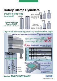
Reduced stroke end impact and noise:New standards to meet consumer demand.Free mounting3 types of mounting orientations can be accommodated depending on the installation conditions.Axial mounting (Tapped hole) Vertical mounting (Body through-hole) Lateral mounting (Body through-hole)Approximately 2.4 times of allowable kinetic energy(Compared to the old <strong>Series</strong> CU with rubber bumper)Improved allowable kinetic energy absorption.Allowable kinetic energy (J)321<strong>Series</strong> CU comparison0.11 0.2820: with air cushion: with rubber bumper0.180.440.2925 32Bore size (mm)Improved repeatability0.70When compared to rubber bumper type actuators, aircushion type cylinders are less likely to be affected bypressure fluctuations, and therefore better able toachieve a stable and smooth stroke.Size VariationsModelC(D)U20C(D)U25C(D)U32Improved sound insulation(Reduced impact noise at the stroke end)• Noise reduction of more than 11dB is possible(compared to <strong>Series</strong> CU20 with rubber bumper).Interchangeable mountingMounting dimensions (J, K, R, and E) are the sameas the rubber bumper type <strong>Series</strong> CU.KStandard strokeRJ20 30 40 50 60 70 80 90 100EEAuto switch• ø20 to ø32Direct mounting styleauto switchCUJCUCQSCQMCQ2RQMUD--X20-Data7-3-49
Free Mount Cylinder with Air Cushion<strong>Series</strong> CUø20, ø25, ø32How to OrderWithout auto switchWith auto switchCU 32CDU 325050AAF9BWBuilt-in magnetBore size20 20 mm25 25 mm32 32 mmNumber of auto switchesNilS2 pcs.1 pc.Auto switchNil Without auto switch∗ For the applicable auto switchmodel, refer to the table below.SymbolNilTNTFThread typeType Bore sizeM thread ø20, ø25RcNPT ø32GAir cushionA With air cushionCylinder stroke (mm)Refer to "Standard Stroke"on page 7-3-51.Applicable Auto Switch/Refer to page 7-9-1 for further infomation on auto switches.TypeReed switchSolid state switchSpecialfunction——Diagnosticindication2-colorindication( )ElectricalentryGrommetGrommetIndicatorlightNoYesYesWiring(output)2-wire3-wire(NPN equiv.)3-wire(NPN)3-wire(PNP)2-wire3-wire(NPN)3-wire(PNP)2-wire5 V 100 V24 V12 V or less12 V 100 V—Load voltageDC5 V5 V12 V12 V24 V5 V12 V12 V∗ Lead wire length symbols: 0.5 m ............. Nil (Example) A933 m ............. L A93L5 m ............. Z F9NWZNote) Solid state switches marked "" are produced upon receipt of order.AC——Auto switch modelPerpendicularA90VA93VA96VM9NVM9PVM9BVF9NWVF9PWVF9BWVIn-lineA90A93A96M9NM9PM9BF9NWF9PWF9BWLead wire length (m) ∗0.5(Nil)3(L)5(Z)———Applicable loadICcircuit—ICcircuitICcircuit—ICcircuit—RelayPLC—RelayPLC7-3-50
Free Mount Cylinder with Air Cushion <strong>Series</strong> CUSpecificationsTypeFluidProof pressureMaximum operating pressureMinimum operating pressureAmbient andfluid temperatureRod end threadRod end thread toleranceStroke length tolerancePiston speedEffective Cushion LengthBore size (mm)Effective cushion length (mm)Standard StrokeBore size (mm)20, 25, 32Pneumatic (Non-lube)Air1.0 MPa0.7 MPa0.08 MPaWithout auto switch: –10°C to 70°C (No freezing)With auto switch: –10°C to 60°C (No freezing)Male threadJIS Class 2206.6+ 1.0050 to 500 mm/s256.7Standard stroke (mm)20, 30, 40, 50, 60, 70, 80, 90, 100∗ Intermediate strokes are also available upon receipt of order. Please contact <strong>SMC</strong>.Minimum stroke length is 20 mm.327.7CUJCUCQSCQMCQ2RQMUD--X20-DataTightening Torque:Bore size(mm)20, 2532Hexagon sockethead cap screwsize (mm)M5M6When mounting <strong>Series</strong> CU referto the table below.Proper tighteningtorque (N◊m)5.10 ±10%8.04 ±10%Allowable Kinetic EnergyRefer to “Selection” on 7-3-56regarding allowable kinetic energy.Theoretical OutputBore size (mm)202532OperatingdirectionOUTINOUTINOUTIN0.394.279.2147124241207OUTOperating pressure (MPa)0.5157132246206402346IN0.7220185344288563454(N)WeightBasic WeightBore size (mm)202532201862894643020832351240230357560Standard stroke (mm)5025239160860274425656702964597048031849375290340527800100362561848(g)Additional WeightBore size (mm)202532Magnet5611(g)7-3-51
<strong>Series</strong> CUConstructionComponent PartsNo.Descriptionq Cylinder tubew Rod cover/Bearinge Head coverr Pistont Piston rody Snap ringu Rod end nuti Cushion needle assemblyo Steel ball!0 Magnet!1 Auto switch!2 Piston gasket!3 Piston seal!4 Rod seal!5 GasketMaterial No. of pcs. NoteAluminum alloyAluminum alloyAluminum alloyAluminum alloyStainless steelCarbon tool steelCarbon steel—Carbon steelMagnetic material1111111(2)21Hard anodizedHard anodizedClear chromatedChromatedPhosphate coatedNickel platedA—(2) D- M9 typeNBRNBRNBRNBR1211Replacement Parts: Seal KitBore size (mm)202532Kit no.CU20A-PSCU25A-PSCU32A-PSContents!3, !4, and !57-3-52
Free Mount Cylinder with Air Cushion <strong>Series</strong> CUDimensions2-cushion needle2-øP through2-portQCUJRCUEGAGBCQSCQM4-NNCQ2MMRQCBøDMUKCJD-CAJA-XKABWidth across flats LAA'HE2-øP through4-øT counterboreS + StrokeZ + Stroke20-DataBore size(mm)202532Port sizeM5 x 0.8M5 x 0.8Rc 1/8A1215.519.5A'141822B263240C425062CA202531CB222531D81012E91011GA2932.535GB2722.525H192327J162024JA121519Bore size(mm)KKALMMNNPQRTSZStandard stroke202532303848567568M6 x 1.0M8 x 1.25M10 x 1.25M5 x 0.8 with depth 8M5 x 0.8 with depth 8M6 x 1.0 with depth 95.55.56.61323.5291620249.3 with depth 89.3 with depth 911 with depth 11.55351.5567274.58320, 30, 40, 50, 60,70, 80, 90, 1007-3-53
<strong>Series</strong> CUProper Auto Switch Mounting Position (Detection at stroke end) and Its HeightD-A9D-M9D-F9WA22 (24.5)2.80.5WBThe dimension in ( ) is for D-A93 type.D-A9VD-M9VD-F9WVA22 (20)5 (7)WBThe dimension in ( ) is for D-M9V and D-F9WV.Bore size D-A9, D-A9V D-M9, D-F9W D-M9V, D-F9WV(mm)202532A182022.5B151113.5W13 (10.5)9 (6.5)11.5 (9)A2224.526.5B191517.5W957.5A2224.526.5B191517.5W1179.5∗ Values in ( ) are dimensions for D-A93 type.Operating RangeSwitch modelD-A9, D-A9VD-M9, D-M9VD-F9W, D-F9WVBore size (mm)20 25 321156.512.5571457∗ Values in this table include hysteresis and are to be used asa guide only. They do not guarantee an actual fixed range(expect approximately ±30% dispersion). Values may varygreatly depending on the operating environment.7-3-54
Free Mount Cylinder with Air Cushion <strong>Series</strong> CUAuto Switch Rail Position4-ø4.2B4-3CUJABore size (mm)202532A212735B232527CUCQSCQMCaution on Proximity InstallationCQ2RQWhen free mount cylinders equipped with D-A9 or D-F9 type auto switches are used, be sure to providean extra clearance in addition to what is suggested inthe table at right. If the distance between two cylindersis less than the noted value, auto switches maymalfunction. When for some reason you cannot avoidinstalling cylinders closer than the required clearance,install a steel plate or magnetic shield plate (MU-SO25) on the side of the cylinder facing the autoswitches to shield them. (Please contact <strong>SMC</strong> fordetails.) Auto switches may malfunction if a shieldingplate is not used.PitchBore size (mm)202532Mounting pitch (mm)404656MUD--X20-Data7-3-55
<strong>Series</strong> CUSpecific Product PrecautionsBe sure to read before handling.Installation and Removal of Snap RingsCaution1. Use appropriate pliers (Type C snap ring installingtool) for installation and removal of snap rings.2. Even when using appropriate pliers (Type C snapring installing tool), proceed with caution as there isa danger of the snap ring flying off the end of thepliers (tool) and causing bodily injury or damage tonearby equipment. After installation, make sure thatthe snap ring is securely seated into the snap ringgroove before supplying air.1. Refer to the below table for mounting cylinders.Tightening TorqueBore sizes(mm)20, 2532CautionSelection1. Operate the cylinder to the stroke end.When the stroke is restricted by an external stopper or aclamped workpiece, sufficient cushioning and noise reductionmay not be achieved.2. Strictly observe the limiting ranges for load weightand maximum speed (Graph (1)). Also, the limitingranges provided here are based on the conditionthat the cylinder is operated to the stroke end with aproper cushion needle adjustment.If operated beyond the limiting ranges, excessive impact willoccur and this may cause damage to equipment.Graph (1)Caution25.00MountingHexagon socket head cap screw(mm)M5M6Proper tightening torque(N⋅m)5.10 ±10%8.04 ±10%: Operating pressure 0.5 MPa: Operating pressure 0.4 MPaCautionSelection3. Adjust the cushion needle to reduce excessivekinetic energy from the piston impact at the strokeend by allowing it to absorb sufficient kineticenergy during the cushion stroke.If due to improper adjustment, the piston impacts the strokeend with excessive kinetic energy (values above those given inTable (1)), an excessive impact will occur and this may causedamage to equipment.Table (1) Allowable Kinetic Energy at Piston Impact2025Piston speed50 to 500 mm/sAllowable kinetic energy 0.0550.094. Strictly observe the limiting ranges for the piston rodlateral load (Graph (2)).If operated beyond the limiting ranges, equipment life may bereduced or damage to equipment may occur.Piston Rod Lateral Load (Graph (2))Lateral load (N)5.004.504.003.503.002.502.001.501.000.500.00CautionCushion Needle Adjustment1. Keep the adjustment range for the cushion needlebetween the fully closed position and the rotationsshown below.ø20ø32ø25320.1520 30 40 50 60 70 80 90 100Stroke (mm)(J)20.00ø20 to ø32Rotations2.5 rotations or lessLoad weight (kg)15.0010.005.00ø32ø25ø20Use a 3 mm flat head watchmakers’ screwdriver to adjust thecushion needle. The adjustment range for the cushion needlemust be between the fully closed position and the open positionranges indicated in the above table. A retaining mechanismprevents the cushion needle from slipping out; however, it mayspring out during operation if it is rotated beyond the rangesshown above.0.0010 100 1000Maximum speed (mm/s)7-3-56
Low Speed CylinderDouble Acting, Single Rod<strong>Series</strong> <strong>CUX</strong>ø10, ø16, ø20, ø25, ø32The external dimensions and the related things about autoswitches are the same as standard type, double acting, singlerod. For <strong>Series</strong> CU, CDU, refer to Best <strong>Pneumatics</strong> Vol. 7.How to OrderWithout auto switch<strong>CUX</strong>1030DWith auto switchCDUX1030DF9BWBuilt-in magnetNumber of auto switchesNilS2 pcs.1 pc.Low speed cylinder1016202532Bore size10 mm16 mm20 mm25 mm32 mmAuto switchNil Without auto switch∗ For the applicable auto switch model, refer tothe table below.∗ Auto switches are shipped together,(but not assembled).ActionD Double acting10, 1620, 25, 32Standard stroke (mm)5, 10, 15, 20, 25, 305, 10, 15, 20, 25, 30, 40, 50Applicable Auto Switch/Refer to page 10-20-1 for further information on auto switches.TypeReedswitchSolid stateswitchSpecial function——Diagnostic indication(2-color indication)∗ Lead wire length symbols:ElectricalentryGrommetGrommetIndicator lightYesYes0.5 m··········Nil3 m·········· L5 m·········· ZLoad voltageLead wire length (m)WiringAuto switch model(Output)0.5 3 5Pre-wireDC AC(Nil) (L) (Z)connectorPerpendicular In-lineApplicable load3-wire(NPN equivalent)2-wire—24 V5 V12 V—100 VA96VA93VA96A93————IC circuit——Relay, PLC3-wire (NPN)M9NV M9N 5 V, 12 V3-wire (PNP)M9PV M9P IC circuit2-wire12 V 24 V—M9BV M9B– Relay, PLC3-wire (NPN)F9NWV F9NW 5 V, 12 VIC circuit3-wire (PNP)F9PWV F9PW 2-wire12 VF9BWV F9BW —(Example) A93∗ Solid state switches marked with “” are produced upon receipt of order.(Example) A93L(Example) F9NWZ• Since there are other applicable auto switches than listed, refer to Best <strong>Pneumatics</strong> Vol. 7 for details.• For details about auto switches with pre-wire connector, refer to page 10-20-66.10-3-8
Low Speed CylinderDouble Acting, Single Rod<strong>Series</strong> <strong>CUX</strong>JIS SymbolDouble acting,Single rodSpecificationsFluidProof pressureMaximum operating pressureAmbient and fluid temperatureLubricationPiston speedCushionRod end threadThread toleranceStroke length toleranceMountingMinimum Operating PressureBore size (mm)Min. operating pressure (MPa)Standard StrokeCautionMounting1. Tightening the cylinder beyond the rangeof the indicated torque (shown in thetable below) may affect operation. ApplyLoctite ® (no. 242, Blue) to the mountingthreads.Bore size(mm)101620, 2532Hexagon sockethead (mm)M3M4M5M6Operating PrecautionsWarningBore size (mm)10, 1620, 25, 32100.06Proper tightening torque(N·m) (Cylinder body)0.54 ±10%1.23 ±10%2.55 ±10%4.02 ±10%1. It might not be able to control <strong>CUX</strong>10 bymeter-out at a low speed operation.Caution1. For <strong>Series</strong> <strong>CUX</strong>10, up to 0.1 Nl/min(ANR) of internal leakage is anticipateddue to cylinder structure.160.06Air1.05 MPa0.7 MPaWithout auto switch: –10 to 70°C (No freezing)With auto switch: –10 to 60°C (No freezing)Not required (Non-lube)ø10, ø16: 1 to 300 mm/sø20 to ø32: 0.5 to 300 mm/sRubber bumper on both endsMale threadJIS Class 2Maintenance1. Replacement parts/Seal kitOrder it in accordance with the bore size.Bore size(mm)16202532200.05Precautions+1.00Basic styleStandard stroke (mm)5, 10, 15, 20, 25, 305, 10, 15, 20, 25, 30, 40, 50CautionKit no.Note)250.05Note) Tolerance +1.00320.05Be sure to read before handling. For Safety Instructions and ActuatorPrecautions, refer to pages 10-24-3 to 10-24-6.Contents<strong>CUX</strong>16-PS Piston seal: 1 pc.<strong>CUX</strong>20-PS Rod seal: 1 pc.<strong>CUX</strong>25-PS Gasket: 1 pc.<strong>CUX</strong>32-PS Grease pack (10 g): 1 pc.∗ It is impossible to replace seals in boresize 10 mm.2. Grease packWhen maintenance requires only grease,use the following part numbers to order.Grease packGR-L-005 (5 g)GR-L-010 (10 g)GR-L-150 (150 g)RE A BRECCXCYMQ Q MRHCMK(2)RS Q GRS AHRZQMI W SCEP1CE1CE2ML2BC G5-SJCVMVGQCCRBJD--X20-Data10-3-9
Mini-free Mount Cylinder<strong>Series</strong> CUJø4, ø6, ø8, ø10CUJCUCQSCQMCQ2RQMUD--X20-Data7-2-1
Mini-free Mount CylinderMiniature Bodyø41013 + Stroke17CUJB4-4D15ø6CDUJB6-8D1913 18 + Stroke26ø8CDUJB8-15D2113 18 + Stroke33ø10CDUJB10-20D2213.5 18 + Stroke38CUJCU Length is shortened by approx. 64% max. Volume is reduced by approx. 70% max.(As compared with <strong>SMC</strong> <strong>Series</strong> CU cylinders without magnet)Dimensions (Without magnet)AaC + StrokebBc + StrokeBore size(mm)46810A(a) B(b) C(c)10(—)13(13)13(—)13.5(15)15(—)19(22)21(—)22(24)13(—)13(33)13(—)13(36)Numbers in parentheses are the dimensions of <strong>SMC</strong> <strong>Series</strong> CU cylinders.7-2-2
<strong>Series</strong> CUJ ø4, ø6, ø8, ø10Concentrates wiring and pipingon one sideAllows more efficient installation, since four directionscan be used freely.FreeFreeFree mount design allowsinstallation from fourdirections.Short pitch mountingis possible.CUJFreeFreeEPitch Dimensions(Without magnet)Bore (mm)46810E10131313.5CUCQSCQMCQ2RQMUD-Easy seal replacementSeals can be replaced easily just byremoving the rod cover.Rod coverWith boss in rod side (h9)Centering can be done easily.Tolerance h9-X20-DataTwo auto switchescan be installed evenfor 4 mm strokes.Compliant for clean roomClean <strong>Series</strong>10-11-<strong>Series</strong> CUJSolid state switchD-F8<strong>Series</strong> Variations<strong>Series</strong>CUJBore size(mm)46810ActionDouble actingSingle acting, Spring returnDouble actingSingle acting, Spring returnDouble actingSingle acting, Spring returnDouble actingSingle acting, Spring returnStroke (mm)4 6 8 10 15 20 CleanseriesAuto switchNoneSolid stateswitchD-F8D-M9Rod endconfigurationMale threadWithout threadFemale threadMale thread7-2-3
Mini-free Mount Cylinder<strong>Series</strong> CUJø4, ø6, ø8, ø10How to Order46810Bore size4 mm6 mm8 mm10 mmWithout auto switchCUJ B6 10 DWith auto switchCDUJ B 610DF8NSBuilt-in magnetBMounting styleBasic style (Through type)6810Bore size6 mm8 mm10 mmCylinder stroke (mm)∗ Refer to “Standard Stroke” on the following page.ActionNilMDSDouble actingSingle acting, Spring returnRod end threadRod end female thread (Without thread for ø4)Rod end male threadNumber of auto switchesNil 2 pcs.S 1 pc.∗ M9 includes one auto switch.Auto switchNil Without auto switch (Built-in magnet)∗ For the applicable auto switch model, refer to thetable below.∗ Auto switches are shipped together, (but notassembled).Applicable Auto Switch/Refer to page 7-9-1 for further information on auto switches.TypeSolid stateswitchSpecial function—ElectricalentryGrommetIndicatorlightYesWiring(Output)3-wire (NPN)3-wire (PNP)2-wire∗ Lead wire length symbols: 0.5 m··········Nil (Example) F8N3 m·········· L (Example) F8NL24 VLoad voltage Auto switch model Lead wire length (m) ∗Electrical entry direction 0.5 3 5Pre-wireDC ACPerpendicular In-line (Nil) (L) (Z)connector— M9N F8N — —12 V— M9P —F8P — ——— M9B F8B — —∗ Auto switches marked with “” are produced upon receipt of order.Applicable loadRelay,PLC7-2-4
Mini-free Mount Cylinder <strong>Series</strong> CUJSpecificationsJIS SymbolDouble acting,Single rod typeSingle acting,Spring returnStandard StrokeActionDouble actingSingle acting,Spring returnBore size (mm)468, 10468, 10Standard stroke (mm)4, 6, 8, 104, 6, 8, 10, 154, 6, 8, 10, 15, 204, 64, 6, 84, 6, 8, 10Bore size (mm)ActionFluidProof pressureMinimum operating Double actingpressureSingle acting, Spring returnMaximum operating pressureAmbient and fluid temperatureCushionLubricationPiston speedThread toleranceStroke length toleranceMountingTheoretical Output/Double ActingBore size(mm)46810Rod size(mm)OperatingdirectionOUTINOUTINOUTINOUTINSpring Reaction Force/Single ActingSpring in pre-loaded condition INBore size(mm)46810Weight/Double Acting2456When the spring is set in the cylinderSpringconditionPre-loadedLoadedPre-loadedLoadedPre-loadedLoadedPre-loadedLoadedPiston area(mm 2 )12.69.428.315.750.330.678.550.341.702.552.453.334.676.475.046.774 6 8 10Double acting/Single acting, Spring returnAir1.05 MPa0.35 MPa0.15 MPa0.3 MPa0.1 MPa0.2 MPa0.7 MPaWithout auto switch: –10 to 70°C (No freezing)With auto switch: –10 to 60°C (No freezing)NoneNon-lube50 to 500 mm/sJIS Class 261.272.552.013.333.766.474.186.77Operating pressure (MPa)0.33.762.828.484.7115.079.1823.5615.07Through-holeOUTStroke (mm)+0.508——1.573.332.866.473.316.770.56.284.7114.137.8525.1315.3139.2625.13Spring in loaded conditionOUTINWhen the spring is contracted by applying air0.78.796.5919.7910.9935.1821.4454.9735.1810————1.966.472.456.77(N)(N)CUJCUCQSCQMCQ2RQMUD--X20-DataBore size(mm)CUJB4CUJB6CUJB8CUJB104 67.212.415.617.97.913.617.019.4Weight/Single ActingStandard stroke (mm)8 108.6 9.314.8 16.018.4 19.720.8 22.315—18.923.025.920——26.429.5(g)Additional weightWith magnet Rod end male thread—0.42.70.83.01.53.22.6Bore size(mm)CUJB4CUJB6CUJB8CUJB10Standard stroke (mm)4 6 8 107.212.815.817.97.914.017.219.4—15.218.620.8——19.922.3(g)Additional weightWith magnet Rod end male thread—0.42.40.82.51.52.42.67-2-5
<strong>Series</strong> CUJMountingThrough-hole mounting bolts are available for mounting a cylinder.Ordering: Add the word “CUJ-” in front of the bolts to be used.(Example) CUJ-M3 x 27lBA A CBDAxial mounting styleLateral mounting styleWithout Auto Switch For Axial MountingModelCUJB4-4-6-8-10CUJB6-4-6-8-10-15CUJB8-4-6-8-10-15-20CUJB10-4-6-8-10-15-20A4555B212325272224262833222426283338222426283338Mounting boltM2.5 x 21lM2.5 x 23lM2.5 x 25lM2.5 x 27lM3 x 22lM3 x 24lM3 x 26lM3 x 28lM3 x 33lM3 x 22lM3 x 24lM3 x 26lM3 x 28lM3 x 33lM3 x 38lM3 x 22lM3 x 24lM3 x 26lM3 x 28lM3 x 33lM3 x 38lFor Lateral MountingModelCUJB4-4-6-8-10CUJB6-4-6-8-10-15CUJB8-4-6-8-10-15-20CUJB10-4-6-8-10-15-20C4555D14181818Mounting boltM2.5 x 14lM3 x 18lM3 x 18lM3 x 18lWith Auto Switch For Axial MountingModelCDUJB6-4-6-8-10-15CDUJB8-4-6-8-10-15-20CDUJB10-4-6-8-10-15-20A555B2729313338272931333843272931333843Mounting boltM3 x 27lM3 x 29lM3 x 31lM3 x 33lM3 x 38lM3 x 27lM3 x 29lM3 x 31lM3 x 33lM3 x 38lM3 x 43lM3 x 27lM3 x 29lM3 x 31lM3 x 33lM3 x 38lM3 x 43lFor Lateral MountingModelCDUJB6-4-6-8-10-15CDUJB8-4-6-8-10-15-20CDUJB10-4-6-8-10-15-20C555D181818Mounting boltM3 x 18lM3 x 18lM3 x 18l7-2-6
Clean <strong>Series</strong>10 C D UJB 6How to OrderMini-free Mount Cylinder <strong>Series</strong> CUJDouble acting8 D F8NClean <strong>Series</strong>10 Relief type11 Vacuum suction typeSpecificationsBuilt-in magnetNil NoneD Yes (Built-in)6810Bore size6 mm8 mm10 mmThe specifications are the same as those for the standarddouble acting type. Refer to page 7-2-5.Nil Without auto switch (Built-in magnet)∗ Applicable auto switch models are the sameas those for the standard, double acting type.Refer to page 7-2-5.Rod end male threadNilMDimensionsAuto switchRod end female threadRod end male threadStrokeThe specifications are the same as those forthe standard double acting type.Refer to “Standard Stroke” on page 7-2-5.M3 x 0.5(Relief port: 10—See above)(Vacuum port: 11—See above)Number of auto switchesNil 2 pcs.S 1 pc.11 3.53.52-M3 x 0.5(Port size)CUJCUCQSCQMCQ2RQMUD--X20-Data3C + StrokeB + StrokeA + StrokeBore size(mm)6, 8, 10Without auto switchWith auto switchA B C A B C24 18 11.5 29 23 16.57-2-7
<strong>Series</strong> CUJConstructionDouble acting!2!3 w e q !1 r y o etSingle actingWithout magnetBuilt-in magnetø4w i e u u i r y o e !0Without magnetBuilt-in magnetRod end male threadComponent PartsReplacement Parts: Seal Kit (For double acting)No.qwertyuio!0!1!2!3DescriptionCylinder tubeRod coverWithout switchPistonWith switchPiston rodSeal retainerMagnet retainerReturn springBronze elementMagnetRod end nutPiston sealRod sealTube gasketMaterialAluminum alloyCopper alloyStainless steelAluminum alloyStainless steelStainless steelAluminum alloyPiano wireSintered metallic BC—SteelNBRNBRNBRNoteHard anodizedElectroless nickel platedChromatedCUJB4 onlyChromatedNickel platedBore size (mm)46810Kit no.CUJB4-PSCUJB6-PSCUJB8-PSCUJB10-PSContentsSet of nos. above !1, !2, !3and an exclusive grease pack.Replacement Parts: Seal Kit (For single acting)Bore size (mm)46810Kit no.CUJB4-S-PSCUJB6-S-PSCUJB8-S-PSCUJB10-S-PSContentsSet of nos. above !1and an exclusive grease pack.7-2-8
Dimensions for ø4 Double Acting/Single ActingMini-free Mount Cylinder <strong>Series</strong> CUJWithout magnet: CUJB4Note) The angular position of the width across flats is not fixed with respect to the tube.2-M3 x 0.5(Port size)6 3.5ElementCUJWidth across flats 5CU7.5CQS57.515ø6h9ø2510Single actingRod end male threadWidth across flats 4M2 x 0.4M2 x 0.44.6ø25CQMCQ22-ø2.8 through2.532.57.5 + Stroke 2-ø2.8 through13 + Stroke18.5 + StrokeRQMUD--X20-Data1.6641.672.512.5Rod end nut part no. : NTJ-0047-2-9
<strong>Series</strong> CUJDimensions for ø6 Double Acting/Single ActingWithout magnet: CUJB6Note) The angular position of the width across flats is not fixed with respect to the tube.2-M3 x 0.5(Bore size)M2.5 x 0.45 effective depth 53Width across flats 86 3.5ElementWidth across flats 3.52-ø3.3 through7132-ø3.3 throughSingle actingElementSingle actingRod end male threadWidth across flats 3.5Width across flats 5.5M3 x 0.5M3 x 0.5ø9h9ø46.4710719ø9h9ø492.53336.5 + Stroke13 + Stroke19 + StrokeBuilt-in magnet: CDUJB6[Auto switch][5.3][≅ 24]311.5 + Stroke18 + Stroke24 + Stroke2.45.56.52.55.52.412.5Rod end nut part no.: NTJ-006A7-2-10
Dimensions for ø8 Double Acting/Single ActingWithout magnet: CUJB8Mini-free Mount Cylinder <strong>Series</strong> CUJNote) The angular position of the width across flats is not fixed with respect to the tube.M3 x 0.5 effective depth 63Width across flats 10Width across flats 4.52-M3 x 0.5(Port size)6 3.5ElementCUJCU8101121ø11h9ø58CQSCQM2-ø3.3 through7132.5332-ø3.3 throughSingle actingBuilt-in magnet: CDUJB8ElementSingle actingRod end male threadWidth across flats 4.5Width across flats 7M4 x 0.7M4 x 0.7ø11h9ø58.136.5 + Stroke13 + Stroke19 + StrokeCQ2RQMUD-[Auto switch][5.3]-X20-Data[≅ 25]311.5 + Stroke18 + Stroke24 + Stroke3.278.5 2.514.573.2Rod end nut part no.: NTJ-010A7-2-11
<strong>Series</strong> CUJDimensions for ø10 Double Acting/Single ActingWithout magnet: CUJB10Note) The angular position of the width across flats is not fixed with respect to the tube.M3 x 0.5 effective depth 63.2Width across flats 11Width across flats 52-M3 x 0.5(Port size)6 3.5Element2-ø3.3 through713.52-ø3.3 throughSingle actingElementSingle actingRod end male threadWidth across flats 5Width across flats 8M5 x 0.8M5 x 0.8ø12h9ø69.28.511.52210.5ø12h9ø68.52.53 336.5 + Stroke13 + Stroke19 + StrokeBuilt-in magnet: CDUJB10[Auto switch][5.6][≅ 25.5]311.5 + Stroke18 + Stroke24 + Stroke4910.516.52.5Rod end nut part no.: NTJ-015A847-2-12
Mini-free Mount Cylinder <strong>Series</strong> CUJProper Auto Switch Mounting Position (Detection at stroke end) (ø6, ø8, ø10 common)D-F8N/F8P/F8BD-M9N/M9P/M9B• When detecting extended stroke end• When detecting retracted stroke end10 mmor more1 1 3(2)7 – Stroke 3 + Stroke 710 mmor moreCUJCUMounting of Auto SwitchWatchmakers’ screwdriverSet screw• When tightening an auto switch mountingscrew, use a watchmakers’ screwdriver with ahandle of approximately 5 to 6 mm indiameter.Note 1) Solid state switch: D-M9 includes one auto switch.Note 2) To prevent interference caused by the lead wire, provide a clearance of 10 mm ormore in addition to the dimensions stated above.Operating RangeAuto switch modelD-F8D-M9622Applicable bore size (mm)8102.52.52 2CQSCQMCQ2RQMUD--X20-Data• Use a tightening torque of approximately 0.10to 0.20 N·m.Caution on Proximity Installation1. When cylinders with auto switches are adjacent to one anotheras shown in the figure below, provide at least the amount ofspace shown in the tables below between them.If the space is not sufficient, the magnets in adjacent cylinders maycause auto switches to malfunction.Cylinder AAuto switchCylinder B2. In the case of bore size ø6 cylinders with auto switches, keepthe switch groove side surface at least 2.5 mm away from amagnetic substance.If a magnetic substance is getting closer within 2.5 mm, autoswitches may malfunction due to a drop in magnetic force.∗ If this surface is to be used for mounting, a spacer composed of anon-magnetic substance (aluminum, etc.) is required as shown inthe figure below.CUJ cylinderAuto switchNon-magnetic spacer of 2.5 mm or moreMagneticsubstancedL∗ The space can be reduced byattaching shielding plates (steelplates 0.2 to 0.3 mm thick) to thesides of the cylinders facingeach other. In the case of boresize ø6, be sure to attach a plateon Cylinder A (on the surfaceopposite to the switch groove).Without Shielding PlateBore (mm)LdBore (mm)Ld619661638196With Shielding Plate813.50.51019.5610140.57-2-13
<strong>Series</strong> CUJSpecific Product Precautions 1Be sure to read before handling.CautionCUJB4C(D)UJB6C(D)UJB8C(D)UJB10BoltM2.5 x 0.45M3 x 0.5MountingWhen mounting a mini-free mount cylinder, tighten the boltswith the proper tightening torque.Proper tightening torque (N·m)0.541.06With Auto SwitchSelectionStrictly observe the limiting range of lateral load on a piston rod.(Refer to the graphs below.) If this product is used beyond thelimits, it may shorten the machine life or cause damage.0.50.4ø10Without Auto Switch0.4ø10Tightening torqueTightening torqueAllowable lateral load W (N)0.30.2ø8ø6Allowable lateral load W (N)0.30.2ø8ø60.10.1 ø4CautionBore size (mm)Piston speed (m/s)Allowable kinetic energy (J)Allowable Kinetic EnergyWhen driving an inertial load, operate a cylinder with kineticenergy within the allowable value. The range in the chart belowthat is delineated by bold solid lines indicates the relationbetween load weights and maximum driving speeds.43.8 x 10 –3 60.056.25 x 10 –3 8to 0.59.35 x 10 –3 1012.5 x 10 –30 4 6 8 10 15 20Stroke ST (mm)0 4 6 8 10 15 20Stroke ST (mm)10Load weight (kg)10.1ø10ø8ø6ø40.010.01 0.1 1.0Maximum speed V (m/s)7-2-14
<strong>Series</strong> CUJSpecific Product Precautions 2Be sure to read before handling.CautionSince the cylinder port size of M3 x 0.5 is used, use thecylinder series models listed below when connecting speedcontrollers and fittings directly to cylinders.1. After manually tightening speed controllers and fittings, tightenapproximately a quarter turn more using a tightening tool. Incases where there are gaskets in two places such as universalelbows, universal tees, etc., double the additional tightening toa half turn. If screws are tightened excessively, air leakagemay result due to broken threads or a deformed gasket. Ifscrews are tightened insufficiently, looseness andaccompanying air leakage are likely to occur.With Auto SwitchBore size (mm)6, 8, 10Port sizeM3 x 0.5Stroke (mm)4 or moreAS121F-M3-23AS121F-M3-04AS131F-M3-23AS131F-M3-04∗ Only applicable to the mounting position shown in Fig. (1) below.Without Auto SwitchBore size (mm)Port sizeStroke (mm)AS121F-M3-23AS121F-M3-04AS131F-M3-23AS131F-M3-04Fig. (1)Mounting of Speed Controllers and FittingsWith Auto Switch6——4, 6, 8, 10M3 x 0.58 or more∗ Only applicable to the mounting position shown in Fig. (1) below.Bore size (mm)Port sizeStroke (mm)One-touch fitting KJS23-M3M-3AUHose nippleM-3ALUWithout Auto SwitchBore size (mm)Port sizeStroke (mm)One-touchfittingHose nippleKJS23-M3KJS04-M3KJH23-M3KJH04-M3KJL23-M3KJL04-M3KJW23-M3KJW04-M3M-3AUM-3ALU4———————4 : Applicable to mounting positions 1, 2, 3 and 4. : Applicable to mounting positions 1, 2 and 3. : Applicable to mounting positions 1 and 3.6, 8, 10M3 x 0.56 or more4 6, 8, 10M3 x 0.56 or more4———————6 or moreCUJCUCQSCQMCQ2RQMUD--X20-DataMounting condition 1 Mounting condition 2a) Side mounting b) Rod side mountingMounting condition 3 Mounting condition 4∗ The above figures show the mounting positions with series KJS One-touchfittings installed.∗∗ Refer to the sections starting “Best <strong>Pneumatics</strong> Vol. 15” for the details ofOne-touch fittings and hose nipples.7-2-15
Free Mount Cylinder for Vacuum<strong>Series</strong> ZCUKZXZRA free mount cylinder with a vacuum passage inthe rod to meet the requirements forAir cylinder + Vacuum pad .A vacuum passage has been provided in the rod of the CUK cylinder to enable avacuum pad to be installed on the end of the rod.ZMZHZUZLZYZQZFNot necessary to provide vacuum tubing space atthe end of the rod.The area around the vacuum pad is uncluttered.ZPZCUAMJMisc.Non-rotationg rodA guide is provided as standardequipment Non-rotating Rod Accuracy(no load: when the rod isretracted on the detent plate side):ø10, ø16 ±0.8°ø20, ø25, ø32 ±0.5°Do not apply a lateral load to thepiston rod. Because the piston rodis a hollow rod, a lateral load cancause the piston rod to bend or break.Vacuum pad (Pad diameter: ø2 to ø50)Auto switchReed switch:D-A9 (Heavy-duty cord, in-line entry)D-A9V (Heavy-duty cord, perpendicular entry)Solid state switch:D-M9, D-F9W (Heavy-duty cord, in-line entry)D-M9V, D-F9WV (Heavy-duty cord, perpendicular entry)How to provide piping to thevacuum sideCap pipingThe piston rod of the vacuum side does not protrude.Also, the vacuum outlet tube does not move whenthe piston is operating.Vacuum port pressure range: –101 kPa to 0.6 MPaPressurize only when releasing the vacuum. At thattime, use it under the cylinder operating pressure.Rod pipingLighter weight than the cap piping.Can also be used for air blowing.Vacuum port pressure range: –101 kPa to 0.6 MPa13-12-1
Without autoswitch ZCUK C 16With auto switchBuilt-in magnet20DZCDUK C 16 20 D F9BWStyle (Tubing method in vacuum side)/(Rod end shape)Bore sizeC Cap piping/Male threadD Cap piping/Male thread10 10 mmQ Rod piping/Male thread16 16 mmR Rod piping/Pad direct mounting20 20 mm25 25 mm32 32 mmApplicable Auto Switch/Indicator lightHow to OrderSNumber of auto switchesNil 2 pcs.S 1 pc.Auto switchNil Without auto switch∗ For the applicable auto switch model, refer to the table below.∗ Auto switches are shipped together, (but not assembled).ActingD Double actingRefer to Best <strong>Pneumatics</strong> Vol. 11/12 for further infomation on auto switches.TypeLoad voltagelead wire lengthAuto switch model(m)Special Electrical WiringPrewirefunction entry (output)0.5 3 5DC ACconnectorPerpendicular In-line (Nil) (L) (Z)Applicable load2-wire3-wireReed switchGrommet Yes (NPN)—24 V5 V12 V—100 VA96VA93VA96A93————IC——Relay, PLC3-wire (PNP)M9NV M9N5 V,12 V3-wire (PNP) M9PV M9PIC2-wire —Solid state switchGrommet Yes24 V 12 V M9BV M9B Relay,—Diagnosis3-wire (PNP)F9NWV F9NWPLC5 V,12 VICindication3-wire (PNP) F9PWV F9PW(2 colors)2-wire 12 V F9BWV F9BW—∗ Lead wire length symbols: 0.5 m Nil Ex.) A93 ∗ : Can be manufactured upon receipt of the order.3 m L Ex.) A93L• For details about auto switches with pre-wire connector, refer to Best <strong>Pneumatics</strong>5 m Z Ex.) F9NWZVol. 11/12.How to Order Vacuum PadZPTDia. (mm)02 ø204 ø406 ø608 ø810 ø1013 ø1316 ø1620 ø2025 ø2532 ø3240 ø4050 ø5002 U N B4Female threadVacuum entry (Mounting thread diameter)Symbol Thread dia. ø2 to ø8 ø10 to ø16 ø20 to ø32 ø40, ø50B4 M4 x 0.7— — —B5 M5 x 0.8— —B6B8B10M6 x 1M8 x 1.25M10 x 1.25—————MaterialN NBRS Silicon rubberU Urethane rubberF Fluoro rubberGN Conductive NBR (ø2 to ø16)GS Conductive silicon rubber (ø2 to ø16)Pad typeU FlatC Flat with ribsPad Dia./Pad Type2 4 6 8 10 13 16 20 25 32 40 50FlatFlat with ribs — — — —Deep — — — — — — — —Bellows — —D DeepTable (1)B Bellows Dia. (mm)(Application: Refer to “Table (1)”.) Type13-12-2Free Mount Cylinder for Vacuum<strong>Series</strong> ZCUKNote) Refer to page 13-12-4 for combination of cylinder and pad.Bore size – Stroke (mm)10, 16 5, 10, 15, 20, 25, 3020, 25, 32 5, 10, 15, 20, 25, 30, 40, 50—ZPDia. (mm)02 ø204 ø406 ø608 ø810 ø1013 ø1316 ø1620 ø2025 ø2532 ø3240 ø4050 ø5004 U N X11Pressure gauge positionApplicable cylinderSymbolmodelDX11 ZC(D)UK R10DNil ZC(D)UK R16/32Note) “-X11” Pad: ø2 to ø8diameter and flatstyle only available.MaterialN NBRS Silicon rubberU Urethane rubberF Fluoro rubberGN Conductive NBR(ø2 to ø16)GS Conductive siliconrubber (ø2 to ø16)Pad typeU FlatC Flat with ribsD DeepB Bellows (Except “-X11”)
Free Mount Cylinder for Vacuum <strong>Series</strong> ZCUKTubing system in vacuum sideModelRod end shapeApplicable pad styleCap pipingCap pipingRod pipingRod pipingVacuumVacuumVacuumVacuumCaution1. Do not place your finger in theclearance between the detent plateand the cylinder tube.Never put your finger between the nonrotatingplate and cylinder tube. Yourfinger may be pinched when the pistonrod retracts.If your finger is caught, it could injure yourfinger because the cylinder outputs aconsiderable amount of force.2. Make sure that rotational torque is notapplied to the piston rod. If this isunavoidable, operate the cylinder withinthe allowable rotational torque listed inthe table below.Allowable Rotational TorqueBore size (mm) 10 16 20 25 32Allowable rotational torque0.02 0.04 0.10 0.15 0.20(N·m)3. To secure a workpiece to the end of thepiston rod, tighten the workpiece onto thepiston rod with the piston rod fullyretracted so that torque is not applied tothe piston rod.4. To install a cylinder, tighten it within thetorque values indicated in the tablebelow.Proper Tightening TorqueBore size(mm)ø10ø16ø20, ø25ø32PrecautionsBe sure to read before handling.Refer to pages 13-15-3 to 13-15-4for Safety Instructions andCommon Precautions on theproducts mentioned in thiscatalog, and refer to page 13-1-5for Precautions on every series.Hexagon sockethead bolt diameter(mm)M3M4M5M6Proper tighteningtorque (N·m)1.08 ±10%2.45 ±10%5.10 ±10%8.04 ±10%ZCUKCZCUKDZCUKQZCUKRSpecificationsMale threadPad directmountingMale threadFluidProof pressureMaximum operating pressureVacuum port pressureAmbient and fluid temperatureLubricationPiston speedCushionStroke allowanceThread toleranceRod tip screwMountingApplicable padPad direct mounting<strong>Series</strong>ZPTVacuum<strong>Series</strong>ZPTVacuumRefer to page 13-12-4 for details.(Perpendicular vacuumentry female thread)(With pad single unit lock ring)Air1.05 MPa0.7 MPa–101 kPa to 0.6 MPa(At vacuum release 0 to 0.6 MPa) Note)Without auto-switch: –10 to +70°C (No freezing)With auto-switch: –10 to +60°C (No freezing)Not required50 to 500mm/sRubber bumper at both sides+1.00JIS Class 2With or without (Pad direct mounting)Basic typeRefer to page 13-12-4 for details.Note) For a cap style, supply pressure only when vacuum is released. That pressure shouldbe less than the cylinder pressure.Non-rotating Rod Accuracy(No load/At retraction of the rod at the locking plateside)Bore size (mm) 10Non-rotating rod accuracy±0.8°Minimum Operating Pressure16 20 25±0.5°(MPa)Bore size (mm) 10 16 20 25 32Min. Operating Pressure (MPa) 0.13 0.13 0.11 0.11 0.113213-12-3ZXZRZMZHZUZLZYZQZFZPZCUAMJMisc.
<strong>Series</strong> ZCUKApplicable Auto SwitchRefer to Best <strong>Pneumatics</strong> Vol. 11/12 for moredetailed specifications.MountingModelReed switchPart no.D-A90D-A90VElectrical entryGrommet (In-line)Grommet (Perpendicular)FeaturesWithoutindicator light• With Normally closed (NC = b contact), and solid state switches(D-F9G/F9H type) are also available.Refer to Best <strong>Pneumatics</strong> Vol. 11/12 for details.Standard StrokeApplicable cylinderStroke (mm)Bore size (mm)1016202532Double acting style/Single rod type/Non-rotating rodStroke (mm)5 10 15 20 25 30 40 50— —— —Theoretical Output/Double Acting TypeOperating pressure (MPa)Bore sizeRod dia. Piston area(mm) (mm)(mm 2 ) 0.3 0.51016202532468101266.017226441269119.851.679.212420733861322063460.746.2121185289484(N)1 MPa ≅ 10.2 kgf/cm 2 , 1 N ≅ 0.102 kgfVertical mounting (Body through-hole)Lateral mounting(Body throughhole)Minimum Stroke for Mounting Auto SwitchNumber ofauto switchesD-A9, D-A9VApplicable auto switchD-M9, D-M9VD-F9W, D-F9WV1 pc.2 pcs.51055510• In the case of rod end male threadUse series ZPT pad (vertical vacuum entry/female thread mounting).CylinderBore sizeModel(mm) 210ZCUKC16ZCUKQZCDUKC20 —ZCDUKQ 25 —32 —4 6 8 10 13 16 20 25 32 40 50— — — — — — — —— — — — —— ———————Pad (ZPT02 to 50-B4 to 10)Rod dia. (mm)—————————Switch Groove LocationCylinder/Applicable PadThread dia.M4 x 0.7M5 x 0.8M6 x 1.0M8 x 1.25M10 x 1.25• In the case of pad direct mountingUse series ZP pad (single unit).CylinderBore sizeModel(mm)Pad (ZP02 to 50)Rod dia. (mm)2 4 6 8 10 13 16 20 25 32 40 5010 Note)— — — — — — — —ZCUKD16— — — — — — — —ZCUKR20 — — — —— — — — —ZCDUKDZCDUKR25 — — — — — — —— —32 — — — — — — — — — —UNote) When using “ZC(D)UK R10”, use ZP02 to 08U∗-X11. Pad shape isflat only.Bore size (mm) A B10 10.3 1316 15 1820 21 2325 27 2532 35 2713-12-4
Free Mount Cylinder for Vacuum <strong>Series</strong> ZCDUKProper Auto Switch Mounting Position (Detection at stroke end) and Its Mounting HeightD-A9D-M9D-F9WZX( ): Dimensions for “D-A93”ZRD-A9VD-M9VD-F9WVZMZHZUZLZYBore size(mm)1016202532D-A9, D-A9V D-M9, D-F9W D-M9V, D-F9WVA12.5162022.523.5B34678W–1.5 (1)–2 (0.5)–4 (–1.5)–5.5 (–3)–6.5 (–4)A16.5202426.527.5B7.581011.512.5W2.51.50–1.5–2.5A16.5202426.527.5B7.581011.512.5W0.50–2–3.5–4.5Note 1) Negative figures in the table show dimensions mounted inside cylinderbody.Note 2) In the case of 5 mm stroke or the 10 mm stroke, there are times inwhich the switch will not turn OFF or 2 switches will turn ONsimultaneously due to their movement range. Therefore, set theposition approximately 1 to 4 mm outward from the values given in thetable above. Then, perform an operation inspection to make sure thatthe switches operate normally (if 1 switch is used, make sure that itturns ON and OFF properly; if 2 switches are used, make sure thatboth switches turn ON).Note 3) Figures in ( ) in the table W are D-A93.( ): Dimensions for “D-F9V”, “D-F9WV”ZQZFZPZCUAMJMisc.Operation RangeAuto switch modelBore size (mm)10 16 20 25 32D-A9/A9VD-M9/M9V62.59311412.54145D-F9W/F9WV3.5 5.5 6.5 77∗ Since this is the average value at a normal temperature including hysteresis (tolerance ±30%), it isnot guaranteed.PrecautionsBe sure to read before handling. Refer to pages 13-15-3 to 13-15-4 for SafetyInstructions and Common Precautions on the products mentioned in thiscatalog, and refer to page 13-1-5 for Precautions on every series.13-12-5
<strong>Series</strong> ZCDUKAuto Switch SpecificationsMounting of Auto SwitchWatchmaker's screwdriverSet screwMountingPrecautions on Proximity lnstallationIf the mounting pitch of a free-mount cylinder with D-A9, D-F9 typeauto switch is less than the dimensions indicated in the table below,the auto switch could malfunction. Therefore, make sure to provide agreater clearance. If use under the dimensions indicated below isunavoidable, it is necessary to provide a shield. To do so, affix a steelplate or a magnetic shield plate (MU-S025) to the corresponding positionof the cylinder that is placed near the auto switch. (Pleasecontact <strong>SMC</strong> for further details.)If a shield plate is not used, it could cause the auto switch tomalfunction.• To tighten the auto switch mountingscrews, use a watchmaker’s screwdriverwith a grip diameter of 5 to 6 mm.• Tighten the screws to a torque ofapproximately 0.10 to 0.20 N·m.Bore size (mm)1016202532Mounting pitch (mm)2033404656Mounting screw• Do not install using BU-1 (mountingscrews used exclusively for D-9 modelauto switch).(Failure to observe this precaution couldcause the auto switch to break.)Basic Style/With Auto SwitchModelZC(D)UKCZC(D)UKQBore size(mm)10162025321016202532563(68)103(128)180(214)304(358)514(587)49(54)79(104)145(179)259(313)421(494)Weight( ): Denotes the values with D-A93.Cylinder stroke (mm)10 15 20 25 30 40 5069(79)75(85)81(91)87(97)93(103) — —115(145)127(157)139(169)151(181)163(193) — —204(244)228(267)252(292)276(316)300(340)348(388)396(436)343(402)382(441)421(480)460(519)499(558)577(636)655(714)574(652)634(712)694(772)754(832)814(892)934(1012)1054(1132)53(63)57(67)61(71)65(75)69(79) — —86(116)93(123)100(130)107(137)114(144) — —159(198)173(212)187(226)201(240)215(254)243(282)271(310)279(338)299(358)319(378)339(398)359(418)399(458)439(498)451(529)481(559)511(589)541(619)571(649)631(709)691(769)(g)13-12-6
Free Mount Cylinder for Vacuum <strong>Series</strong> ZCUKConstructionCap piping/Male thread: ZC(D)UKCø10With auto switchPad direct mountingIn the case of ZC(D)UKDAA cross sectionø16 to ø32AA cross sectionPad direct mountingIn the case of ZC(D)UKDComponent PartsNo.qDescriptionCylinder tubingMaterialAluminum alloyweRod cover BCapAluminum bearing alloyAluminum alloyr PistonAluminum alloyt Piston rodStainless steely BushOil impregnated sintered metalu PlateAluminum alloyi Guide rodStainless steelo BushOil impregnated sintered metal!0 Hexagon set screw Carbon steel!1 Hexagon socket head cap screw Carbon steel!2 Hexagon set screw Carbon steelNoteHard anodizedChromatedHard anodizedChromatedNickel platedBlack zinc chromatedBlack zinc chromatedNickel platedComponent PartsWith auto switchNo.!3DescriptionDamperMaterialUrethane!4!5MagnetAuto switchMagnetic material—!6 Jam nutCarbon steel!7 Piston gasketNBR!8∗Piston seal!9∗Rod seal@0∗GasketNBR@1∗Gasket for cap@2 Seal washerRolled steel/NBRNoteNickel platedZXZRZMZHZUZLZYZQZFZPZCUAMJMisc.Replacement Parts: Seal Kit (Cap piping)Part no.ø10ZCU10-PSø16ZCU16-PSBore size/Part no.ø20ZCU20-PSø25ZCU25-PSø32ZCU32-PSSeal kit consist of item !8, !9, @0, @1 contained in one kit, and can be ordered using the order number for each respectivetubing bore size.13-12-7
<strong>Series</strong> ZCUKConstructionRod piping-Male thread: ZC(D)UKQø10With auto switchPad direct mountingIn the case of ZC(D)UKRAA cross-sectionø16 to ø32With auto switchAA cross-sectionPad direct mountingIn the case of ZC(D)UKRComponent PartsNo.qDescriptionCylinder tubingMaterialAluminum alloyweRod cover BRod cover retainer plateAluminum bearing alloyAluminum alloyr PistonAluminum alloyt Piston rodStainless steely BushOil impregnated sintered metalu PlateAluminum alloyi Guide rodStainless steelo BushOil impregnated sintered metal!0 Hexagon set screw Carbon steel!1 Hexagon socket head cap screw Carbon steel!2 Hexagon set screw Carbon steelNoteHard anodizedChromatedHard anodizedChromatedNickel platedBlack zinc chromatedBlack zinc chromatedNickel platedComponent PartsNo.!3DescriptionDamperMaterialUrethane!4!5Magnetauto switchMagnetic material!6 Jam nutCarbon steel!7 Piston gasketNBR!8 SocketCarbon steel!9 Gasket@0∗Piston seal@1∗Rod sealNBR@2∗Gasket@3 Seal washerRolled steel/NBRNoteNickel platedø16 onlyø16 onlyReplacement Parts: Seal Kit (Rod piping)Part no.ø10CUW10-PSø16CUW16-PSBore size/Part no.ø20CUW20-PSø25CUW25-PSø32CUW32-PSSeal kit consist of item @0, @1, @2 contained in one kit, and can be ordered using the order number for each respectivetubing bore size.13-12-8
Free Mount Cylinder for Vacuum <strong>Series</strong> ZCUKVacuum Piping: Cap Piping/Rod End Shape: Male ThreadZC(D)UKC Cylinder bore – Stroke Dø10Seal washer 2-ø3.2 through hole Port size2-M5 x 0.830 + StrokeZXZRM4 x 0.7Vacuum port sizeM5 x 0.8ZMø1.5 through hole2-ø3.2 through hole4-ø6 depth 5 counterboreZHZUZL36 + Stroke77 + 2 x Stroke20 + StrokeZYZQZFø16 to ø322-øP throughPort size2-M5 x 0.8 [ø32: 2-Rc 1/8]ZPZCUSeal washerGC + StrokeVacuum port sizeAMJMisc.ød ThroughWidth acrossflats L2-øP through4-øT counterboreS + StrokeZ + 2 x StrokeSA + StrokeModelPort sizeStroke rangeAir port Vacuum port (mm)A A' B C ød øD E F FK FL FY GA GCZC(D)UKC16 M5 x 0.8 M5 x 0.8 5 to 30 11 12.5 20 32 2 6 7 8 13 17 28 16.5 Note) 31ZC(D)UKC20 M5 x 0.8 Rc 1 8 5 to 50 12 14 26 40 3 8 9 8 16 20 33 19 33.5ZC(D)UKC25 M5 x 0.8 Rc 1 8 5 to 50 15.5 18 32 50 4 10 10 10 20 22 43.5 21.5 34ZC(D)UKC32 Rc 1 8 Rc 1 8 5 to 50 19.5 22 40 62 5 12 11 12 24 29 51.5 23 35ModelHJLMMZC(D)UKC16 26 14 5 M5 x 0.8 4.5 4 2 12 30 (40) 19.5ZC(D)UKC20 29 16 6 M6 x 1.0 5.5 9 4.5 16 36 (46) 21ZC(D)UKC25 33 20 8 M8 x 1.25 5.5 9 4.5 20 40 (50) 21ZC(D)UKC32 42 24 10 M10 x 1.25 6.6 13.5 4.5 24 42 (52) 22( ): In the case of a mounted auto switch. Note) In the case of ZCUKC16-5D: 14.5 mm.øPQQARSSAøT7.6 depth 6.59.3 depth 99.3 depth 811 depth 11.5Y15.519.524.530.5Z75.5 (85.5)86 (96)94 (104)106 (116)13-12-9
<strong>Series</strong> ZCUKVacuum Piping: Cap Piping/Rod End Shape: Pad Direct MountingZC(D)UKD Cylinder bore – Stroke Dø10Pad for ZCUKD10 (ZP02 to 08U∗-X11)2-ø3.2 throughPort size2-M5 x 0.830 + StrokeVacuum port sizeø1.5 Through2-ø3.2 through4-ø6 depth 5 counterbore36 + Stroke77 + 2 x (Stroke)20 + Strokeø16 to ø322-øP throughPort size2-M5 x 0.8 [ø32: 2-Rc 1/8]Use series ZP padCG + StrokeVacuum port sizeød ThroughWidth acrossflats L2-øP through4-øT counterboreS + Stroke SA + StrokeZ + 2 x StrokeModelZC(D)UKD16ZC(D)UKD20ZC(D)UKD25ZC(D)UKD32Port sizeAir port Vacuum portM5 x 0.8 M5 x 0.8M5 x 0.8 Rc 1 8M5 x 0.8 Rc 1 8Rc 1 8 Rc 1 8Stroke range(mm)5 to 305 to 505 to 505 to 50øA56.6811.5A'78910.5B20263240C32405062ød2345øD681012E791011F881012FK13162024FL17202229FY283343.551.5GA16.51921.523Note)GC3133.53435ModelHJLøPQQARSSAøTWYZZC(D)UKD16 26 14 5 4.5 4 2 12 30 (40) 19.5 7.6 depth 6.5ZC(D)UKD20 29 16 6 5.5 9 4.5 16 36 (46) 21 9.3 depth 8ZC(D)UKD25 33 20 8 5.5 9 4.5 20 40 (50) 21 9.3 depth 9ZC(D)UKD32 42 24 10 6.6 13.5 4.5 24 42 (52) 22 11 depth 11.5( ): In the case of a mounted auto switch. Note) In the case of ZCUKD16-5D: 14.5 mm.3.555515.519.524.530.575.5 (85.5)86 (96)94 (104)106 (116)13-12-10
Free Mount Cylinder for Vacuum <strong>Series</strong> ZCUKVacuum Piping: Rod Piping/Rod End Shape: Male ThreadZC(D)UKQ Cylinder bore – Stroke Dø10Seal washer2-ø3.2 through 2-ø3.2 through ø4/ø2.5 Urethane tube (TU0425) orsoft nylon tube (TS0425)ZXZRM4 x 0.7ZMø1.5 through2-ø3.2 through4-ø6 depth 5 counterbore36 + Stroke70 + 2 x Stroke7 + StrokeZHZUZLZYZQZFø16 to ø322-øP throughPort size2-M5 x 0.8 [ø32: 2-Rc 1/8]ZPZCUSeal washerAMJød ThroughthroughWidth acrossflats L2-øP through4-øT counterboreS + StrokeZ + 2 x StrokeHA +StrokeVacuum port sizeSocket (Only ø16)M5 x 0.8Hexagon width across flats 8Misc.ModelZC(D)UKQ16ZC(D)UKQ20ZC(D)UKQ25ZC(D)UKQ32Port sizeAir port Vacuum portM5 x 0.8 M5 x 0.8 (2)M5 x 0.8 M5 x 0.8M5 x 0.8 M5 x 0.8Rc 1 8 Rc 1 8Stroke range(mm)5 to 305 to 505 to 505 to 50A111215.519.5A'12.5141822B20263240C32405062ød2345øD681012E791011F881012FK13162024FL17202229FY283343.551.5GA16.5 (1)1921.523GC1921.52223ModelHHAJLMMøPQQARZC(D)UKQ16 26 5 14 5 M5 x 0.8 4.5 4 2 12 30 (40) 7.5 7.6 depth 6.5 15.5 68.5 (78.5)ZC(D)UKQ20 29 5 16 6 M6 x 1.0 5.5 9 4.5 16 36 (46) 9 9.3 depth 8 19.5 79 (89)ZC(D)UKQ25 33 5 20 8 M8 x 1.25 5.5 9 4.5 20 40 (50) 9 9.3 depth 9 24.5 87 (97)ZC(D)UKQ32 42 5 24 10 M10 x 1.25 6.6 13.5 4.5 24 42 (52) 10 11 depth 11.5 30.5 99 (109)( ): In the case of a mounted auto switch. Note 1) In the case of ZCUKR16-5D: 14.5 mm. Note 2) In the case of socket equipped type.SSAøTYZ13-12-11
<strong>Series</strong> ZCUKVacuum Piping: Rod Piping/Rod End Shape: Pad Direct MountingZC(D)UKR Cylinder boreStroke Dø10Pad for ZCUKD10 (ZP02 to 08U∗-X11)2-ø3.2 throughPort size2-M5 x 0.8Urethane tube (TU0425) orsoft nylon tube (TS0425)ø1.5 through2-ø3.2 through4-ø6 depth 5 counterbore36 + Stroke70 + 2 x Stroke7 + Strokeø16 to ø322-øP throughPort size2-M5 x 0.8 [ø32: 2-Rc 1/8]Use series ZP padød ThroughthroughWidth acrossflats L2-øP through4-øT counterboreS + StrokeZ + 2 x StrokeHA +StrokeVacuum port sizeSocket (Only ø16)M5 x 0.8Hexagon width across flats 8ModelPort sizeAir port Vacuum portZC(D)UKR16ZC(D)UKR20ZC(D)UKR25M5 x 0.8M5 x 0.8M5 x 0.8M5 x 0.8 (2)M5 x 0.8M5 x 0.8ZC(D)UKR32 Rc 1 8 Rc 1 8Stroke range(mm)5 to 305 to 505 to 505 to 50øA56.6811.5A78910.5B20263240C32405062ød2345øD681012E791011F881012FK13162024FL17202229FY283343.551.5GA16.5 (1)1921.523GC1921.52223ModelHHAJLøPQQARSZC(D)UKR16 26 5 14 5 4.5 4 2 12 30 (40) 7.5 7.6 depth 6.5 3.5 15.5 68.5 (78.5)ZC(D)UKR20 29 5 16 6 5.5 9 4.5 16 36 (46) 9 9.3 depth 8 5 19.5 79 (89)ZC(D)UKR25 33 5 20 8 5.5 9 4.5 20 40 (50) 9 9.3 depth 9 5 24.5 87 (97)ZC(D)UKR32 42 5 24 10 6.6 13.5 4.5 24 42 (52) 10 11 depth 11.5 5 30.5 99 (109)( ): In the case of a mounted auto switch. Note 1) In the case of ZCUKR16-5D: 14.5 mm. Note 2) In the case of socket equipped type.SAøTWYZ13-12-12
Free Mount Cylinder for Vacuum <strong>Series</strong> ZCUKRod end shape: Male threadTubing bore: ø10Dimensions of Pad Mounted ModelTubing bore: ø16 to ø50ModelZC(D)UKC10ZC(D)UKQ10ZC(D)UKC16ZC(D)UKQ16ZC(D)UKC20ZC(D)UKQ20ZC(D)UKC25ZC(D)UKQ25ZC(D)UKC32ZC(D)UKQ32Dia.(mm)øDQHQHPøDQHQHPøDQHQHPøDQHQHPøDQHQHP22.619.536.52.619.541.5—————————44.819.536.54.819.541.5—————————6719.536.5719.541.5—————————Flat/Flat with ribs Deep Bellows8 10 13 16 20 25 32 40 50 10 16 25 40 6 8 10 13 16 20 25 32 409 — — — —— — 7 9 — — — —19.5 — — — —— — 20.5 20.5 — — — —36.5 — — — —— — 37.5 37.5 — — — —919.541.5—————————122144122144——————152142152144——————1821.542.51821.544.5Rod end shape: Pad direct mountingModelZC(D)UKD10ZC(D)UKR10ZC(D)UKD16ZC(D)UKR16ZC(D)UKD20ZC(D)UKR20ZC(D)UKD25ZC(D)UKR25ZC(D)UKD32ZC(D)UKR32Tubing bore: ø10Dia.(mm)øDQHQHPøDQHQHPøDQHQHPøDQHQHPøDQHQHP22.610262.61231Note) ZPU-X11: Flat type only.—————————232346232954233264——————282346282954283264——————3523.546.53529.554.53532.564.5—————————433257433567—————————533358533668122445122447——————182546182548————————————282952283560283870—————————4342.567.54345.577.5720.542.5—————————920.542.5—————————122546122548——————Tubing bore: ø16 to ø501527.548.51527.550.5——————182950182952—————————2232.555.52238.563.52241.573.5——————273356273964274274——————343861344469344779—————————4347.572.54350.582.550—————————5351.576.55354.586.5Flat/Flat with ribs Deep Bellows4 6 8 10 13 16 20 25 32 40 50 10 16 25 40 6 8 10 13 16 20 25 32 40 504.8 7 9 — — — — — — — — — — — — — — — — — — — — — —10 10 10 — — — — — — — — — — — — — — — — — — — — — —26 26 26 — — — — — — — — — — — — — — — — — — — — — —4.8 7 9 — — — — — — — — — — — — 7 9 — — — — — — — —12 12 12 — — — — — — — — — — — — 13 13 — — — — — — — —31 31 31 — — — — — — — — — — — — 32 32 — — — — — — — —— — — —— — — —— — — —— — — —— — — —— — — —— — — —— — — —— — — —121233——————151233——————1812.533.5——————— — — — —— — — — —— — — — —231438———281438———3514.538.5———— —— —— —4318.5505319.551121536———181637———— —— —— —— —— —— —282044——————432960.5————————————121637———1518.539.5———182041———— — — — —— — — — —— — — — —— — — — —— — — — —— — — — —2223.547.5———272448———342953———— —— —— —433465.5533869.5Applicablepad modelZPT-B4ZPT-B5ZPT-B6ZPT-B8ZPT-B10Applicablepad modelNote)ZPU-X11ZPZPZPZPZXZRZMZHZUZLZYZQZFZPZCUAMJMisc.Rod end nutAccessory Dimensions (Attached only to a rod end male thread type.)Seal washerCore sheetSealPart no.NTP-010NTJ-015ANT-015ANT-02NT-03Applicable cylinder bore (mm)1016202532dM4 x 0.7M5 x 0.8M6 x 1.0M8 x 1.25M10 x 1.25H2.44556Material: Carbon steelB78101317C8.19.211.515.019.6D6.87.89.812.516.5Part no.WCS4 x 0.7WCS5 x 0.8WCS6 x 1WCS8 x 1WCS10 x 1Applicable cylinder bore (mm)1016202532Material: Core sheet — Rolled steelNBRSeal —t1.21.21.21.61.6D11.512.514.015.518.013-12-13