Vapor Generation Accessory VGAâ77 Operation manual
Vapor Generation Accessory VGAâ77 Operation manual
Vapor Generation Accessory VGAâ77 Operation manual

Create successful ePaper yourself
Turn your PDF publications into a flip-book with our unique Google optimized e-Paper software.
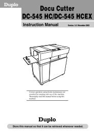
VGA–775. Fit the end of the tube from the pump unit marked ‘Inert gas ‘B’’to the nipple near the bottom of the reagent manifold marked‘Inert gas ‘B’ to separator’. The nipple has a contoured profile.Push the tubing onto the nipple until it covers all of thecontoured section.✒ Note To remove a module and replace it with another, refer to theinstructions in section 3.5.2.2.6 Installing the drain tubingWarningWaste solutions from the VGA-77 may contain concentrated acidswhich can cause severe burns. Your waste vessel must be ofdurable, acid-resistant material. Do not use a glass container. Locatethe vessel where it cannot be knocked over. Empty it frequently.Dispose of waste solutions in accordance with relevant safetypractices.There are two drain outlets located on the underneath side of thereagent module. The outlet closest to the front face of the module isfor tray overflow, the other is to drain liquid from the gas/liquidseparator.'JHVSFÁ. Drain outletsÁDrain tubing should be connected to both of these drain outlets. Toconnect drain tubing to the drain outlet, push the tubing over theoutlet hole so that the wall of the tubing seats firmly into the cavitysurrounding the outlet hole.2-8 Publication date: May 2004