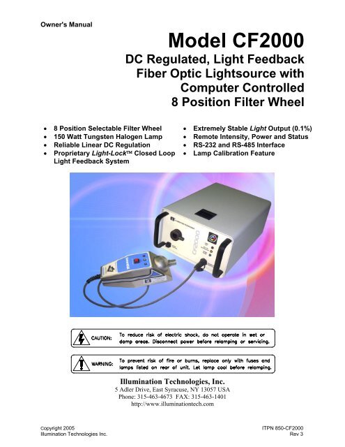
CF2000 Instruction Manual - Illumination Technologies
CF2000 Instruction Manual - Illumination Technologies
CF2000 Instruction Manual - Illumination Technologies
- No tags were found...

Create successful ePaper yourself
Turn your PDF publications into a flip-book with our unique Google optimized e-Paper software.
Illlumination <strong>Technologies</strong>IndexContents <strong>CF2000</strong> SeriesPAGE1] Safety………………………………………………………………………………………………………….22] Description.………………………………………………………………………………………………….33] Power ………………………………………………………………………………………………………….44] Mounting and Clearances………………………………………………………………………………….55] Operation…………………………………………………..………………………………………………….65.1] Set up…..………………………………………………………………………………….65.2] Filter installation…..……………………………………………………………………….75.3] Remote Opertaiton (Communication)………………………………………………….85.4] Start up…………………………………………………………………………………….116] Calibration..……………………………………..…………………………………………………………..137] Technical Data7.1] Lamp Performance……………………………………………………………………….157.2] Lamp Life ……………….………………………………………………………………….167.3] Color Filters……….………………………………………………………………………..178] Service and Trouble Shooting……………………………………………..…………………………..189] Specifications.………………………………………………………………..………………………….2010] Accessories and Service Parts……………………………………………………………………….2111] Warranty……………………………………………………………………………………………..…….22AppendixA] Communiction CablesA.2] RS232…………………..………………………………………………………………..23A.2] RS485…………………..………………………………………………………………..23B] Communication ProtocolB.1] ASCII Programming Protocol……………………………………………………….23B.2] Sample ASCII Programs……………………………………………………………….25C] FILTER SPACERSC.1] Use of Filter Spacers………………………………………………………………….281Copyright 2005 ITPN 850-<strong>CF2000</strong><strong>Illumination</strong> <strong>Technologies</strong> Inc. Rev 3
Safety <strong>Instruction</strong>sCAUTION:• Read all of these instructions before operating the unit.• Follow all warnings and instructions on this piece of equipment• Failure to use this equipment in the manner specified in this manual may cause the protectionfeatures of the unit to be impaired.1. Retain <strong>Instruction</strong>s - All safety and operatinginstructions should be retained for future reference.2. Follow <strong>Instruction</strong>s - All operating and useinstructions should be followed.3. Water and Moisture - The unit should not be usednear water, or in any area where excessive moisturemay come in contact with the unit.Eau Et Moisissure: Le système ne doit pasêtre utilisé prés de l’eau, ou dans unenvironement où la moisissure pourait venir encontact avec le système.4. Mounting - The unit should be mounted horizontallyon a surface or platform, or vertically via fixture only asrecommended by the manufacturer. Never mountwith fiber receptacle pointing down.5. Ventilation - The unit should be positioned such thatits surroundings do not interfere with its properventilation. Ensure that there is adequate air flowbelow (intake) and in the rear (exhaust) of the unit.6. Heat - The unit produces heat and infrared radiation.Do not place flammable materials on or near the unitat any time. Keep unit away from other sources ofheat. The Lamp housing is marked with a HOTSURFACE CAUTION label to prevent accidentalcontact with it before it cools. Always allow time forthe lamp and all surfaces surrounding the bulb to coolbefore attempting to replace lamp.7. Power Source - The unit should be connected to apower source only of the type described in theoperating instructions and as indicated by the powerentry module.8. Grounding - Precautions should be taken to ensurethat proper grounding of the unit is assured.10. Fuse - DO NOT DEFEAT FUSE. Replace only withfuses as described in the operating manual and asmarked on the unit for the operating voltage that theunit is set for.11. Safety Interrupt - DO NOT MANUALLY DEFEATTHE SAFETY INTERRUPT SWITCH.12. Cleaning - The unit should be externally cleanedusing only standard glass type cleaners.Do not use solvents, cleansers orpetroleum distillates. Disconnect powercord before performing any cleaningoperations.13. Liquid and Object Entry - Care should be taken toavoid objects falling into, or liquids being spilled intothe enclosure through openings.14. Nonuse Periods - Disconnect power cord from outletwhen unit will be left unused for a long period.15. Damage Requiring Service - The unit should beserviced by qualified service personnel if it exhibitsany marked change in performance; if the powercord or enclosure has been damaged; or if objects ormoisture have entered the unit.16. Servicing - The user should not service the unitbeyond that described in this manual.All other servicing should be referred toqualified service personnel. Disconnectpower cord before performing anyservice on the unit.17. DB-25 Interface - The user should refer to theOperations section of thismanual for a completedescription of this connectorand the function of each pin.9. Power Cord - Use only the approved power cordsupplied with the unit, or an equivalent IEC 320 powercord with proper certifications. Power cord should berouted such that it will not be pinched, severed orwalked on.2Copyright 2005 ITPN 850-<strong>CF2000</strong><strong>Illumination</strong> <strong>Technologies</strong> Inc. Rev 3
LAMPOUTCALIBRATIONCONNECTOR<strong>CF2000</strong> SeriesDescriptionThe CF 2000 is a DC regulated tungsten halogen light source. It designed optimallylight It fiber accessories. The main features of the unit are the light output is controlled bythe Lightlock TM and light level is set by the 49XX series SmartCal TM calibrator. The lightsource has an internal 8 position filter wheel to allow control of spectral properties. Thecontrol of light intensity and the wheel position are controlled remotely with a digitalinterface.The SmartCal TM calibrators 49XX (sold separately) which set the light level arecalibrated to a NIST traceable reference. The Calibrator and the Lightlock TM featurealong with maintain is set level even through a power cycle. The fiberoptic accessoriesare held in place with a retaining thumb screw.This unit has an IEC 320 power inlet. This outlet will interface with a variety of internationalpower cords and the unit accepts most common AC power. The power switch and fuse boxare located in the power entry module. The remote communication is done through a 25pin “D” connector. See the communication sector of the manual for details.The cover of the light source opens with a slide latch to allow access for control and filterwheel setup, and lamp changes. The unit has lamp status indicators and manual controlson the front panel. See the operation section of the manual for details.OUT OFREGULATIONWHEELHOMEWHEELCONTROL!Fig 1 – <strong>CF2000</strong> Lightsource3Copyright 2005 ITPN 850-<strong>CF2000</strong><strong>Illumination</strong> <strong>Technologies</strong> Inc. Rev 3
<strong>CF2000</strong> SeriesPowerThe power is brought to the unit through the IEC 320 connector at the back of the unit. Therange of the acceptable power is listed in the specification section of the this manual. The powerprotection fuses are located in the module.To service the fuses, start by removing the power cord. Insert a small flat blade screwdriver intoone of the notches near the socket and twits to pop the door open. Pull the door straight out andswing it into the socket (see Figure 1). Lift the fuse holder out of the housing. Only use fuseslisted in the specification section. The fuses should be placed in the fuse holder as shown inFigure 2. Replace the holder into the housing fuses first. Swing the door closed and snap itback into place.Fig 1 - IEC 320 Power Entry ModuleFig 2 - Fuse Arrangement4Copyright 2005 ITPN 850-<strong>CF2000</strong><strong>Illumination</strong> <strong>Technologies</strong> Inc. Rev 3
LAMPOUTWHEELHOMEMounting and Clearance<strong>CF2000</strong> SeriesThe unit can be permanently mounted by removing the feet. This can be done as long asadequate airflow below (intake) and in the rear (exhaust) of the unit is allowed. Use M4hardware and ensure a minimum of 10mm clearance under the base to allow for propercooling. Never mount the receptacle pointing down.The light source also needs to have adequate space in the front of the unit to allow thecalibrator to plug in. The clearance on top is needed allow the cover to open fully forservicing the lamp and filters.OUT OFREGULATION!WHEELCONTROLCALIBRATIONCONNECTORFig 1 – <strong>CF2000</strong> LightsourceFig 1 – <strong>CF2000</strong> Mounting Holes5Copyright 2005 ITPN 850-<strong>CF2000</strong><strong>Illumination</strong> <strong>Technologies</strong> Inc. Rev 3
Operations<strong>CF2000</strong> SeriesThis <strong>CF2000</strong> series light sources are set to your application by you setting the communicationprotocol and intensity needed. This unit includes the Light-Lock system. It is automaticallyno when the light source is on. It can not be disabled. It will automatically remember theintensity that you have set after a power cycle.This unit also has the 8 position filter wheel that you can insert light modifying filters into. Theoperation of this wheel is controlled through the external communications and a manual jogbutton. It will not remember its position if there is a power cycle.The <strong>CF2000</strong> also has a auto calibration feature, that adjusts the light output to a externalreference. This allows the light output to remain constant after a lamp change.The unit has indicator LED’s on the front of the unit to indicate the status of the light source an dwheel control button to allow manual movement of the wheel during set up.This unit also has design feature to prevent poor quality lamps from damaging its electronicsMany lamps as they fail will short out internally. This can cause the power circuits to drive overtheir design target and will cause component failure. The <strong>CF2000</strong> detects this and prevents thelight source from damaging it self.5.1 Set Up:This unit should be connected to reliable source of AC. Any compatible IEC 320 power cordmaybe used. See specification section for voltage and current requirement.Communication that will be used for operating the unit should be selected. The unit is set atRS232 as a factory default. See Remote operations section for the detailsThe color filters of choice can be positioned in the light path by selecting its position location #2- #8. Note position # 1 must be left open for the calibrator to function correctly. The wheel willaccept 20mm filters with a It filter spacer or 25mm filters. If you are using 20mm filters installspacer per appendix C before installing. Before the filters are installed into the wheel thepositions must be understood. Upon initial power up of the <strong>CF2000</strong>, the built in microprocessorcommands the filter wheel to seek “Home” position. This places the #1, filter holder slot directlybetween the lamp and the lightguide receptacle.As you open the <strong>CF2000</strong> Unit, the filter wheel has the positions marked on the inside of thewheel. Facing the unit from the front, the filter slot at the top of the wheel when the wheel is in“Home” is actually slot #7. See below The filter wheel will rotate clockwise as faced from thefront of the unit.The end of the fiber accessory to be used should be inserted in to the receptacle and locked inplace with the thumb screw. It is important that the diameter of the accessory match thereceptacle to assure uniform and stable output.6Copyright 2005 ITPN 850-<strong>CF2000</strong><strong>Illumination</strong> <strong>Technologies</strong> Inc. Rev 3
OperationsOperating Position Front View5.2 Filter installation:The retaining spring which holds the filters in their slots has a gap which allows for theremoval or insertion of a filter by aligning this spring gap with the filter slot. This isaccomplished by sliding the spring in a counter clockwise direction, while rotating the filterwheel in a clockwise direction, to the desired location. A filter then can be removed orinserted into the wheel. A pair of tweezers isprovided and recommended for this task. To insure that the filter placed into a slot remainswithout falling out, the retainer spring should be slid over the filter with the spring gaplocated between filter slots.NOTE: When the <strong>CF2000</strong> cover is closed and/or the unit is powered up, Position #1,“Home”, will be positioned just behind the lightguide receptacle.Note: If your unit will be shipped or moved during it’s use, a lock wire on the retainer isrecommended.Install the lock wire a follows:1. Cut a piece of 0.027 dia. copper wire 5.0” in length.2. Form the wire per below with two legs the center should be 1.5”3. Insert the legs of the wire through the ears of the filter retainer4. Cross the legs and grasp the crossing point with small nose pliers and twist the wire firmly5. Trim the wire ends to about 0.25” and fold the wire over on its self5.3 Remote operation:7Copyright 2005 ITPN 850-<strong>CF2000</strong><strong>Illumination</strong> <strong>Technologies</strong> Inc. Rev 3
OperationsTo run the unit through the serial interface, configure a cable to mate with the appropriate pinson the unit’s female D-25 connector as seen from the rear of the unit:Figure 4 – D25Pin 1: No Connection Pin 14: No ConnectionPin 2: Rx(D) (RS-232) Pin 15: No ConnectionPin 3: Tx(D) (RS-232) Pin 16: No ConnectionPin 4: No Connection Pin 17: No ConnectionPin 5: No Connection Pin 18: No ConnectionPin 6: No Connection Pin 19: No ConnectionPin 7: Analog Ground Pin 20: No ConnectionPin 8: Tx(+) (RS-485) Pin 21: No ConnectionPin 9: Tx(-) (RS-485) Pin 22: No ConnectionPin 10: Rx(-) (RS-485) Pin 23: No ConnectionPin 11: Rx(+) (RS-485) Pin 24: Lamp Status Open CollectorPin 12: No Connection Pin 25: Lamp Status (0 or 5VDC)Pin 13: No ConnectionCommunications InterfaceThe interface itself has provisions for controlling the light intensity, lamp power, and statusindication including light intensity level, lamp status, solid state relay status, and internaloperating temperature. The unit can be set to run at 300, 1200, 9600 or 19200 BAUD using theDip-Switches on the communications board. See the Communications Protocol section for theprotocols and the communication board configuration.The unit must be set up for the mode of remote communications you desire.COM Port SettingsYour COM port must be set to run with No Parity, 8 data bits, 1 stop bit. Flow Control should beset to none. The port configuration command should read:Baud Rate, N, 8, 1The factory selected default baud rate for the interface is 9600 Baud Rate. To change thissetting, see the section on BAUD RATE selection.Switch Settings8Copyright 2005 ITPN 850-<strong>CF2000</strong><strong>Illumination</strong> <strong>Technologies</strong> Inc. Rev 3
OperationsThe communications board has switches to control its operating configurations, the positions ofthe switches are shown below.SW101ILLUMINATIONTECHNOLOGIES300-00409RS485RS232ON1 2 3 4 5 6 7 8SW100DIGITALANALOGREMLOCS400S401J104J107J102J101PIN 1Figure 6 – Main Board and Communications BoardTo select between the three control modes, configure the switches according to the chart. Thisboard is susceptible to damage from static discharge. USE CAUTION TO PREVENT STATICDISCHARGE while changing switch selections.The switch SW101 on the communications board selects the serial communication typebetween RS-232 and RS-485 modes. Dip Switch # 8 on SW100 must be set according to thetype of serial communication selected. Switches S400 and S401 are factory set and should notneed to change.Control ModeMotherboardCommunications BoardMode Switch Mode Switch Serial Switch Dip Switch #8(SW400)(SW401)(SW101)(SW100)RS-232 REM DIGITAL RS232 OFFRS-485 REM DIGITAL RS485 ONThe DIP Switch (SW100) allows the unit to be set for various BAUD RATES in RS232 mode,and it also sets the ADDRESS (for RS-485 mode). This DIP Switch (SW100) consists of 8independent switches and is shown below:9Copyright 2005 ITPN 850-<strong>CF2000</strong><strong>Illumination</strong> <strong>Technologies</strong> Inc. Rev 3
OperationsFig 7 - Dip Switch SW100Switches 1 - 5 determine the address for the device for RS-485 configuration. Up to 32 sourcescan be operated from a single COM port, in the RS-485 communication modeThe following chart describes the addressing scheme:Address 1 2 3 4 50 ON ON ON ON ON1 OFF ON ON ON ON2 ON OFF ON ON ON3 OFF OFF ON ON ON. .. .. .31 OFF OFF OFF OFF OFFThe controller address can be in the range of 0 to 31, however, each controller address must beunique, otherwise more than one controller will be trying to respond to commands, and datacollisions will result. We also do not recommend the use of address 0 due to potential conflicts.BAUD RATESwitches 6-7 determine the Baud Rate according to the following:BAUD 6 7300 OFF OFF1200 ON OFF9600 OFF ON * Factory Default19200 ON ONSwitch 8 determines the serial communication mode according to the following:Serial Communication 8RS-232 OFF * Factory DefaultRS-485ONThe LightSet software for Windows ® Operating System 95 and higher facilitates rapid and easyset-up and verification of communications. Contact factory or visit our website atwww.illuminationtech.com for further information.The interface itself has provisions for controlling the light intensity, lamp power, and status indicationincluding light intensity level, lamp status, solid state relay status, and internal operating temperature.10Copyright 2005 ITPN 850-<strong>CF2000</strong><strong>Illumination</strong> <strong>Technologies</strong> Inc. Rev 3
OperationsThe unit can be set to run at 300, 1200, 9600 or 19200 BAUD using the Dip-Switches on thecommunications board. See the Communications Protocol section for the protocols and thecommunication board configuration.Lamp Status Open Collector (Pin 24):An external device connected to pin 24 is triggered by the lamp status when a lamp failureoccurs. A path to DC common is provided when the lamp status indicates failureLamp Status Indicator (Pin 25):The lamp status indicator can be used to warn the operator of a lamp failure. A +5 VDC signalwill be present on pin 25 with reference to pin 7 when the lamp has failed. During normaloperation O VDC will be present when all is well.5.4 start up:Your light source is now ready to start up. Check the AC power connection again. Turn thepower only with the switch on the rear of the unit. The filter wheel will cycle to the Home [#1]position. Calibrate the light source as described in the Calibration section of the manual.The signal LEDs on the front of the unit will give you the status of the light source as youproceed.• The red LED is a lamp out indicator. When the lamp burns out the or is shut off itwill light. That means if the SSR feature is activated the Red LED will light• The Yellow Led will light when the lamp has gone out of the allowed range ofacceptability• The Blue LED lights when the filter wheel is in the home position. This willhappen when the unit is power cycled or sent to home though a command.The manual Jog button move the filter wheel. If the button is pushed momentarily the wheel willmove one slot. i.e. 5 to 6. If the button is held in the wheel will go to Home (position #1) Thisbutton over rides the control signals and does not change that register. To get the wheel insequence with a program sequence it will be necessary to restart the system.There are a number of commands described below to allow you to control and query the statusof the light source. detail of the use of the communication functions is covered in appendix BCommunication• Validate there is good communication with the light sourceIntensity• The intensity maybe adjusted• the level of the current intensity queried• The lamp maybe shut off with the SSR*• Lamp status i.e. is it lit or not.* The SSR does not completely shut the current off to the lamp. A small current flowsthrough the filament to keep it warm. This improves the lamp life. The light output isbelow the inspection threshold in most applications.11Copyright 2005 ITPN 850-<strong>CF2000</strong><strong>Illumination</strong> <strong>Technologies</strong> Inc. Rev 3
OperationsWheel position• Send the wheel to the home position• The filter wheel maybe rotated to any position after start up. i.e. # 7 from #4Note the wheel position is not retained through a power cycle.CommandsQueries Command followed byLight source System ReturnCHR(13) (carriage return)ValidateCommunication“HEL”CPU software i.e. 3900 ver1.XXLamp Status “LAM?” “1” = lamp OK, “0” =lamp outRequest current“DAC?”DAC Value of intensity**IntensityStatus of SSR “SSR?” “0”=Off, “1”= OnControlsSet intensity “DAC=170” Sets intensity to 66%(170/255)Home filter wheel “HOM” Sends Wheel to Home positionChange wheel position “FIL=x” (x is 1 to 8) Moves wheel to selectedpositionActivate SSR (Turn“SSR=0”Reduces light output minimumlight down)**Intensity is DAC/255 i.e. DAC=127 is 127/255 (50%)12Copyright 2005 ITPN 850-<strong>CF2000</strong><strong>Illumination</strong> <strong>Technologies</strong> Inc. Rev 3
Calibration<strong>CF2000</strong> SeriesCalibrationThe <strong>CF2000</strong> has a built in auto calibration feature, that when used with the 49XX series SmartCal TMcalibrator, adjusts the lightsource to controlled light level based on an external reference. The calibratorinterfaces with the light source via a 8-pin calibrator interface [See the light source drawing]. Whenconnected the calibrator makes the necessary adjustments to ensure that the photonic output of the unitis within the specified output range. The unit has been initially calibrated at the factory. The unit cannotbe operated without utilizing the auto calibration feature.The external calibrator that has three indicators. The indicators tell the user the status of the calibration.When the lamp is improperly seated, or if there is a lamp problem that prevents it from performingcorrectly, the system will fail calibration. The system will also fail calibration if the lamp can not producesufficient photonic energy to meet minimum operating specifications.A successful calibration will hold photonic output of the unit to within +/-3% variation from lamp to lamp. Itwill also reject lamps that are outside of the operating specifications, preventing more serious lifetime andoperational problems later on. There occasions when a new commercial lamp will fail to meet theminimum operating standards. Successful calibration also holds all <strong>CF2000</strong>’s to within +/- 4% of eachother.CALIBRATION PROCEEDURE:Calibration must be preformed each time a lamp is changed. Once thecalibration is complete the unit remains calibrated for the lifetime of the lamp andno further calibration is required.SmartCAL4910Innovative PhotonicsAn Amber light indicates that the calibration cycle is runningA Green light indicates a good calibration and the unit can be run normally.A Red light indicates a lamp problem. The lamp should be replaced.13Copyright 2005 ITPN 850-<strong>CF2000</strong><strong>Illumination</strong> <strong>Technologies</strong> Inc. Rev 3
CalibrationTo calibrate a light source:1. Turn the light source off and remove the fiber cable from the receptacle.2. Press and hold the home button on the front of the unit. This will bring the home (#1)location of the wheel in front of the lamp. Note this position of the wheel must be leftempty3. Turn the unit on and set to maximum and let the Lamp warm up for at least 5 minutes4. Connect the SmartCAL connector to the port on the light source. Insert the end of thecalibrator into the receptacle and tighten the thumbscrew.5. Press the red button on the top of the calibrator to begin the calibration cycle.6. The Amber indicator will come on. This indicates the process is under way.7. After a few moments either the Red or Green indicator will illuminate.• If the green light comes on the system has been calibrated to the optimum set point andthe lamp has met minimum requirements.• If the Red light comes on the lamp has failed to come up to the minimum requirements.This lamp, even if it is new, does not have the correct photonic output to keep thesystem operating within the performance specifications. The failed lamp should bereplaced and the calibration process repeated.8. Once the light source has been successfully calibrated, the calibrator can be disconnectedand the intensity returned to the to its previous operating value.NOTE: The lightsource may be calibrated independent of the mode of intensity control.Warning:• Do not use a calibrator that is outside of its certification dates.• Do not use a calibrator that has the calibration label removed or damaged.If your calibrator needs re-calibration contact the factory for service.14Copyright 2005 ITPN 850-<strong>CF2000</strong><strong>Illumination</strong> <strong>Technologies</strong> Inc. Rev 3
Technical Data<strong>CF2000</strong> Series7.1 Light PerformanceOutput LinearityThe light intensity of the <strong>CF2000</strong> is linear with respect to the digital input. The relationship of thechange in the input versus the output of the unit is shown in the chart below.<strong>CF2000</strong> LinearityNormalized Ouput10.90.80.70.60.50.40.30.20.100 15 30 45 60 75 90 105 120 135 150 165 180 195 210 225 240 255RS232/485 ValueDACNormalizedOutputDACNormalizedOutputDACNormalizedOutput255 1.00 165 0.63 75 0.29250 0.98 160 0.61 70 0.27245 0.96 155 0.59 65 0.25240 0.94 150 0.57 60 0.24235 0.92 145 0.55 55 0.22230 0.89 140 0.53 50 0.20225 0.88 135 0.51 45 0.19220 0.85 130 0.49 40 0.17215 0.83 125 0.47 35 0.15210 0.81 120 0.45 30 0.14205 0.79 115 0.44 25 0.12200 0.77 110 0.42 20 0.11195 0.75 105 0.40 15 0.09190 0.73 100 0.38 10 0.08185 0.71 95 0.36 5 0.07180 0.69 90 0.34 0 0.05175 0.67 85 0.32170 0.65 80 0.3115Copyright 2005 ITPN 850-<strong>CF2000</strong><strong>Illumination</strong> <strong>Technologies</strong> Inc. Rev 3
Technical Data7.2 Lamp LifeThe lamp life of all incandescent bulbs is determined by the operating conditions*. The primefactor of lamp life is the voltage at which the lamp is operated. If the lamp is run at 80% of itsmaximum the lamp life will be extended by nearly 2.5 times. The design of the <strong>CF2000</strong> allowsthe optimizing of the lamp life by allowing the lamp voltage to be regulated to the desiredintensity. The chart below illustrates an average lifetime relationship of a <strong>CF2000</strong> expressed asa percentage of the maximum operating voltage.Typical Lamp Lifetime vs. Intensity for the <strong>CF2000</strong>10000Theoretical Lamp Lifetime (Hours)9000800070006000500040003000200010000100% 90% 80% 70% 60% 50%Light Intensity % of Maxium% ofMaximumLamp Life(Hours)100 52590 69080 130070 244060 527050 933040 Note 230 Note 220 Note 210 Note1 Note 2Note 1: The model <strong>CF2000</strong> series lightsource is designed to assure the Halogen lamp operates in the halogen cycle.Note 2: The lamp life for these values will be similar to the 50% operating range.* Lamp Life and Linearity are functions of the lamp and vary between manufacturers. The data represented here iswithrespect to the factory recommended Ushio lamp, other lamps are not guaranteed to function within thesespecifications. (See website for more details)16Copyright 2005 ITPN 850-<strong>CF2000</strong><strong>Illumination</strong> <strong>Technologies</strong> Inc. Rev 3
Technical Data7.3 Color FiltersThere are standard filters offered for use in the <strong>CF2000</strong>. Below is a partial list of highefficiency filter that are offered to go into the light source. These filters a come installedin a spacer ring for ease of handling and to increase durability. The nominal cutoff isplus or min 5nm. See Accessories and Service Part for part numbers. Spacer ringsare also available for use with customer chosen filters. Ring are available for 20 mmdiameter filters with a thickness range of 2 to 6mm.ColorRed FilterGreen FilterOrange FilterYellow FilterBlue FilterBlue -Green FilterDay Light FilterSpectral Rangel> 610nm500nm580nml>520nml
<strong>CF2000</strong> SeriesService and TroubleshootingRoutine service:The only routine service the at this unit requires is changing the lamp and keeping the interior ofthe unit clean and free of dust and debris. A periodic cleaning of the unit using pressurized air toremove accumulated interior debris should be sufficient. Special attention such be given to thephotosensor located on the lamp bracket. It may be cleaned with a glass cleaner to ensure theproper operation of the Light-Lock technology. See below for photosensor locationTroubleshooting:Basic troubleshooting of the unit should be done following the chart below.* If the solutions donot resolve the problem please contact the factory.Symptom Causes SolutionsLack of light1. The unit has blown its powerfuses ( If the fan is still running thefuses are good)2. Lamp is burned out or damaged3. Lamp is not seated into socket4. Lamp cord or connector isdamaged1. Replace the power fuses2. Replace lamp and Calibrate3. Inspect socket for damage and reseatlamp4. If the cord is brown or broken contactthe factoryLack of light and no fanoperationUnit will not calibrate –Red Light on 4910Will not respond to remotecommandsCan't control intensity1. No power to unit2. Blown power fuses1. Lamp does not meet operationspecifications1. Set switches not set correct2. Damaged external cable1. Unit is not calibrated1. Check power cord is completelyinserted2. Check for damage to power cord andreplace as needed3. Replace fuses1. Replace lamp and Calibrate1. Set switches to remote communicationsection settings2. Check cables for breaks (Use “HEL”command to check)1. Calibrate unit2. Photosensor is dirty3. Lamp is bad2. Clean per above3. Replace lamp and calibrate unit18Copyright 2005 ITPN 850-<strong>CF2000</strong><strong>Illumination</strong> <strong>Technologies</strong> Inc. Rev 3
Service and TroubleshootingSymptom Causes Solutions1. Wheel jammedFilters are not changing, orWheel is not moving.2. Filter wheel makes noise whenrotating.1. Visually check for insecure filters orlocking wires contacting chassis2. Inspect per above and for electricalwires contacting wheel or shaft assyCorrect filter is notappearing at command1. Filter wheel is not homingproperly1. Power cycle the unit this will bring theunit to the home position. Resend aposition command2. Use the wheel control button to homethe wheel. Resend a position command3. If the above fails contact the factory* Interlock - This unit is equipped with a safety interlock switch which prohibits operation unless the unit isfully closed. Make sure unit is completely closed and that the plunger is penetrating the interlockcover. DO NOT DEFEAT THE INTERLOCK!19Copyright 2005 ITPN 850-<strong>CF2000</strong><strong>Illumination</strong> <strong>Technologies</strong> Inc. Rev 3
<strong>CF2000</strong>Physical:Specifications• Overall DimensionsHeight:5.31" (135 mm)Width: 9.00" (230 mm)Length:14.14" (359 mm)• Weight/Mass 10.0 pounds (4.5 kilograms)(excluding power cable)• Standard Cable Length:8.0 feet (2.4 meters)Electrical:• Input Power:88-132VAC/1.9A176-264VAC/0.8A50/60 Hz• Short Term Light Stability: 0.1 % (RMS)• Long Term Light Stability: < 1 %• Lamp to Lamp Stability: < 4 %• Unit to Unit Stability: < 5 %• Power Consumption:225 Watts (Nominal)• Inrush Current @ 100/120 VAC: 2.26 A rms• Inrush Current @ 230/240 VAC: 1.10 A rms• Standard Lamp Type:EKE, 150 Watt, 21 Volt**(Ushio Factory Recommended*)Environmental:• Operating Temperature Range: 0 to 40°C• Relative Humidity Range: 0 to 95% non-condensing• Altitude Rating2000 Meters Maximum• Pollution Rating Pollution Degree 2Filter Capacity:• 25 mm x 3mm optical filters8 positions [7 user defined]• 20 mm x 1mm through 6mm optical filters: 8 positions [7 user defined] ***This unit comes with an Ushio Lamp. Use of other manufacturer’s lamps will affect the unit’s performance.**Requires the use of IT spacer ring see Appendix or Contact the factory for information20Copyright 2005 ITPN 850-<strong>CF2000</strong><strong>Illumination</strong> <strong>Technologies</strong> Inc. Rev 3
<strong>CF2000</strong> SeriesSpare Parts/AccessoriesSpare Parts:DescriptionP/NQualified EKE Lamp, 3200°K150 Watt, 21V 9596Fuse, T 3.15 Amp, 5x20mm (pack of 10) 1010-205Accessories:Color Filters w/holdersColor Spectral Range Part NumberRed Filter l> 610nm 9541CFGreen Filter 500nm580nm 9547CFYellow Filter l>520nm 9543CFBlue Filter l
Warranty/ServiceWarranty Statement:The <strong>Illumination</strong> <strong>Technologies</strong> products are warranted to the original purchaser to befree from defect for one year from the date of purchase of the product. <strong>Illumination</strong><strong>Technologies</strong>, Inc. will repair or replace, at its discretion, any defective unit within two (2)weeks of its receipt. This warranty is void if the unit in question has been visiblydamaged by accident or misuse, if the unit has been serviced or modified by anyoneother than an authorized representative of <strong>Illumination</strong> <strong>Technologies</strong>, Inc., or if anywarranty seal has been broken. This is the only warranty expressed or implied by<strong>Illumination</strong> <strong>Technologies</strong>, Inc. Specifically excluded from this warranty is damageresulting from improper installation or neglect in the operation of the unit ormisunderstanding of the properties of the unit.Service Statement:To return any item, an RMA# (Return Materials Authorization) from <strong>Illumination</strong><strong>Technologies</strong> must be obtained. You can get an RMA number from the website. Go tothe Contact Us section and click the RMA From button. Fill in the form and the RMAnumber will be sent to you. This number must be affixed to the shipping label in plainsight. All shipping must be prepaid. Any service required for any reason must beperformed by <strong>Illumination</strong> <strong>Technologies</strong>, Inc. or an <strong>Illumination</strong> <strong>Technologies</strong> AuthorizedService Representative. All service outside the warranty will be performed upon thepurchaser's request according to normal service charges in affect at the time.<strong>Illumination</strong> <strong>Technologies</strong>, Inc. guarantees all repairs to be completed within two (2)weeks after receiving approval. All shipping charges will be the responsibility of thepurchaser.Liabilities:Any warranty implied under State Law shall be limited to one year from original deliveryto the original purchaser. Specifically excluded from <strong>Illumination</strong> <strong>Technologies</strong>, Inc.liability is damage resulting from acts of any deity, malicious mischief, vandalism, riots,wars, improper installation or neglect in the operation or maintenance of the unit ormisunderstanding of the properties of the unit. Under no circumstances shall<strong>Illumination</strong> <strong>Technologies</strong>, Inc. be obligated for consequential or other damages of anykind or description, losses or expenses in connection with or by reason of the use of, orinability to use this unit for any reason. The stated warranty provides the purchaser withspecific legal rights, and there may be additional rights which vary from state to state.Some states, for example, do not allow exclusion of consequential damage.22Copyright 2005 ITPN 850-<strong>CF2000</strong><strong>Illumination</strong> <strong>Technologies</strong> Inc. Rev 3
Appendix<strong>CF2000</strong> SeriesAPPENDIX AA) Communication CablesA.1 RS232 communicationIn order to access the unit interface using a standard PC COM port a simple serial cable is needed.Construct a cable per below.A.2 RS485In order to access multiple units a converter and the cables below are need. These cables or correctfor a Patton Electronics converter (285F) If you use another convert the pin to pins may change.You will require one male D-25 connector for every light source in your system. All of the maleconnectors attach to one female.23Copyright 2005 ITPN 850-2000<strong>Illumination</strong> <strong>Technologies</strong> Inc. Rev 3
AppendixD) Control CommandsCommand: “SSR” Lamp Power RelayID: “?”Query the Source for Relay StatusRS-232 Example: Command = "SSR?↵”RS-485 Example: Command = "A03SSR? ↵” (for source #3)Response:“1↵” for Lamp Power ON“0↵” for Lamp Power OFFCommand: “DAC” Lamp DAC SettingID: “?” Query Source for current Lamp Setting (0-255)RS-232 Example: Command = "DAC?↵”RS-485 Example: Command = "A03DAC? ↵” (for source #3)Response: Returns ASCII character(s) from 0-255which represents current Intensity settingplus the ASCII Carriage Return Character (↵)These commands to change unit status. All successful control commands will return the ASCII“>“ plus the ASCII Carriage Return character “↵” as a terminator.Command: “DAC” Lamp DAC SettingID: “=” Set Lamp Intensity (0-255)DATA: NNN ASCII character(s) from 0 to 255RS-232 Example: Command = "DAC=47↵”RS-485 Example: Command = "A03DAC=47↵” (for source #3)Response:“>↵”Sets Intensity DAC to 47Intensity increases with increasing value (0-255)Note: The last value for “DAC” is stored IN EPROM. On subsequent restart this value will beused for the intensity setting.Command: “SSR” Lamp Power Relay ControlID: “=”Turn Relay ON and OFFDATA: N ASCII character, either “0” or “1”RS-232 Example: Command = "SSR=1↵”RS-485 Example: Command = "A03SSR=1↵” (for source #3)Response:“>↵”Turns Power to Lamp ONE) Troubleshooting CommandsThese commands are only used to determine possible failure mode when a unit stopsfunctioning properly . All successful control commands will return the ASCII “>“ plus the ASCIICarriage Return character “↵” as a terminatorCommand: “TEM” Internal Temperature QueryID: “?”Query internal temperature of the LightsourceRS-232 Example: Command = "TEM?↵”RS-485 Example: Command = "A03TEM?↵” (for source #3)Response:“32↵” Temperature in degrees Celsius26Copyright 2005 ITPN 850-2000<strong>Illumination</strong> <strong>Technologies</strong> Inc. Rev 3
AppendixB.2) SAMPLE PROGRAMSCommand: “LAM” Lamp StatusID: “?”Query the Source for Lamp StatusRS-232 Example: Command = "LAM?↵”RS-485 Example: Command = "A03LAM? ↵” (for source #3)Response:“1↵” for All is Well“0↵” for Lamp OutVISUAL BASIC 5, Serial Communication SamplesThe following examples show how to execute both a control command and a query command inMicrosoft ® Visual Basic 5 (These examples may not function properly with other versions ofVisual Basic without some modification).1) Start a New Form2) Place a control onto the form called MSComm13) Place a textbox onto the form Text14) Dimension a variable called MyInputString as StringThe following lines opens the COM port for 9600 Baud, No Parity, 8 Data Bits, 1 Stop BitThis sets up the Comm port, place it in the form_load() procedure, or in a button_click()procedure, or where ever you want the Comport to be enabled. You can set this up in theproperties for MSComm1 also.MSComm1.Settings = "9600,n,8,1"MSComm1.CommPort = 1MSComm1.PortOpen = TrueNote: The MSComm1.Input function gets all the characters available in the buffer at the time theinstruction is executed. If all the characters have not yet arrived, then the input statement willonly return the characters in the buffer. Subsequent inputs have to be made until all of thecharacters have been received. One way to do this follows the examples.To Output to the Comm PortMSComm1.Output = "HEL?" + CHR(13) 'HelloMyInputString = MSComm1.InputText1.text = MyInputStringQUERY EXAMPLESMSComm1.Output = "DAC?" + CHR(13) 'Query DAC valueMyInputString = MSComm1.InputText1.text = MyInputStringMSComm1.Output = "SSR?" + CHR(13) 'SSR StatusMyInputString = MSComm1.InputText1.text = MyInputString27Copyright 2005 ITPN 850-2000<strong>Illumination</strong> <strong>Technologies</strong> Inc. Rev 3
AppendixCONTROL EXAMPLESMSComm1.Output = "DAC=120" + CHR(13) 'SET DAC to (120/255) * 5 VoltsMyInputString = MSComm1.InputText1.text = MyInputStringMSComm1.Output = "DAC=255" + CHR(13) 'SET DAC to 5 VoltsMyInputString = MSComm1.InputText1.text = MyInputStringMSComm1.Output = "DAC=000" + CHR(13) 'SET DAC to 0 VoltsMyInputString = MSComm1.InputText1.text = MyInputStringMSComm1.Output = "SSR=0" + CHR(13) 'Turn SSR OffMyInputString = MSComm1.InputText1.text = MyInputStringMSComm1.Output = "SSR=1" + CHR(13) 'Turn SSR OnMyInputString = MSComm1.InputText1.text = MyInputStringTROUBLESHOOOTING EXAMPLESMSComm1.Output = "TEM?" + CHR(13) 'Unit temperatureMyInputString = MSComm1.InputText1.text = MyInputStringMSComm1.Output = "LAM?" + CHR(13) 'Lamp StatusMyInputString = MSComm1.InputText1.text = MyInputStringPublic Sub IT_Comm_Demo()Dim MyString as StringDim MyChar as VariantDim Done as BooleanMSComm1.Output = "HEL?" & Chr(13)MSComm1.InputLen = 1MyString = ""MyChar = ""Done = FalseDoMyChar = MSComm1.Inputif MyChar = Chr(13) thenExit Doelse'Send out a Hello Command.' Get only one character at a time'Get a character from the comport'If it is a terminating character'jump out of the loop28Copyright 2005 ITPN 850-2000<strong>Illumination</strong> <strong>Technologies</strong> Inc. Rev 3
AppendixMyString = MyString & MyCharendifloop until DoneEnd SubProgram continues.'otherwise concatenate it to the string'Loop forever. Good programmingtechniques ‘would suggest that a time outcheck be performed ‘so as to not potentiallylock up the program forever.Appendix CUSE OF THE FILTER SPACERThe IT filter spacers allows for the use of any 20mm filter in the CF1000/<strong>CF2000</strong>Filter Wheel. (See the Spare Parts/Accessories for standard available filters)Place the 20mm filter of choice into the filter spacer until it rests against the holdingflange. Using a blunt metallic object such as the edge of a coin, fold a portion of theretaining lip toward the center of the spacer until that portion of the lip is parallel to the filter.Repeat this operation 4 or 5 times around the perimeter to secure the filter within thespacer.NOTE: The coated surface of the filter can be placed either against the holdingflange or on the retaining lip side. Maintaining uniformity of the filter placement within theSpacer and the Filter Wheel may effect consistency in the lighting application.HoldingFlangeRetainingLipIT Filter SpacerFilter size20mm Diameter By 2mm Thick.20mm Diameter By 3-4mm Thick.20mm Diameter By 5mm Thick.20mm Diameter By 6mm Thick.It Spacer Part Number to Use954XCF954XCF-4954XCF-5954XCF-629Copyright 2005 ITPN 850-2000<strong>Illumination</strong> <strong>Technologies</strong> Inc. Rev 3
Appendix30Copyright 2005 ITPN 850-2000<strong>Illumination</strong> <strong>Technologies</strong> Inc. Rev 3