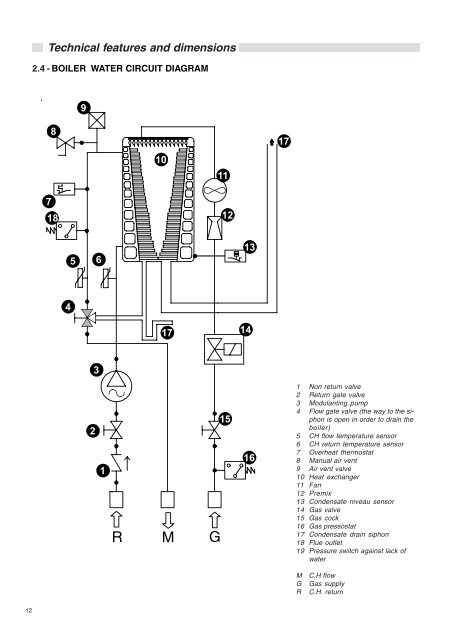
Technical features and dimensions2.4 - BOILER WATER CIRCUIT DIAGRAM98171011718125 61341714321RMG15161 Non return valve2 Return gate valve3 Modulanting pump4 Flow gate valve (the way to the siphonis open in order to drain theboiler)5 CH flow temperature sensor6 CH return temperature sensor7 Overheat thermostat8 <strong>Manual</strong> air vent9 Air vent valve10 Heat exchanger11 Fan12 Premix13 Condensate niveau sensor14 Gas valve15 Gas cock16 Gas pressostat17 Condensate drain siphon18 Flue outlet19 Pressure switch against lack ofwaterMGRC.H flowGas supplyC.H. return12
2.5 - PERFORMANCE DATA ACCORDINGTO STANDARD UNI 10348Minimum heat imputNominal heat imputNominal heat outoutMinimum heat outputEfficiency at full load (100%)Required efficiency at full load (100%)Efficiency at 30% part loadRequired efficiency at part load (30%)Nominal heat output in condensing modeMinimum heat ouput in condensing modeEfficiency at nominal load (100%) in condensing modeRequired efficiency (100%) in condensing modeEfficiency at 30% part load in condensing modeRequired efficiency at part load (30%) in condensing modeNumber of stars (according to CEE 92/42 and D.P.R. n° 660)Combustion efficiency at nominal load (100%)Combustion efficiency at part load (30%)Stand-by losses (min-max)(*) Flue gas temperature tf-ta (max)Flue gas mass flow rate (min-max)Air excess λCondensate production maxCO 2(min - max)CO at 0% of O (min - max)2N0x (value according to EN 297/A3 and EN 483N0x classFlue losses with burner in operation (min-max)Flue losses with burner off(*) Room Temperature = 20°C2.6 - GENERAL FEATURESAppliance’s family gas categoryMin. water flow rate in CH circuit (Δt 20 °C)Min. pressure in CH circuitMax. pressure in CH circuitMin. dynamic gas pressure (natural gas)<strong>Water</strong> content in primary circuitMax operating temp. in CH modeMin operating temp. in CH modeTotal volume CH expansion vesselTotal pre-loading expansion vesselMax water content CH circuit (calculated for a max temp. of 82°C)Min flow rate DHW circuitMin. DHW inlet pressureMax DHW inlet pressureDHW specific flow rate ( t 30 °C)DHW flow restrictorDHW production in continuous operation with t 45 KDHW production in continuous operation with t 40 KDHW production in continuous operation with t 35 KDHW production in continuous operation with t 30 K (*)DHW production in continuous operation with t 25 K (*)DHW adjustable temperatureElectrical supply /power consumptionFuse ratingMaximum absorbed power (with optional modulating pump)Electrical protectionNet weightTechnical features and dimensionsFor information regarding the adjustment of: INJECTORS - BURNER PRESSURES – DIAPHRAGMS– OUTPUTS – GAS CONSUMPTIONS please refer to the paragraph ADAPTMENT TO THE USE OFOTHER GASES.ALKON 90kW 22kW 90kW 87,5kW 21,1% 97,26% 96,88% 105,2% 94,83kW 93,6kW 24,0% 104,0% 92,97% 108,64% 98,97n. 4% 98,15% 98,31% 2,29 - 0,90°C 38,5g/s 8,7 - 39,1% 19,4kg/h 14,54% 8,8 - 9,6mg/kWh 21,5 - 104,4mg/kWh 35,625% 1,69 - 1,85kW 0,235l/minbarbarmbarl°C°Clbarllbarbarl/min.l/min.l/min.l/min.l/min.l/min.l/min.°CV-HzA (F)WIPkgALKON 90II 2H3P15,140,5814108530--------------230/504303X5D13513