Installation Manual - Unical Lattner Condensing Hot Water Boilers
Installation Manual - Unical Lattner Condensing Hot Water Boilers
Installation Manual - Unical Lattner Condensing Hot Water Boilers
- No tags were found...

You also want an ePaper? Increase the reach of your titles
YUMPU automatically turns print PDFs into web optimized ePapers that Google loves.
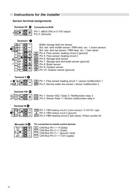
IInstructions for the installerSensor terminal assignmentsFATerminal VIIeBUS0-10 V12VIIConnection to BCMVIIPin 1: eBUS (FA) or 0-10V outputPin 2: (Ground)Terminal IIFBRAF KF / SPF VFF9 F8 F6 F5 F3 F2 F19 8 7 6 5 4 3 2 110VFVFSPFSPFKFAFAFBuffer storage tank low sensorBuf. stor. tank middle sensor / FBR heat. circ. 1 (room sensor)Buf. stor. tank top sensor / FBR heat. circ. 1 (set value)Pin 4: Flow sensor, heating circuit 2 (ground)Pin 5: Flow sensor, heating circuit 2Pin 6: Storage tank sensorPin 7: Storage tank and boiler sensor (ground)Pin 8: Boiler sensorPin 9: Outdoor sensorPin 10: Outdoor sensor (ground)Terminal V VSPFVFF12 F112 V 1VFSPFPin 1: Flow sensor heating circuit 1 / sensor multifunction 1Pin 2: Service water low sensor / sensor multifunction 2Terminal VIIIPT1000F14 F132 VIII 1F13F14Pin 1: Sensor HS2 / Solar 2 / Multifunction relay 3Pin 2: Sensor Solar 1 / Sensor multifunction relay 4FBR3 1Terminal III IIIIMP 0-10 V1F17 F15III23F15F17Pin 1: FBR heating circuit 2 (room sensor) / 0-10V IN / LightPin 2: FBR heating circuit 2 (ground)Pin 3: FBR heating circuit 2 (set value) / Pulse counter forMorsetto IX IXBUSL HIX4 3 2 1For connection to remote control devicesHL-+CAN Bus Pin 1 = H (Data)CAN Bus Pin 2 = L (Data)CAN Bus Pin 3 = - (ground, Gnd)CAN Bus Pin 4 = + (12V supply)30