RAF Be2c British Reconnaissance Aircraft from 1915
RAF Be2c British Reconnaissance Aircraft from 1915
RAF Be2c British Reconnaissance Aircraft from 1915

You also want an ePaper? Increase the reach of your titles
YUMPU automatically turns print PDFs into web optimized ePapers that Google loves.
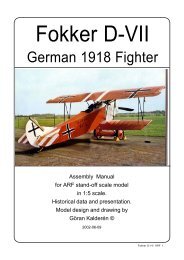
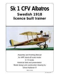
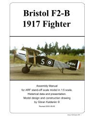
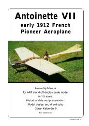
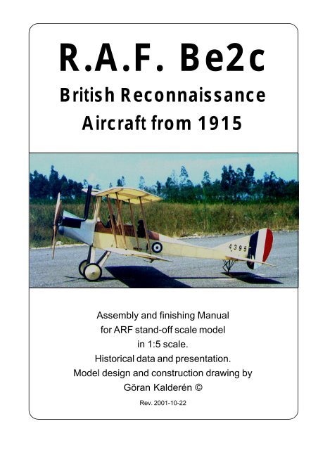
R.A.F. <strong>Be2c</strong><br />
<strong>British</strong> <strong>Reconnaissance</strong><br />
<strong>Aircraft</strong> <strong>from</strong> <strong>1915</strong><br />
Assembly and finishing Manual<br />
for ARF stand-off scale model<br />
in 1:5 scale.<br />
Historical data and presentation.<br />
Model design and construction drawing by<br />
Göran Kalderén ©<br />
Rev. 2001-10-22
Royal <strong>Aircraft</strong> Factory B.E. 2c<br />
Early B.E. 2s saw service with the Royal<br />
Flying Corps <strong>from</strong> 1912 onwards. The B.E.2c<br />
operated in France, mainly for reconnaissance<br />
and military observation, although some were<br />
single-seat bombers. Single-seat B.E.2c night<br />
fighters downed six dirigibles over Britain. Withdrawn<br />
<strong>from</strong> action in 1917, many continued as<br />
trainers until the war’s end. In all, 3 260 B.E. 2s<br />
were built.<br />
A B.E.2 became the first <strong>British</strong> aircraft<br />
to fly across the Channel and land in France after<br />
the outbreak of World War I. All models of<br />
the B.E. 2 had such great stability that they could<br />
nearly fly themselves during reconnaissance and<br />
Royal <strong>Aircraft</strong> Factory <strong>Be2c</strong> ARF 2<br />
artillery observation missions. While an easy<br />
target in the air over France, the B.E.2c’s stability<br />
contributed to its success as a single-seat<br />
home-defence fighter against German airships<br />
in night raids over England.<br />
A <strong>Be2c</strong> is on display in the Imperial War<br />
Museum in Lambeth, London, England. The museum<br />
example was manufactured in <strong>1915</strong> by<br />
the <strong>British</strong> and Colonial Aeroplane Company Ltd.,<br />
later known as the Bristol Aeroplane Company,<br />
Great Britain. This is knowingly one of the only<br />
two specimen of this styp still existing today. The<br />
other aircraft is in the Musée de l'Air, in Paris<br />
and is now being restored.<br />
Our model has the color scheme of an<br />
aircraft that served in Arabia in <strong>1915</strong>.
A Be2d is on display in National Aviation<br />
Museum, Canada. This aircraft differs externally<br />
very little <strong>from</strong> the c-model. The museum example<br />
was manufactured in <strong>1915</strong> by the <strong>British</strong><br />
and Colonial Aeroplane Company Ltd., later<br />
known as the Bristol Aeroplane Company, Great<br />
Britain. This aircraft is pictured on the opposite<br />
page. Above and below the <strong>Be2c</strong> on display in<br />
Imperial War Museum, in Lambeth, London.<br />
There are two excellent reference books available:<br />
<strong>RAF</strong> BE2C by J M Bruce, Windsock Datafile # 42,<br />
Albatros Productions Ltd., 10 Long View,<br />
Berkamstead, Herts. HP4 1BY, United Kingdom.<br />
ISBN # 0 948414-52-9.<br />
BE2 in action, <strong>Aircraft</strong> Number 123 by Peter<br />
Cooksley, Squadron/Signal Publications Inc. 1115<br />
Crowley Drive, Carrollton. Texas 75011-5010.<br />
ISBN # 0 89747-275-6<br />
Royal <strong>Aircraft</strong> Factory <strong>Be2c</strong> ARF 3
Royal <strong>Aircraft</strong> Factory <strong>Be2c</strong> ARF 4<br />
Details of the <strong>Be2c</strong> in<br />
the Imperial War<br />
Museum, Lambeth,<br />
London. The covering<br />
shows wear by the<br />
exposure and the rigging<br />
alignement should be<br />
reworked.<br />
The cockpit is sparsely<br />
equipped. Some of the<br />
instruments are visible<br />
in the picture above.<br />
The fin is of an enlarged<br />
type used on later<br />
aircraft
Details of the <strong>Be2c</strong> in the<br />
Imperial War Museum,<br />
Lambeth, London.<br />
This aircraft has no windshield<br />
which was unusual.<br />
The center section of the upper<br />
wing has a cut-out that was<br />
applied to some aircraft.<br />
The observer had small cut-out<br />
windows on both sides in the<br />
front of the cockpit covering to<br />
enable an improved downward<br />
view.<br />
The V-8 engine with dual<br />
exhaust stacks, typical for this<br />
aircraft.<br />
The rib stitching is clearly<br />
visible on this view of the<br />
undersid of the wingtip.<br />
Unfortunately also, that over the<br />
years, the trailing edge has<br />
become warped.<br />
Royal <strong>Aircraft</strong> Factory <strong>Be2c</strong> ARF 5
Royal <strong>Aircraft</strong> Factory <strong>Be2c</strong><br />
Wing Span: 36 ft 10 in (11.2 m)<br />
Length: 27 ft 3 in (8.3 m)<br />
Height: 11 ft 4 in (3.5 m)<br />
Weight, Empty: 1,370 lb (621 kg)<br />
Weight, Gross: 2,142 lb (972 kg)<br />
Royal <strong>Aircraft</strong> Factory <strong>Be2c</strong> ARF 6<br />
Max Speed: 90 mph (145 km/h)<br />
Rate of Climb: 6,500 ft (1,980 m)/20 min<br />
Service Ceiling: 10,000 ft (3,050 m)<br />
Range: 4 hours (Endurance)<br />
Power Plant: <strong>RAF</strong> 1a, 90 hp, Vee engine
The Model<br />
We have chosen the scale of 1:5 rendering<br />
a model size that i easy to fly but also relatively<br />
easy to transport. Both the upper and the lower<br />
wing panels can be removed as an assembly, for<br />
transportation which gives relatively limited<br />
requirement for transportation size.<br />
The finished model is painted in <strong>1915</strong> livery<br />
and further detailing can be made as per<br />
documentation.<br />
Specification:<br />
Wingspan 88.4" (225 cm)<br />
Length 65.4" (161 cm)<br />
Wing area 2281 sq/inch (142,6 dm²)<br />
Weight 13.7 lbs (6200 g)<br />
Wing Load (15oc/sq' (43 g/dm²)<br />
Engine .90 cu/inch 4-cycle(15 cc)<br />
Covering and finish<br />
The model is covered and painted <strong>from</strong> the<br />
factory. If you have made changes in the engine<br />
bearers and adapted the dummy engine to fit on<br />
both sides of the engine, you will have to cover<br />
the open areas with fuel proof paint.<br />
Installation of engine.<br />
We recommend that you don't overpower<br />
this model. It will fly happily with a .90 standard 4stroke<br />
engine. Our prototype was tried with a<br />
Thunder Tiger .90 4-stroke engine, which gave<br />
more than ample thrust. The engine bearers have<br />
been adjusted for this size of engine.<br />
The engine is mounted upright justifying the<br />
need for adequate cooling. The engine thereby<br />
is located in the "V" of the dummy engine and<br />
covered by the "air scoop" top plate.<br />
1. Remove the air scoop and drill the holes<br />
in the engine plywood bearers. Fasten the engine<br />
with blind nuts on the underside of the plywood.<br />
Place the engine as close to the front as possible.<br />
The propeller should be approx 1/8" / 3mm) it front<br />
of the nose cowl.<br />
2. Drill the holes <strong>from</strong> the tank to the<br />
carburator, pressure tap and the filling cap.<br />
3. Install the engine and connect the throttle<br />
servo.<br />
4. Make cut outs in the dummy engine block<br />
so that this will fit in line with your engine. This<br />
"surgery" is executed by removing a little at the<br />
time and checking. When you are satisfied with<br />
the fit and openings, screw the dummy engine<br />
onto the engine mount board, using screws and<br />
washers <strong>from</strong> under the plywood engine mount.<br />
5. Reinstall the engine cowl scoop (cowl)<br />
using 4 #2 sheet metal screws.<br />
Installation of servos, tank, battery and<br />
receiver.<br />
The 2 aileron servos are installed in the<br />
lower part of the servo vertical bulkhead in the<br />
fuselage side by side using the center holes<br />
commonly for the servos. The servo arms should<br />
protrude below the fuselage. It may be necessary<br />
to remove som plastoc <strong>from</strong> the servo housing to<br />
get the servos in place..<br />
The elevator servo and the rudder servo<br />
are installed in the servo tray. The tank is<br />
positioned below the plywood engine mount and<br />
in line with and behind the engine.<br />
The throttle servo is installed bihind the<br />
fire wall together with the battery pack.<br />
The receiver are positioned in the upper<br />
part of the fuselage between the two cockpits.<br />
The switch can be mounted on the servo<br />
tray with extension rod or on the instrument panel.<br />
1. Attach a ball link head to joystick and<br />
rudder bar in the appropriate holes. You may have<br />
to enlarge the holes to take the screw <strong>from</strong> the<br />
ball link (Dubro #189 set of 2).<br />
2. Install the servos for rudder and elevator<br />
and temporarily connect the servo arms to the<br />
ball links. Deflection for elevator is 20° up and<br />
down and for rudder 30° right and left..<br />
3. Install and connect the throttle servo in<br />
the fashion you prefer.<br />
4. Install the tank in the available space<br />
under the plywood engine bearer<br />
5. Install the aileron servos in the bulkhead.<br />
The aileron connecting wires attaches to the<br />
servo arms. The upper part of the servo arms<br />
are connected thus giving double thrust to the<br />
ailerons. Deflection of the ailerons should be 20°<br />
up and down.<br />
6. Install the radio switch on the dash board<br />
or the rear support in the front cockpit<br />
7. Place the receiver and the battery pack<br />
in the upper part of the trays, wrapped in foam<br />
rubber and secure with rubber bands.<br />
Assembly of the <strong>Be2c</strong><br />
All parts have been assembled at the factory<br />
and only disassembled for transportation. On<br />
recent production (serial # 9912-26 and higher)<br />
the landing gear has been made removable. The<br />
landing gear is pushed into the holes in the<br />
fuselage and held in position by the 2 cross<br />
bracing wires.<br />
Rudder and elevator wires are factory<br />
adjusted but may need some tensioning<br />
adjustment after a while. Aileron can be adjusted<br />
with the clevices connecting to the aileron horns.<br />
Assembly of wing panels<br />
1. Push the lower wing halves into the holes<br />
in the fuselage.<br />
2. Push the upper wing halves into the holes<br />
in the wing cabane. Connect the flying wires and<br />
the landing wires. Attach the flying wires in place.<br />
Royal <strong>Aircraft</strong> Factory <strong>Be2c</strong> ARF 7
These are the rigging wires:<br />
1. Rudder control wires<br />
2. Elevator control wires<br />
3. Front flying wires<br />
4. Rear flying wires.<br />
5. Front landing wires<br />
Attach the landing wires in place.<br />
3. Install the interplane struts. Note that the<br />
approx. 1/8" shorter struts fit in the front positions.<br />
Connect the strut cross bracing by clipping the<br />
kwick links in place.<br />
4. Now connect the aileron wires to the<br />
aileron horns. Note that these wires go <strong>from</strong> the<br />
Servo arm<br />
Attach center<br />
section with<br />
2pcs 2 mm<br />
screws, one<br />
<strong>from</strong> each<br />
side<br />
1<br />
11<br />
9<br />
Cut <strong>from</strong><br />
nylon horn<br />
Royal <strong>Aircraft</strong> Factory <strong>Be2c</strong> ARF 8<br />
7<br />
11<br />
Move piece up<br />
for less throw.<br />
Reverse piece<br />
for more throw.<br />
throw.<br />
4<br />
8<br />
6<br />
3<br />
5<br />
2<br />
11<br />
Kwik-link to<br />
aileron wire.<br />
Drill 3 holes<br />
1,5 mm diam<br />
4<br />
3<br />
8<br />
10<br />
6. Rear landing wires.<br />
7. Interplane strut bracing wires.<br />
8. Cabane bracing wires.<br />
9. Fin - stabilizer support wires.<br />
10. Landing gear bracing wires.<br />
11 Aileron control wires.<br />
servo arms in the bottom of the fuselage,<br />
under the lover wings, via pulleys to the aileron<br />
horns.<br />
From the top of the lover ailerons to the<br />
bottom of the upper ailerons. From the upper<br />
aileron horns via pulleys on top of the upper wings<br />
to the centre brass guides and connected there<br />
to each other with an adjustable linking device.<br />
Should you need to replace a wire, use the<br />
attachment method indicated in the picture. When<br />
crimping the cerulet (sleeve) use a flat plier or a<br />
crimping tool, press firmly and don't cut through<br />
the wire.<br />
Landing gear<br />
1. Install the wheels on the shaft and secure<br />
with the stoppers.<br />
2.Lace rubber bands in the fashion shown
in the sketch. This is a very efficient shock<br />
absorber.<br />
Balancing<br />
The center of gravity / balancing point<br />
should be approx. approx. 13 cm (5.2")<br />
measured <strong>from</strong> the leading edge on the upper<br />
wing. Make adjustments if necessary.<br />
Flying<br />
The prototype was flown with a Thinder<br />
Tiger .90 4-stroke engine. Let the engine swing<br />
a 16x6 propeller if possible. This gives better<br />
thrust and reduces sound to a more realistic level.<br />
Remember this is a slow flying aircraft.<br />
Flying characteristics are very forgiving<br />
and will fly happily on 2/3 throttle. Set the elevator<br />
at zero angle for the first flight but be prepared<br />
to give down elevator if the model climbs out too<br />
steep. During the initial take off run you have to<br />
compensate for the torque with right rudder but<br />
as the speed builds up the rudder is returned to<br />
neutrual. This model should fly of the ground and<br />
not be pulled. Once airborn the aircraft is as its<br />
full size prototype. Remember: climb or decent is<br />
controlled with the throttle, speed with the elevator.<br />
Start the turns with the rudder, then use up<br />
elevator. It will be necessary at this time to give<br />
opposite aileron to dampen the turn rate.<br />
The landing approach can be rather steep<br />
as per prototype but the flare out needs almost<br />
full up elevator. Get the tail down to maintain<br />
directional stability.<br />
Happy landings!<br />
Turnbuckle for rigging<br />
Lacing of the bungee rubber<br />
on the landing gear<br />
Stabilizer incidence<br />
adjustment<br />
The aileron wires run on top of the upper wings and under the lover wings. Pulleys guide the wires.<br />
The rudder and elevator control wires run exteriorally to the respective control surfaces.<br />
Royal <strong>Aircraft</strong> Factory <strong>Be2c</strong> ARF 9
Rudder and elevator control is by wire <strong>from</strong> the<br />
rudder bar protruding <strong>from</strong> the fuselage and by<br />
the exterior elevator conttrol horns. The pilots<br />
seat is on top of the elevator connecting rod<br />
(above). The rudder and elevators are connected<br />
by pull-pull wires (below). The stabilizer is<br />
attached to the fuselage by 3,5 mm wires through<br />
the fuselage. The front attachment is adjustable<br />
Royal <strong>Aircraft</strong> Factory <strong>Be2c</strong> ARF 10<br />
vertically te permit alteration of the<br />
stabilizer incidence by turning the<br />
adjustment screws in the bottom if the<br />
fuselage. The whole tail unit is<br />
secured with adjustable bracing wires.<br />
The ailerons are controled in a closed<br />
loop wire system. The wires are<br />
located externally on top of the upper<br />
wing and under the bottom of the lower<br />
wing (above) The upper and lower<br />
ailerons are connected by adjustable<br />
wire. In the bottom of the fuselage 2<br />
servos with the arms protruding<br />
through the fuselage bottom are<br />
driving the wires to the lower wing
ailerons. The wing cabane is supported by cross<br />
wire bracing. The observers cockpit is in the front<br />
and the pilots cockpit in the rear. The dummy<br />
engine (above) is enclosing the installed .90 4cycle<br />
model engine (Thunder Tiger .90). For<br />
display models without flying engine, the dummy<br />
SAITO .90, 4-stroke<br />
engine installed inside<br />
the R.A.F V-8<br />
dummy engine<br />
engine has a complete motor block. The exhaust<br />
stacks have a support on the upper wing center<br />
section that also serves as wing joint. Lead<br />
channels for the upper aileron wire are located<br />
on the inter connecting pieces.<br />
Royal <strong>Aircraft</strong> Factory <strong>Be2c</strong> ARF 11
What is in the box:<br />
The ARF kit contains the parts shown in the picture.<br />
All the parts are covered and painted. All the rigging<br />
6<br />
4<br />
5<br />
1. Fuselage with wing cabane<br />
2. Landing gear<br />
3. Scale wheels<br />
4. Engine cowl<br />
5. Dummy engine with mount<br />
6. Scale propeller<br />
7. Tail skid assy.<br />
8. Fin with rudder<br />
K&W<br />
14<br />
Model<br />
Airplanes Inc.<br />
Royal <strong>Aircraft</strong> Factory <strong>Be2c</strong> ARF 12<br />
3<br />
2<br />
1<br />
wires are supplied in the correct lengths and need<br />
only to be clipped to their positions.<br />
10<br />
12<br />
12<br />
11<br />
12<br />
7<br />
9. Stabilizer / elevator<br />
10. Upper wing panels<br />
11. Lower wing panels<br />
12. Interplane struts<br />
13. Wires, turnbuckles and hardware for assembly<br />
(not shown)<br />
14. Assembly manual with scale<br />
documentation<br />
P.O.Box 1229, Cebu City Centrl. Postoffice<br />
Cebu City 6000, Philippines<br />
Visiting address:<br />
3343 Gun-Ob, Kinalumsan,<br />
Lapu-Lapu City 6015, PHILIPPINES<br />
Phone +63 32-340 0772, Cellular +63 917-3200 985<br />
Telefax +63 32-340 7131, E-mail: kwmairpl@gsilink.com<br />
Website: www.kwmairpl.com.ph<br />
9<br />
8