RAF Be2c British Reconnaissance Aircraft from 1915
RAF Be2c British Reconnaissance Aircraft from 1915
RAF Be2c British Reconnaissance Aircraft from 1915

Create successful ePaper yourself
Turn your PDF publications into a flip-book with our unique Google optimized e-Paper software.
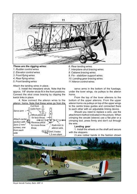
These are the rigging wires:<br />
1. Rudder control wires<br />
2. Elevator control wires<br />
3. Front flying wires<br />
4. Rear flying wires.<br />
5. Front landing wires<br />
Attach the landing wires in place.<br />
3. Install the interplane struts. Note that the<br />
approx. 1/8" shorter struts fit in the front positions.<br />
Connect the strut cross bracing by clipping the<br />
kwick links in place.<br />
4. Now connect the aileron wires to the<br />
aileron horns. Note that these wires go <strong>from</strong> the<br />
Servo arm<br />
Attach center<br />
section with<br />
2pcs 2 mm<br />
screws, one<br />
<strong>from</strong> each<br />
side<br />
1<br />
11<br />
9<br />
Cut <strong>from</strong><br />
nylon horn<br />
Royal <strong>Aircraft</strong> Factory <strong>Be2c</strong> ARF 8<br />
7<br />
11<br />
Move piece up<br />
for less throw.<br />
Reverse piece<br />
for more throw.<br />
throw.<br />
4<br />
8<br />
6<br />
3<br />
5<br />
2<br />
11<br />
Kwik-link to<br />
aileron wire.<br />
Drill 3 holes<br />
1,5 mm diam<br />
4<br />
3<br />
8<br />
10<br />
6. Rear landing wires.<br />
7. Interplane strut bracing wires.<br />
8. Cabane bracing wires.<br />
9. Fin - stabilizer support wires.<br />
10. Landing gear bracing wires.<br />
11 Aileron control wires.<br />
servo arms in the bottom of the fuselage,<br />
under the lover wings, via pulleys to the aileron<br />
horns.<br />
From the top of the lover ailerons to the<br />
bottom of the upper ailerons. From the upper<br />
aileron horns via pulleys on top of the upper wings<br />
to the centre brass guides and connected there<br />
to each other with an adjustable linking device.<br />
Should you need to replace a wire, use the<br />
attachment method indicated in the picture. When<br />
crimping the cerulet (sleeve) use a flat plier or a<br />
crimping tool, press firmly and don't cut through<br />
the wire.<br />
Landing gear<br />
1. Install the wheels on the shaft and secure<br />
with the stoppers.<br />
2.Lace rubber bands in the fashion shown