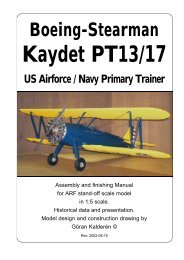
RAF Be2c British Reconnaissance Aircraft from 1915
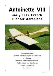
RAF Be2c British Reconnaissance Aircraft from 1915
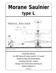
RAF Be2c British Reconnaissance Aircraft from 1915

Create successful ePaper yourself
Turn your PDF publications into a flip-book with our unique Google optimized e-Paper software.
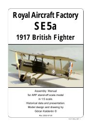
The Model<br />
We have chosen the scale of 1:5 rendering<br />
a model size that i easy to fly but also relatively<br />
easy to transport. Both the upper and the lower<br />
wing panels can be removed as an assembly, for<br />
transportation which gives relatively limited<br />
requirement for transportation size.<br />
The finished model is painted in <strong>1915</strong> livery<br />
and further detailing can be made as per<br />
documentation.<br />
Specification:<br />
Wingspan 88.4" (225 cm)<br />
Length 65.4" (161 cm)<br />
Wing area 2281 sq/inch (142,6 dm²)<br />
Weight 13.7 lbs (6200 g)<br />
Wing Load (15oc/sq' (43 g/dm²)<br />
Engine .90 cu/inch 4-cycle(15 cc)<br />
Covering and finish<br />
The model is covered and painted <strong>from</strong> the<br />
factory. If you have made changes in the engine<br />
bearers and adapted the dummy engine to fit on<br />
both sides of the engine, you will have to cover<br />
the open areas with fuel proof paint.<br />
Installation of engine.<br />
We recommend that you don't overpower<br />
this model. It will fly happily with a .90 standard 4stroke<br />
engine. Our prototype was tried with a<br />
Thunder Tiger .90 4-stroke engine, which gave<br />
more than ample thrust. The engine bearers have<br />
been adjusted for this size of engine.<br />
The engine is mounted upright justifying the<br />
need for adequate cooling. The engine thereby<br />
is located in the "V" of the dummy engine and<br />
covered by the "air scoop" top plate.<br />
1. Remove the air scoop and drill the holes<br />
in the engine plywood bearers. Fasten the engine<br />
with blind nuts on the underside of the plywood.<br />
Place the engine as close to the front as possible.<br />
The propeller should be approx 1/8" / 3mm) it front<br />
of the nose cowl.<br />
2. Drill the holes <strong>from</strong> the tank to the<br />
carburator, pressure tap and the filling cap.<br />
3. Install the engine and connect the throttle<br />
servo.<br />
4. Make cut outs in the dummy engine block<br />
so that this will fit in line with your engine. This<br />
"surgery" is executed by removing a little at the<br />
time and checking. When you are satisfied with<br />
the fit and openings, screw the dummy engine<br />
onto the engine mount board, using screws and<br />
washers <strong>from</strong> under the plywood engine mount.<br />
5. Reinstall the engine cowl scoop (cowl)<br />
using 4 #2 sheet metal screws.<br />
Installation of servos, tank, battery and<br />
receiver.<br />
The 2 aileron servos are installed in the<br />
lower part of the servo vertical bulkhead in the<br />
fuselage side by side using the center holes<br />
commonly for the servos. The servo arms should<br />
protrude below the fuselage. It may be necessary<br />
to remove som plastoc <strong>from</strong> the servo housing to<br />
get the servos in place..<br />
The elevator servo and the rudder servo<br />
are installed in the servo tray. The tank is<br />
positioned below the plywood engine mount and<br />
in line with and behind the engine.<br />
The throttle servo is installed bihind the<br />
fire wall together with the battery pack.<br />
The receiver are positioned in the upper<br />
part of the fuselage between the two cockpits.<br />
The switch can be mounted on the servo<br />
tray with extension rod or on the instrument panel.<br />
1. Attach a ball link head to joystick and<br />
rudder bar in the appropriate holes. You may have<br />
to enlarge the holes to take the screw <strong>from</strong> the<br />
ball link (Dubro #189 set of 2).<br />
2. Install the servos for rudder and elevator<br />
and temporarily connect the servo arms to the<br />
ball links. Deflection for elevator is 20° up and<br />
down and for rudder 30° right and left..<br />
3. Install and connect the throttle servo in<br />
the fashion you prefer.<br />
4. Install the tank in the available space<br />
under the plywood engine bearer<br />
5. Install the aileron servos in the bulkhead.<br />
The aileron connecting wires attaches to the<br />
servo arms. The upper part of the servo arms<br />
are connected thus giving double thrust to the<br />
ailerons. Deflection of the ailerons should be 20°<br />
up and down.<br />
6. Install the radio switch on the dash board<br />
or the rear support in the front cockpit<br />
7. Place the receiver and the battery pack<br />
in the upper part of the trays, wrapped in foam<br />
rubber and secure with rubber bands.<br />
Assembly of the <strong>Be2c</strong><br />
All parts have been assembled at the factory<br />
and only disassembled for transportation. On<br />
recent production (serial # 9912-26 and higher)<br />
the landing gear has been made removable. The<br />
landing gear is pushed into the holes in the<br />
fuselage and held in position by the 2 cross<br />
bracing wires.<br />
Rudder and elevator wires are factory<br />
adjusted but may need some tensioning<br />
adjustment after a while. Aileron can be adjusted<br />
with the clevices connecting to the aileron horns.<br />
Assembly of wing panels<br />
1. Push the lower wing halves into the holes<br />
in the fuselage.<br />
2. Push the upper wing halves into the holes<br />
in the wing cabane. Connect the flying wires and<br />
the landing wires. Attach the flying wires in place.<br />
Royal <strong>Aircraft</strong> Factory <strong>Be2c</strong> ARF 7