

ULTRA Plus+ 1500 Airless Paint Sprayer - Graco Inc.
ULTRA Plus+ 1500 Airless Paint Sprayer - Graco Inc.
ULTRA Plus+ 1500 Airless Paint Sprayer - Graco Inc.

You also want an ePaper? Increase the reach of your titles
YUMPU automatically turns print PDFs into web optimized ePapers that Google loves.
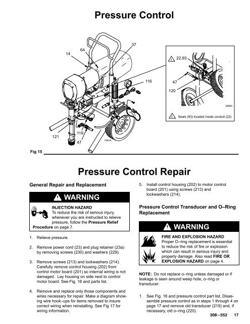
Pressure Control14643722,9311647120 Seals (93) located inside conduit (22)12111947Fig 15Pressure Control RepairGeneral Repair and ReplacementWARNINGINJECTION HAZARDTo reduce the risk of serious injury,whenever you are instructed to relievepressure, follow the Pressure ReliefProcedure on page 7.1. Relieve pressure.2. Remove power cord (23) and plug retainer (23a)by removing screws (230) and washers (229).3. Remove screws (213) and lockwashers (214).Carefully remove control housing (202) fromcontrol motor board (201) so internal wiring is notdamaged. Lay housing on side next to controlmotor board. See Fig. 16 and parts list.4. Remove and replace only those components andwires necessary for repair. Make a diagram showingwire hook–ups for items removed to insurecorrect wiring when reinstalling. See Fig 17 forwiring information.5. Install control housing (202) to motor controlboard (201) using screws (213) andlockwashers (214).Pressure Control Transducer and O–RingReplacementWARNINGFIRE AND EXPLOSION HAZARDProper O–ring replacement is essentialto reduce the risk of fire or explosionwhich can result in serious injury andproperty damage. Also read FIRE OREXPLOSION HAZARD on page 4.NOTE: Do not replace o–ring unless damaged or ifleakage is seen around weep hole, o–ring ortransducer.1. See Fig. 16 and pressure control part list. Disassemblepressure control as in steps 1 through 4 onpage 17 and remove old transducer (219) and, ifnecessary, old o–ring (220).


