

ULTRA Plus+ 1500 Airless Paint Sprayer - Graco Inc.
ULTRA Plus+ 1500 Airless Paint Sprayer - Graco Inc.
ULTRA Plus+ 1500 Airless Paint Sprayer - Graco Inc.

Create successful ePaper yourself
Turn your PDF publications into a flip-book with our unique Google optimized e-Paper software.
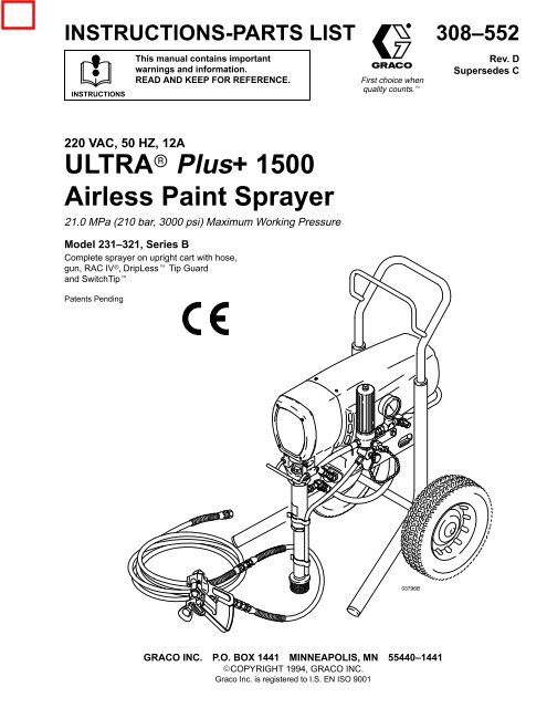
INSTRUCTIONS-PARTS LIST308–552INSTRUCTIONSThis manual contains importantwarnings and information.READ AND KEEP FOR REFERENCE.First choice whenquality counts.Rev. DSupersedes C220 VAC, 50 HZ, 12A<strong>ULTRA</strong> <strong>Plus+</strong> <strong>1500</strong><strong>Airless</strong> <strong>Paint</strong> <strong>Sprayer</strong>21.0 MPa (210 bar, 3000 psi) Maximum Working PressureModel 231–321, Series BComplete sprayer on upright cart with hose,gun, RAC IV, DripLess Tip Guardand SwitchTipPatents PendingGRACO INC. P.O. BOX 1441 MINNEAPOLIS, MN 55440–1441COPYRIGHT 1994, GRACO INC.<strong>Graco</strong> <strong>Inc</strong>. is registered to I.S. EN ISO 9001
SetupWARNINGFIRE AND EXPLOSION HAZARDProper electrical grounding is essentialto reduce the risk of fire or explosionwhich can result in serious injury andproperty damage. Also read FIRE OREXPLOSION HAZARD on page 4.1. Connect gun, 1 m hose (78) and 15 m hose (79).Don’t install spray tip yet.2. Two gun hookup. Remove cap (12) from 1/4npsm(m) secondary hose outlet and attach minimum15 m long hose. For more flexible gun movement,install 3/16 in. ID, 1 m whip hose betweenmain hose and gun.WARNINGIf you supply your own hoses and spray gun, besure the hoses are electrically conductive, thatthe gun has a tip guard, and that each part israted for at least 21.0 MPa (210 bar, 3000 psi)Working Pressure. This is to reduce the risk ofserious injury caused by static sparking, fluidinjection or over-pressurization and rupture ofthe hose or gun.CAUTIONTo avoid damaging the pressure control, which mayresult in poor equipment performance and componentdamage, follow these precautions:1. Always use a nylon spray hose at least 15 m (50ft.) long.2. Never use a wire braid hose as it is too rigid toact as a pulsation dampener.3. Never install any shutoff device between thesprayer outlet (D) and the hose. See Fig. 2.3. Fill packing nut/wet–cup (E)1/3 full with <strong>Graco</strong>Throat Seal Liquid (TSL), supplied.4. Check electrical service. Be sure electrical serviceis 220 V, 50 Hz. Use properly grounded outlet. Ifplug is wrong, have licensed electrician attachcorrect plug to power supply cord. Do not removegrounding prong of power supply cord. Do not usean adapter. Extension cords must have 3 wires ofminimum 2.5 mm (12 gauge) size. Long extensioncords reduce sprayer performance. Set 10/12 Ampswitch (C) to correct setting.5. With ON/OFF switch (A) OFF, plug cord into agrounded electrical outlet located at least 6 m (20ft.) away from spray area. See Fig. 26. Flush pump to remove lightweight oil which wasleft in to protect pump parts after factory testing.See page 10.12C78E79DB55ADo not install any shutoff device hereFill packing nut 1/3 full with TSL118Fig. 2
OperationPressure Relief ProcedureWARNINGPRESSURIZED EQUIPMENT HAZARDThe system pressure must be manuallyrelieved to prevent the system fromstarting or spraying accidentally. Toreduce the risk of an injury from accidental sprayfrom the gun, splashing fluid, or moving parts,follow the Pressure Relief Procedure wheneveryou: are instructed to relieve the pressure, stop spraying, check or service any of the system equipment, or install or clean the spray nozzle.1. Engage gun safety latch.2. Turn ON/OFF switch to OFF.StartupWARNINGINJECTION HAZARDTo reduce the risk of serious injury,whenever you are instructed to relievepressure, follow the Pressure ReliefProcedure above.Always use this procedure to help ensure sprayer isready to operate and that you start it safely. SeeFig. 21. For a first time startup, flush sprayer. See page 10.2. Close pressure drain valve (118).3. Don’t install spray tip until pump is primed!4. Put suction tube into paint container.5. Lower pressure setting by turning pressure adjustingknob (B) all the way counterclockwise.3. Unplug power cord.4. Disengage gun safety latch. Hold metal part of gunagainst grounded metal pail and trigger gun intopail to relieve pressure.6. Disengage gun safety latch. See Fig. 3.Gun safety latchshown engagedGun safety latchshown disengaged5. Engage gun safety latch.6. Open any fluid drain valves in system. Leave drainvalve open until ready to dispense again.Fig. 3
FlushingWhen to Flush1. New <strong>Sprayer</strong>. The sprayer is factory tested withlightweight oil which is left to protect pump parts.ACBefore using water–base paint, flush with mineralspirits, then warm, soapy water, and then cleanwater.BBefore using oil–base paint, flush with mineral spirits.D2. Changing Colors. Flush with compatible solvent.3. Changing from water–base to oil–base paint. Flushwith warm, soapy water, then mineral spirits.4. Changing from oil–base to water–base paint. Flushwith mineral spirits, then warm, soapy water, andthen clean water.EFig. 7F5. Storage. Flush as indicated below, shut off sprayer,open pressure drain valve to relieve pressureand leave open.Water–base paint: flush with water, then mineralspirits. Leave system filled with mineral spirits.Oil–base paint: flush with mineral spirits.CAUTIONNever allow water to freeze in the pressure control.Doing so prevents the sprayer from being startedand causes serious damage to the pressure control.Push the water out with mineral spirits.6. Startup after storage. Before using water–basepaint, flush out mineral spirits with soapy water andthen clean water. When using oil–base paint, flushout mineral spirits with the paint to be sprayed.How to Flush1. Relieve pressure.2. Remove filter bowl (C) and screen (D). Installbowl (C) and filter support (E) without screen (D)to flush. See Fig. 7.3. Close pressure drain valve (F).4. Pour 2 liters of compatible solvent into groundedmetal pail. Put suction tube in pail.5. Remove spray tip from gun. 6. Turn pressure adjusting knob (A) completelycounterclockwise to lowest pressure setting.WARNINGFIRE AND EXPLOSION HAZARDTo reduce static sparking and splashing,always remove the spray tip fromthe gun, and hold a metal part of thegun firmly to the side of a grounded metal pailwhen flushing.7. Hold metal part of gun firmly against metal wastecontainer. See Fig. 4. Trigger gun, turn sprayerswitch (B) on, and slowly increase pressure untilsprayer just starts. Keep gun triggered until all airis forced out of system and solvent flows freelyfrom gun. Release trigger and engage gun safetylatch.NOTE: If the pump is hard to prime, open the drainvalve. When fluid comes from the valve, close it.Proceed as in Step 7.8. Remove suction tube from pail. Disengage gunsafety latch and trigger gun to force solvent fromhose. Do not run pump dry for more than 30seconds to avoid damaging pump packings!Relieve pressure.9. Leave pressure drain valve (F) open until sprayeris used again.10. Clean filter screen (D) and reinstall. Reinstallbowl (C), hand tight only.11. If pump is flushed with mineral spirits and is to beused with water–base paint, flush with soapy waterand then clean water. Relieve pressure.
TroubleshootingTYPE OF PROBLEMMotor runs and pump strokes,but output is low or there is nooutput.WHAT TO CHECKIf check is OK, go to next checkWHAT TO DOWhen check is not OK refer to this columnCheck extension cord size and length. Replace cord with a larger size, groundingtype extension cord.Motor runs but pump does notstroke.Motor is hot and runsintermittently.Check paint supply.Check for clogged intake strainer.Check for loose suction tube or loose fittings.Check for worn spray tip.Check motor brushes; check for loose leadsand terminals, minimum 13 mm brush length,broken or misaligned springs, or brushesbinding in holders. See page 13.Check motor armature for shorts by using anarmature tester (growler).Check to see if pump continues to strokewhen gun trigger is released. With pump onand primed, trigger gun momentarily, thenrelease and engage safety latch. Relievepressure, turn off and unplug sprayer.Check to see if intake valve ball and pistonball are seating properly.Check for leaking around throat packing nutwhich may indicated worn or damagedpackings.Defective pressure control transducer.Check displacement pump connecting rodpin (20). See page 15.Check for frozen or hardened paint in thepump (39).Be sure crank in drive housing rotates; plugin sprayer and turn on briefly to check. Turnoff and unplug sprayer.Determine if sprayer was operated at highpressure with small tips, which causes lowmotor RPM and excessive heat build up.Be sure ambient temperature where sprayeris located is no more than 32C and sprayeris not located in direct sun.Determine in sprayer was turned on,pressurized, but not operating for longperiods of time.Refill and reprime pump.Remove and clean strainer and reinstall.Tighten; use thread sealant or sealing tape onthreads, if necessary.Follow Pressure Relief ProcedureWarning, then replace tip. See yourseparate gun or tip manual.Replace parts as needed. See page 13.Replace motor. See page 20.Service pump. See manual 307–806.Remove intake valve and clean. Check ballsand seats for nicks; replace if necessary.See manual 307–806. Strain paint beforeusing to remove particles that could clog thepump.Replace packings. See manual 307–806.Also check piston valve seat for hardenedpaint or nicks and replace if necessary.Tighten the packing nut/wetcup.Replace pressure control transducer. Seepage 17.Replace pin, if missing. Be sure retainerspring (35) is fully in groove all aroundconnecting rod. See page 15.Thaw. See NOTE 1. Plug in sprayer and turnon. Slowly increase pressure setting to see ifmotor starts.Check drive housing assembly for damageand replace if necessary. See page 23.Decrease pressure setting or increase tipsize.Move sprayer to shaded, cooler area, ifpossible.Turn off sprayer whenever you stop sprayingfor a while and relieve fluid pressure.NOTE 1: Thaw the sprayer if water or water–based paint has frozen in it, by placing it in a warm area. Do not try tostart the sprayer until it has thawed completely. If paint hardened (dried) in the sprayer, replace the pump packings.See manual 307–806.
-Motor Brush ReplacementELECTRIC SHOCK HAZARDTo reduce the risk of Electric Shock: wait5 minutes after turning sprayer off beforeservicing to allow stored current to discharge.WARNINGNOTE: Replace the brushes when they have worn toless than 10 mm. See Fig. 10. Always replace bothbrushes at the same time. A Brush Repair Kit, p/n222–157, and spring clip, p/n 110–816, are available.NOTE: To maximize replacement brush life, break in newbrushes by operating the sprayer with no load for at leastone hour. To operate with no load, remove the pumpconnecting rod pin.WARNINGINJECTION HAZARDTo reduce the risk of serious injury,whenever you are instructed to relievepressure, follow the Pressure ReliefProcedure on page 7.Fig. 8A141. Remove motor cover (14) and both inspectioncovers (A). See Fig. 8.2. Push in spring clip (D) to unhook, and then pullout. See Fig. 9.3. Loosen terminal screw (F). Pull brush lead (E)away, leaving motor lead (G) in place. Removebrush (C) and spring (B). See Fig. 10.4. Inspect commutator for excessive pitting, burningor gouging. A black color on commutator is normal.Have commutator resurfaced by qualified motorrepair shop if brushes seem to wear too fast.5. Install new brush (C) so lead is in long slot (H) ofholder. See Fig. 11. Slide the terminal (E) underthe terminal screw washer. Make sure motorlead (G) is still connected the at screw. Tightenscrew (F). See Fig. 10.6. Place spring (B) on brush as shown in Fig. 11.Spring must coil as shown.7. Push in and hook spring clip (D). See Fig. 11.8. Repeat for other side.9. Test brushes. Remove connecting rod pin (20).See Fig. 13, page 15. With sprayer off, turn pressurecontrol knob fully counterclockwise to minimumpressure. Plug in sprayer. Turn sprayer on.Slowly increase pressure until motor is at fullspeed. Inspect brush and commutator contactarea for excessive arcing. Arcs should not “trail” orcircle around commutator surface.CAUTIONDo not touch the brushes, leads, springs or brushholders while the sprayer is plugged in, to reduce therisk of electric shock and serious bodily injury.10. Install brush inspection plates, gaskets, and covers.11. Break in brushes. Operate sprayer for at least onehour with no load. Then reinstall connecting rodpin (20).
-Motor Brush ReplacementBHBCOrder part no. 110–816CD Hook of spring clipFig. 9D Spring mustcoil in thisdirectionBDFig. 11CFig. 1010 mm minimumGEF
Removing and Installing PumpWARNINGINJECTION HAZARDTo reduce the risk of serious injury,whenever you are instructed to relievepressure, follow the Pressure ReliefProcedure on page 7.Removal See Fig. 12.1. Flush pump, if possible. Relieve pressure again.Stop pump with piston rod in lowest position, ifpossible.CAUTIONIf the locknut (38) loosens during operation, thethreads of the bearing housing (27) will be damaged.Be sure to tighten the locknut firmly.3. Tighten packing nut/ wet-cup just enough to stopleakage, but no tighter. Fill wet–cup/packing nut1/3 full with <strong>Graco</strong> TSL.2. Disconnect drain tube (101) from pump (39) andsuction tube (42).3. Remove suction tube (42); hold wrench on pumpintake valve (223) to keep pump from loosening.4. Remove hose (47).5. Push retaining spring (35) up and push outpin (20).6. Loosen locknut (38) and unscrew pump frombearing housing (27).Installation See Fig. 12 and 13.1. Screw displacement pump into bearinghousing (27) until pin hole in connecting rod assembly(29) and displacement rod (A) align. Installpin (20).2735A2038101Fig. 124739223422. Continue to screw pump into bearing housing untiltop threads of pump cylinder are flush with face ofbearing housing and outlet nipple (75) is straightback. Push retaining spring (35) into groovearound connecting rod. Tighten locknut (38) to95 N.m (70 ft-lb).Face of bearing housingTorque to 95 N.m (70 ft–lb)WARNINGMOVING PARTS HAZARDBe sure the retaining spring (35) is firmlyin the groove of the connecting rod, allthe way around, to prevent it from workingloose due to vibration.29352720If the pin works loose, it or other parts could breakoff due to the force of the pumping action. Theseparts could be projected through the air and resultin serious bodily injury or property damage, includingdamage to the pump, connecting rod or bearinghousing.Fig. 137538
Pressure ControlCAUTIONDo not install the pressure control until motor ischecked. A defective motor may damage the pressurecontrol. Make sure to test the motor prior topressure control installation.ELECTRIC SHOCK HAZARDTo reduce the risk of Electric Shock: wait5 minutes after turning sprayer off beforeservicing to allow stored current to discharge.Motor TestWARNINGWith motor shield off and four motor leads disconnected:Check continuity with multimeter from each blackmotor lead to ground (one at a time). Any readingless than infinite resistance – even very high resistance– means motor is shorted to ground. Replacemotor.CAUTIONA motor that is shorted to ground will damage thepressure control.2. Remove fan cover from motor.3. Remove pump pin ( See page 15 for instructions toremove pin).8. Install pump pin and fan cover.WARNINGINJECTION HAZARDTo reduce the risk of serious injury,whenever you are instructed to relievepressure, follow the Pressure ReliefProcedure on page 7.1. Relieve pressure.2. Remove ten screws (64) and motor shield (14).See Fig. 15 and parts list, except as noted.3. Loosen outlet cover on pressure control wiringbox. Disconnect motor leads. See Fig 14.4. Loosen black conduit (22) from pressure controlfitting and pull out wires5. Remove hose (47) from rear of pressure control(116).6. Remove hose (121) and 45 swivel union (119)from front of pressure control (116).7. Support pressure control (116) and carefully removemotor mount screws (37). Remove pressurecontrol.8. Install new pressure control (116) with screws (37).9. Continue to assemble sprayer.4. With black motor leads not connected, use motorfan to spin motor quickly. Motor should spin freelyin both directions. If not, replace motor.BlackBlack5. Connect black motor leads together.6. Use motor fan to turn motor. It should be muchharder to turn than in step 4. If there is uneven orno resistance to turning, check brushes and replaceif necessary.7. If there is still uneven or no resistance to turning,replace motor.Fig 14RedYellow
Pressure Control14643722,9311647120 Seals (93) located inside conduit (22)12111947Fig 15Pressure Control RepairGeneral Repair and ReplacementWARNINGINJECTION HAZARDTo reduce the risk of serious injury,whenever you are instructed to relievepressure, follow the Pressure ReliefProcedure on page 7.1. Relieve pressure.2. Remove power cord (23) and plug retainer (23a)by removing screws (230) and washers (229).3. Remove screws (213) and lockwashers (214).Carefully remove control housing (202) fromcontrol motor board (201) so internal wiring is notdamaged. Lay housing on side next to controlmotor board. See Fig. 16 and parts list.4. Remove and replace only those components andwires necessary for repair. Make a diagram showingwire hook–ups for items removed to insurecorrect wiring when reinstalling. See Fig 17 forwiring information.5. Install control housing (202) to motor controlboard (201) using screws (213) andlockwashers (214).Pressure Control Transducer and O–RingReplacementWARNINGFIRE AND EXPLOSION HAZARDProper O–ring replacement is essentialto reduce the risk of fire or explosionwhich can result in serious injury andproperty damage. Also read FIRE OREXPLOSION HAZARD on page 4.NOTE: Do not replace o–ring unless damaged or ifleakage is seen around weep hole, o–ring ortransducer.1. See Fig. 16 and pressure control part list. Disassemblepressure control as in steps 1 through 4 onpage 17 and remove old transducer (219) and, ifnecessary, old o–ring (220).
Pressure Control Repair2292302323a202214213 216215217218219A220B213214C201Torque to 17 N–m (150 in. lbs)Fig 162. Carefully slide new o–ring (220) down bore (A) ofmotor control (201) into o–ring groove (B). Makesure o–ring is in groove around its entire circumference.NOTE: O–ring (220) is made ofPTFE which is moredifficult to work with.3. Carefully slide new transducer and plasticspacer (217) down bore. Loosely attachbracket (218), screws (213), and washers (214).4. Seat transducer into o–ring by drawing downscrews and washers until bracket is flush withmotor control surface. 5. Carefully remove transducer and verify that o–ringis seated correctly and not pushed out of groove. Ifnot seated correctly use new o–ring and repeatsteps 2 through 5.6. When o–ring is correctly installed, reinstall transducerand tighten screws to 17 N–m (150 in. lbs).Install spacer (216) and C–clip (215). Re–connectelectrical lead and re–assemble sprayer.7. Follow Operation Startup procedures for sprayeron page 7 using compatible fluid.8. Inspect weep hole (C) for any leakage.9. If any leakage is present, replace o–ring repeatingsteps 1 through 9.
Pressure Control WiringGRN/YEL wire, E to housing groundTwisted pairsHousing ground4 5 6ELNBRN wire, L to on/off sw–1BLU wire, N to on/off sw–4BLU/WHT wire to L2 on boardBRN/WHTwire to L1on boardOn/off sw1 23Purple wires to I1and I2 on boardTwisted pairsTo J3BRN wire to on/off sw–2BLU wire to on/off sw–5From control housing,one purple wire to I1From controlhousing, BLU/WHT wire to L2From control housing,one purple wire to I2I1L2L1From controlhousing, BRN/WHT wire to L1Connector frompotentiometer to J3I2J3J7Twisted pairJ5 J4J6GNDGround wire tohousing groundWires J4/J5 to12/10 switchConnector from pressuretransducer to J6Fig 17
Seals (93) located inside conduit (22)Bronze colored washerApply 175 cc bearing greaseSilver colored washerGF12137141818b 918a 10101253122101Fig. 1839514730
Bearing Housing and Connecting RodWARNINGINJECTION HAZARDTo reduce the risk of serious injury,whenever you are instructed to relievepressure, follow the Pressure ReliefProcedure on page 7.NOTE: Stop the sprayer at the bottom of its stroke toget the crank (H) in its lowest position.To lower thecrank manually, rotate the blades of the motor fan witha screwdriver.1. Remove pump. See page 15.2. Remove front cover (31). Remove bearing housingscrews (33).31Torque to34 N.m(300 in–lb)3329KJH183. Tap lower rear of bearing housing (27) with aplastic mallet to loosen it from drive housing (18).Pull bearing housing and connecting rod (29)straight off drive housing.4. Remove pail bracket assembly (L) and reinstall iton new bearing housing.5. Inspect crank (H) for excessive wear and replaceparts as needed.276. Evenly lubricate inside of bronze bearing (K) withmotor oil. Liberally pack roller bearing (J) withbearing grease.7. Assemble connecting rod (29) and bearing housing(27).8. Clean mating surfaces of bearing and drive housings.9. Align connecting rod with crank (H) and alignlocating pins in drive housing with holes in bearinghousing (27). Push bearing housing onto drivehousing or tap it into place with a plastic mallet.Fig. 1910. Install bearing housing screws (33). Torque evenlyto 34 N.m (300 in–lb).11. Reinstall all parts. See page 15 to install pump.
Drive Housing ReplacementWARNINGINJECTION HAZARDTo reduce the risk of serious injury,whenever you are instructed to relievepressure, follow the Pressure ReliefProcedure on page 7.NOTE: Stop the sprayer at the bottom of its stroke toget the crank (H) in its lowest position. To lower itmanually, carefully rotate the blades of the fan with ascrewdriver.1. Remove front cover (31). Remove motor shield(14).2. Disconnect pump outlet hose (47).3. Remove screws (33) from bearing housing.4. Lightly tap lower rear of bearing housing (27) with aplastic mallet to loosen it from drive housing (18). Pullbearing housing and connecting rod assemblystraight off drive housing.5. Remove screws (51) from recess of drive housing.6. Remove screws (30 and 21) from motor bell (F).7. Tap drive housing (18) with a plastic mallet to loosenfrom motor bell, then pull straight off.NOTE: To avoid damage to the drive housing:Do not drop the gear cluster (9), which may stayengaged in the motor bell or in the drive housing.Do not lose the thrust balls (10) or drop them betweengears. The balls usually stay in the shaft recesses, butcould be dislodged. If the balls are not in place, thebearings will wear prematurely.8. Use approximately 175 cc of bearing greasesupplied with drive housing replacement kit togrease gear cluster (9). Check to be sure thrustballs (10) are in place.9. Place bronze–colored washer (18b) and then silver–colored washer (18a) on shaft protruding from biggear in drive housing (18).10. Align gears and push new drive housing straightonto motor bell and locating pins.11. Continue to reassemble sprayer. Torque screws(33) to 34 N.m (300 in–lb).14Torque to 34 N.m (300 in–lb)21Bronze colorFApply 175 cc bearing grease to this gear18aSilver color9H18 18b27313310305147Fig. 20
<strong>Sprayer</strong> Parts Drawing1818b 9 18a1010613,98 134 (both sides)292324311949333820392735695111975471 642163632230639714376481826491Ref616217835280Ref 610012137102Safety labelIdentification label42119116134660Information labelCaution label785811412523a23Ref47120 1015422,935312148122263411546118 121269546375811
Model 231–321, Series A<strong>Inc</strong>ludes items 1–134NOTE: Items 25, 55, 78, 79, and 96 are shown onpage 26.<strong>Sprayer</strong> Parts ListRefNo. Part No. Description Qty1 235–726 MOTOR KIT 12 290–058 LABEL, identification, motor cover 13 290–059 LABEL, identification, motor cover 14 290–057 LABEL, identification, front cover 16 220–636 CART 17 181–072 STRAINER 18 156–823 UNION, swivel 19 220–637 GEAR REDUCER 110 100–069 BALL, steel; 1/4” dia. 111 104–811 HUBCAP 212 220–285 CAP 114 223–153 MOTOR SHIELD KIT 117 111–590 BUTTON, snap 218 220–879 DRIVE HOUSING KIT<strong>Inc</strong>ludes items 18 a and 18b,and one of item 10 118a 183–209 .BEARING, thrust 118b 106–227 .SPACER 119 189–918 HANGER, pail 120 183–210 PIN, straight, 3/8 x 1–1/8” 121 100–644 SCREW, soc head, no. 1/4–20 x 3/4” 222 065–312 CONDUIT, electricalspecify length when ordering: 140 mm23 239–XXX* CORD, power 1* Select power cord part number from list below forcountry in which sprayer is to be used239–670 CORD, power( for Continental Europe, CEE 7/7 )239–671 CORD, power ( for Italy )239–672 CORD, power ( for Denmark )239–673 CORD, power ( for Switzerland )239–674 CORD, power ( none–bare end )23a 192–149 PLUG, Retainer (part of 23) 123 224–263 POWER SUPPLY CORD 124 107–264 TERMINAL, female (not shown) 226 154–636 WASHER 227 220–639 BEARING HOUSING KIT 129 220–640 CONNECTING ROD KIT 130 100–643 SCREW, socket head, no. 1/4–20 x 1” 231 183–168 COVER, housing 132 108–850 SCREW, mach, filh; no. 8–32 x 1–1/4” 433 110–141 CAPSCREW, sch; 3/8–16 x 1–1/5” 434 100–840 ELBOW 135 183–169 SPRING, retaining 137 110–963 CAPSCREW, flange head,5/16–18 x 3/4” 638 189–969 NUT, HEX, 1 13/16 unc–2b 139 220–872 DISPLACEMENT PUMPsee manual 307–806 142 183–423 TUBE, INTAKE 1Ref.No. Part No. Description Qty.46 162–453 NIPPLE, hex; 1/4 npsm x 1/4 npt,1–3/16” long 247 235–542 HOSE, 3/8 npsm(f) x 14–1/2” 148 214–570 FLUID FILTERsee manual 307–273 for partsincludes one of items 46 and 85 149 106–115 LOCKWASHER, spring; 3/8” 451 108–849 CAPSCREW, sch; 1/4–20 x 3” 252 110–243 RING, retaining 253 108–691 PLUG, tubing 254 108–460 CONNECTOR 157 178–034 TAG, WARNING (not shown) 158 101–242 RING, retaining 259 206–994 THROAT SEAL LIQUID, 0.27 liter 160 179–811 WHEEL 261 220–633 HANDLE, cart 162 187–603 SLEEVE, cart handle 263 105–510 LOCKWASHER, spring, 1/4” 664 108–865 SCREW, mach, pnh; 8–32 x 3/8” 1069 112–746 NUT, retainer 275 183–461 ADAPTER; 3/8 npsm x 1/4 npt 180 109–032 SCREW, mach, pnh; 10–24 x 1/4” 481 185–384 BRACKET 282 110–240 NUT 283 183–350 WASHER, flat; 7/8” ID 285 100–040 PLUG 191 100–020 LOCKWASHER, .194” ID 293 107–447 SEAL 295 183–466 LABEL, Caution 197 185–951 LABEL, WARNING 198 185–952 LABEL, WARNING 1100 186–490 CLIP, spring 1101 190–339 TUBE, drain 1102 181–102 CLIP, spring 1114 102–814 GAUGE, pressure 1115 106–228 TEE, street 1116 239–429 PRESSURE CONTROL KIT 1See Parts List on page 29118 239–279 PRESSURE DRAIN VALVE 1119 161–889 UNION, swivel 2120 156–849 NIPPLE, pipe 1121 239–278 HOSE, high pressure, 12 in. 1122 192–135 BRACKET, filter 1124 111–040 LOCKNUT, nylon, 5/16–18 2125 110–138 CONNECTOR, conduit 1126 110–997 CAPSCREW, flange hd 2133 107–266 TERMINAL, male (not shown) 2134 290–447 LABEL, Warning 3 Replacement Danger and Warning labels, tags and cardsare available at no cost.
Hose and Gun Parts Drawing and ListRefNo. Part No. Description Qty25 222–667 SPRAY GUNsee manual 307–614 for parts 155 237–859 TIP GUARD, RAC IVsee manual 308–644 178 238–358 HOSE, grounded, nylon; 3/16” ID;cpld 1/4 npsm(f); 3 ft. (9 m);spring guards both ends 179 238–361 HOSE, grounded, nylon; 1/4” ID;cpld 1/4 npsm(f); 50 ft (15 m);spring guards both ends 196 221–621 TIP, RAC IV, size 621 155967925780160
Notes
Pressure Control Parts List2292302052072282320423a209208202211234 210203212206214213218217215216219220 20122522423623521421323223322722622123154 Torque to 17 N–m (150 in. lbs)222 To housing ground, Fig. 17. Located this point, inside housing142 WARNING! See Pressure Control Transducer and O–Ring Replacement on page 17 for correct replacement procedure.Fig 21
Part Number 239–429Pressure Control<strong>Inc</strong>ludes items 201 – 327Pressure Control Parts ListRefNo. Part No. Description QtyRefNo. Part No. Description Qty239–429 PRESSURE CONTROL 1See Ref. No. 116 on page 25 forlocation on <strong>Sprayer</strong>201 239–283 MOTOR CONTROL BOARD 1202 239–427 CONTROL HOUSING 1For complete assembly, order partnumber 238–976.203 111–930 . SWITCH, toggle (12/10) 1204 105–658 . RING, locking 1205 105–659 . BOOT, toggle 1206 111–961 . SWITCH, rocker (on/off) 1207 236–352 . POTENTIOMETER (pressure adjust) 1208 112–382 . NUT, shaft sealing 1209 112–373 . KNOB, control 1210 290–147 . LABEL, control knob 1211 192–226 . SPACER, switch 1212 112–788 . SCREW, cap hd 2213 100–644 SCREW, cap 5214 100–016 WASHER, lock 5215 114–031 CLIP, cee 1216 192–223 SPACER, transducer 1217 192–144 SPACER, transducer 1218 192–145 BRACKET, transducer 1219 236–364 TRANSDUCER, pressure control 1 Replacement Danger and Warning labels, tags and cards are available at no cost.220 104–319 PACKING, o–ring WARNING! See 1Pressure Control Transducer and O–RingReplacement on page 17 for correctreplacement procedure.221 239–428 ELECTRICAL ENCLOSURE KIT 1222 M71–503 SCREW 2224 192–142 PLUG 1225 104–836 SCREW 4226 110–637 SCREW 2227 192–155 COVER 1228 113–799 INLET, ac power 1229 114–027 WASHER, flat 2230 112–546 SCREW, machine, phillips, pan hd 2231 189–930 LABEL, caution 1232 157–021 WASHER, lock, internal 1233 111–593 SCREW, grounding 1234 186–620 LABEL, ground 1235 111–710 O–RING 1236 111–711 RING, backup 1323* 235–009 SWITCH TRANSDUCER (not shown) 1324* 192–150 BLOCK, transducer (not shown) 1325* 108–850 SCREW, machine, fil hd (not shown) 4326* 111–704 SCREW, machine, fil hd (not shown) 2327* 239–530 SWITCH (not shown) 1These parts are included on 231–321 sprayers as shipped, but not on replacement pressure control 239–429.* These parts are included with replacement pressure control 239–429, but are not on 231–321 sprayers as shipped.
AccessoriesUse Only Genuine <strong>Graco</strong> Parts and AccessoriesDANGER LABELSThe English language DANGER label shown onpage 1 is also on your sprayer. If you have painterswho do not read English, order one of thefollowing labels to apply to your sprayer. Thedrawing below shows the best placement of theselabels for good visibility.Order the labels directly from your <strong>Graco</strong>distributor. Apply otherlanguage hereFrench 185–955Spanish 185–962German 186–042Greek 186–046Korean 186–050Motor Brush Kit 222–157Displacement Pump Packing Kit 220–877See contents on page 20. Repair instructions areprovided in this manual and are also supplied with the kit.Sleeve Removal Tool 224–788Required to remove a pump sleeve.5 170–957 TUBE, suction 16 181–072 STRAINER 1156132 016155 Gallon (200 Liter) Suction Tube Kit 208–259<strong>Inc</strong>ludes:RefNo. Part No. Description Qty1 156–589 UNION, 90 ADAPTER, 3/4 npt(f) x3/4 npsm(f) swivel 12 214–961 HOSE, coupled 3/4 npt(mbe)3/4” ID; nylon, 6 ft (1.8 m);spring guard one end 13 156–591 ELBOW, 90; 3/4 npt x 1–1/2 – 24 NS 14 156–593 PACKING, o–ring, nitrile rubber 15 100–220 THUMBSCREW, 5/16–18 x 1” 16 176–684 ADAPTER, bung 17 156–592 TUBE, riser 18 159–100 RETAINER, screen 19 161–377 SCREEN, filter 110 159–101 NUT, screen retainer 1234645 Gallon (19 Liter) Suction Tube Kit 208–920<strong>Inc</strong>ludes:RefNo. Part No. Description Qty1 101–818 CLAMP, hose 22 160–327 UNION, 90 swivel; 3/4 npt(m x f) 13 170–705 ADAPTER, intake 14 170–706 HOSE, 1” ID x 48”; nylon 1789101Ä01625
Technical DataPower Requirements (full output) . . . . . . . . . . . . . . . . . . . . . . . . . . . . . . . . . . . . . . . . . . . . . . . . . . . . . . . . . . 220 VAC, 50Hz,1 phase, 12 Amp minimumWorking Pressure Range . . . . . . . . . . . . . . . . . . . . . . . . . . . . . . . . . . . . . . . . . . . . . . 0–21.0 MPa (0 – 210 bar, 0–3000 psi)Cycles/Liter (gallon) . . . . . . . . . . . . . . . . . . . . . . . . . . . . . . . . . . . . . . . . . . . . . . . . . . . . . . . . . . . . . . . . . . . . . . . . . . 27.5 (104)Power Cord . . . . . . . . . . . . . . . . . . . . . . . . . . . . . . . . . . . . . . . . . . . . . . . . . . . . . . . . . . . . . . . . . . . 1.5 mm 2 , 3 wire, 3 m (10’)Inlet <strong>Paint</strong> Strainer . . . . . . . . . . . . . . . . . . . . . . . . . . . . . . . . . . . . . . . . . . . . . . . . . . . . . . . . . . . . . . . . . 16 mesh (1190 micron)Stainless Steel Screen, reusableOutlet <strong>Paint</strong> Filter . . . . . . . . . . . . . . . . . . . . . . . . . . . . . . . . . . . . . . . . . . . . . . . . . . . . . . . . . . . . . . . . . . . 60 mesh (250 micron)Stainless Steel Screen, reusablePump Inlet Size . . . . . . . . . . . . . . . . . . . . . . . . . . . . . . . . . . . . . . . . . . . . . . . . . . . . . . . . . . . . . . . . . . . . . . . . . . . . . . 3/4 npt(m)Fluid Outlet Size . . . . . . . . . . . . . . . . . . . . . . . . . . . . . . . . . . . . . . . . . . . . . . . . . . . . . . . . . . . . . . . . . 1/4 npsm from fluid filterSound DataSound pressure level . . . . . . . . . . . . . . . . . . . . . . . . . . . . . . . . . . . . . . . . . . . . . . . . . . . . . . . . . . . . . . . . . . . . . . . . 85.3 db(A)Sound power level . . . . . . . . . . . . . . . . . . . . . . . . . . . . . . . . . . . . . . . . . . . . . . . . . . . . . . . . . . . . . . . . . . . . . . . . . . 95.2 db(A)Measured under maximum operating conditions per ISO–3744Wetted Parts:Displacement Pump . . . . . . . . . . . . . . . . . . . . . . . . . . . . . . . . . . . . . . . . . . . . . . . . . . . . . . . . . Carbon steel, Polyurethane,Polyethylene,PTFE Delrin, LeatherFilter . . . . . . . . . . . . . . . . . . . . . . . . . . . . . . . . . . . . . . . . . . . . . . . . . . . . . . . . . . . Aluminum, Carbon steel, Stainless Steel,NOTE:PTFEand Delrin are a registered trademarks of the DuPont Company.DimensionsWeight (w/o packaging, hose or gun) . . . . . . . . . . . . . . . . . . . . . . . . . . . . . . . . . . . . . . . . . . . . . . . . . . . . . . . . . 55.5 kg (122 lb)Height . . . . . . . . . . . . . . . . . . . . . . . . . . . . . . . . . . . . . . . . . . . . . . . . . . . . . . . . . . . . . . . . . . . . . . . . . . . . . . . . . 813 mm (32 in.)Length . . . . . . . . . . . . . . . . . . . . . . . . . . . . . . . . . . . . . . . . . . . . . . . . . . . . . . . . . . . . . . . . . . . . . . . . . . . . . . . 616 mm (24.25 in.)Width . . . . . . . . . . . . . . . . . . . . . . . . . . . . . . . . . . . . . . . . . . . . . . . . . . . . . . . . . . . . . . . . . . . . . . . . . . . . . . . . . 572 mm (22.5 in.)
<strong>Graco</strong> Warranty<strong>Graco</strong> warrants all equipment listed in this manual which is manufactured by <strong>Graco</strong> and bearing its name to be free from defects inmaterial and workmanship on the date of sale by an authorized <strong>Graco</strong> distributor to the original purchaser for use. With the exception ofany special extended or limited warranty published by <strong>Graco</strong>, <strong>Graco</strong> will, for a period of twelve months from the date of sale, repair orreplace any part of the equipment determined by <strong>Graco</strong> to be defective. This warranty applies only when the equipment is installed,operated and maintained in accordance with <strong>Graco</strong>’s written recommendations.This warranty does not cover, and <strong>Graco</strong> shall not be liable for general wear and tear, or any malfunction, damage or wear caused byfaulty installation, misapplication, abrasion, corrosion, inadequate or improper maintenance, negligence, accident, tampering, orsubstitution of non-<strong>Graco</strong> component parts. Nor shall <strong>Graco</strong> be liable for malfunction, damage or wear caused by the incompatibility of<strong>Graco</strong> equipment with structures, accessories, equipment or materials not supplied by <strong>Graco</strong>, or the improper design, manufacture,installation, operation or maintenance or structures, accessories, equipment or materials not supplied by <strong>Graco</strong>.This warranty is conditioned upon the prepaid return of the equipment claimed to be defective to an authorized <strong>Graco</strong> distributor forverification of the claimed defect. If the claimed defect is verified, <strong>Graco</strong> will repair or replace free of charge any defective parts. Theequipment will be returned to the original purchaser transportation prepaid. If inspection of the equipment does not disclose any defectin material or workmanship, repairs will be made at a reasonable charge, which charges may include the costs of parts, labor, andtransportation.<strong>Graco</strong>’s sole obligation and buyer’s sole remedy for any breach of warranty shall be as set forth above. The buyer agrees that no otherremedy (including, but not limited to, incidental or consequential damages for lost profits, lost sales, injury to person or property, or anyother incidental or consequential loss) shall be available. Any action for breach of warranty must be brought within two (2) years of thedate of sale.GRACO MAKES NO WARRANTY, AND DISCLAIMS ALL IMPLIED WARRANTIES OF MERCHANTABILITY AND FITNESS FORA PARTICULAR PURPOSE IN CONNECTION WITH ACCESSORIES, EQUIPMENT, MATERIALS OR COMPONENTS SOLD BUTNOT MANUFACTURED BY GRACO. These items sold, but not manufactured by <strong>Graco</strong> (such as electric motors, gas engines,switches, hose, etc.), are subject to the warranty, if any, of their manufacturer. <strong>Graco</strong> will provide purchaser with reasonable assistancein making any claim for breach of these warranties.LIMITATION OF LIABILITYIn no event will <strong>Graco</strong> be liable for indirect, incidental, special or consequential damages resulting from <strong>Graco</strong> supplying equipmenthereunder, or the furnishing, performance, or use of any products or other goods sold hereto, whether due to a breach of contract,breach of warranty, the negligence of <strong>Graco</strong>, or otherwise.ADDITIONAL WARRANTY COVERAGE<strong>Graco</strong> does provide extended warranty and wear warranty for products described in the “<strong>Graco</strong> Contractor Equipment W arrantyProgram”.<strong>Graco</strong> Phone NumberTO PLACE AN ORDER, contact your <strong>Graco</strong> distributor, or call this number to identify the distributor closest to you:1–800–367–4023 Toll FreeAll written and visual data contained in this document reflects the latest product information available at the time of publication.<strong>Graco</strong> reserves the right to make changes at any time without notice.Sales Offices: Atlanta, Chicago, Detroit, Los AngelesForeign Offices: Belgium, Canada, England, Korea, Switzerland, France, Germany, Hong Kong, JapanGRACO INC. P.O. BOX 1441 MINNEAPOLIS, MN 55440–1441PRINTED IN U.S.A. 308–552 December 1994, Revised April 1997


