compatibility of ultra high performance concrete as repair material
compatibility of ultra high performance concrete as repair material
compatibility of ultra high performance concrete as repair material

You also want an ePaper? Increase the reach of your titles
YUMPU automatically turns print PDFs into web optimized ePapers that Google loves.
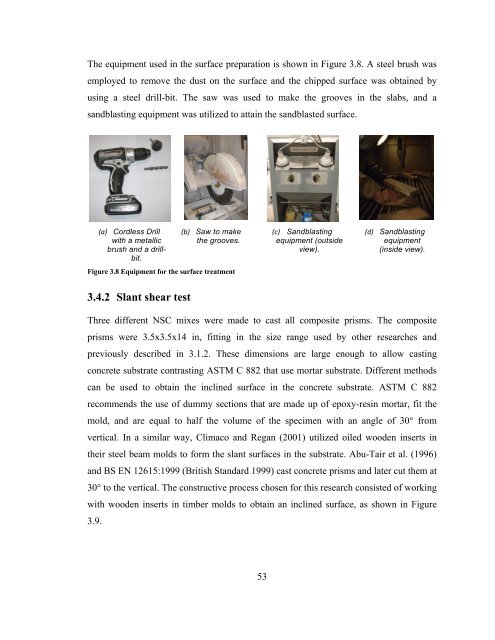
The equipment used in the surface preparation is shown in Figure 3.8. A steel brush w<strong>as</strong>employed to remove the dust on the surface and the chipped surface w<strong>as</strong> obtained byusing a steel drill-bit. The saw w<strong>as</strong> used to make the grooves in the slabs, and <strong>as</strong>andbl<strong>as</strong>ting equipment w<strong>as</strong> utilized to attain the sandbl<strong>as</strong>ted surface.(a) Cordless Drillwith a metallicbrush and a drillbit.(b) Saw to makethe grooves.Figure 3.8 Equipment for the surface treatment(c) Sandbl<strong>as</strong>tingequipment (outsideview).(d) Sandbl<strong>as</strong>tingequipment(inside view).3.4.2 Slant shear testThree different NSC mixes were made to c<strong>as</strong>t all composite prisms. The compositeprisms were 3.5x3.5x14 in, fitting in the size range used by other researches andpreviously described in 3.1.2. These dimensions are large enough to allow c<strong>as</strong>ting<strong>concrete</strong> substrate contr<strong>as</strong>ting ASTM C 882 that use mortar substrate. Different methodscan be used to obtain the inclined surface in the <strong>concrete</strong> substrate. ASTM C 882recommends the use <strong>of</strong> dummy sections that are made up <strong>of</strong> epoxy-resin mortar, fit themold, and are equal to half the volume <strong>of</strong> the specimen with an angle <strong>of</strong> 30° fromvertical. In a similar way, Climaco and Regan (2001) utilized oiled wooden inserts intheir steel beam molds to form the slant surfaces in the substrate. Abu-Tair et al. (1996)and BS EN 12615:1999 (British Standard 1999) c<strong>as</strong>t <strong>concrete</strong> prisms and later cut them at30° to the vertical. The constructive process chosen for this research consisted <strong>of</strong> workingwith wooden inserts in timber molds to obtain an inclined surface, <strong>as</strong> shown in Figure3.9.53