Modine: Installation And Service Manual - Alpine Home Air Products
Modine: Installation And Service Manual - Alpine Home Air Products
Modine: Installation And Service Manual - Alpine Home Air Products

Create successful ePaper yourself
Turn your PDF publications into a flip-book with our unique Google optimized e-Paper software.
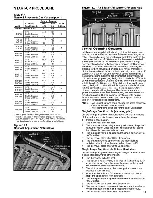
START-UP PROCEDURETable 11.1Manifold Pressure & Gas Consumption ➀Figure 11.2 - <strong>Air</strong> Shutter Adjustment, Propane GasMANIFOLDAIRSHUTTERMAINBURNERORIFICESNatural PropaneBTU/Cu. Ft. 1050 2500 No. ofModel Specific Gravity 0.60 1.53 OrificesManifold Pressure In. W.C. 3.5 10.0CFH 28.6 12.0PDP 30 Gal/Hr. Propane – .33 1Orifice Drill Size 38 52PDP 50BDP 50PDP 75BDP 75PDP 100BDP 100PDP 125BDP 125PDP 150BDP 150PDP 175BDP 175PDP 200BDP 200PDP 250BDP 250PDP 300BDP 300PDP 350BDP 350CFH 47.6 20.0Gal/Hr. Propane – .55 1Orifice Drill Size 30 45CFH 71.4 30.0Gal/Hr. Propane – .82 1Orifice Drill Size 21 39CFH 95.2 40.0Gal/Hr. Propane – 1.15 2Orifice Drill Size 30 45CFH 119.0 50.0Gal/Hr. Propane – 1.43 2Orifice Drill Size 26 43CFH 138.1 58.0Gal/Hr. Propane – 1.64 2Orifice Drill Size 21 39CFH 166.7 70.0Gal/Hr. Propane – 1.86 3Orifice Drill Size 28 43CFH 190.5 80.0Gal/Hr. Propane – 2.19 3Orifice Drill Size 25 42CFH 238.1 100.0Gal/Hr. Propane – 2.74 3Orifice Drill Size 18 36CFH 285.7 120.0Gal/Hr. Propane – 3.29 4Orifice Drill Size 21 39CFH 333.3 140.0Gal/Hr. Propane – 3.84 5Orifice Drill Size 23 41CFH 381.0 160.0PDP 400 Gal/Hr. Propane – 4.38 6Orifice Drill Size 25 42➀ Above gases based on average standards. Units can befurnished for gases of different values and specific gravities.(Gal./Hr. based on 60°F. 30" Hg., 91,500 BTU/Gal.) In Canada,refer to rating plate on side of unit for orifices at high altitude.Figure 11.1Manifold Adjustment, Natural GasMIXERTUBESBURNERRETAINING PINMANIFOLDMAINBURNERORIFICESMANIFOLD MOUNTINGSCREW AND PINMIXERTUBESControl Operating SequenceUnit heaters are supplied with standing pilot control systems asstandard or intermittent pilot systems with continuous retry as anoption. On standing pilot and mechanical modulation systems themain burner is turned off 100% when the thermostat is satisfied,but the pilot remains lit. For intermittent pilot systems, exceptmechanical modulation both the main burner and pilot burner areturned off 100% when the thermostat is satisfied. Standing pilotsystems, for both natural and propane gas, have a manually litpilot which stays lit until the gas valve is manually turned to the offposition. On a call for heat, the gas valve opens, sending gas tothe burner allowing the unit to fire. Intermittent pilot systems, forboth natural and propane gas, the ignition controller is 100% shutoffwith continuous retry. On a call for heat, the system will attemptto light the pilot for 70 seconds. If the pilot is not sensed for anyreason, the ignition control will wait for approximately six minuteswith the combination gas control closed and no spark. After sixminutes, the cycle will begin again. After three cycles, someignition controllers lockout for approximately one hour before thecycle begins again. This will continue indefinitely until the pilotflame is sensed or power is interrupted to the system. Refer totable 14.1 for control code descriptions.NOTE: Gas Control Options could change the listed sequenceof operation based on their function.The descriptions given are for the basic unit heater.Single-Stage Gas Controls (standing pilot)Utilizes a single-stage combination gas control with a standingpilot operator and a single-stage low voltage thermostat.1. Pilot is lit continuously.2. The thermostat calls for heat.3. The power exhauster relay is energized starting the powerexhauster motor. Once the motor has reached full speed,the differential pressure switch closes.4. The main gas valve is opened and the main burner is lit to100% full fire.5. The air mover starts after 30 to 90 seconds.6. The unit continues to operate until the thermostat issatisfied, at which time the main valve closes 100%.7. The air mover stops after 30 to 90 seconds.Single-Stage Gas Controls (intermittent pilot)Utilizes a single-stage combination gas, an ignition control, anda single-stage low voltage thermostat.1. The thermostat calls for heat.2. The power exhauster relay is energized starting the powerexhauster motor. Once the motor has reached full speed,the differential pressure switch closes.3. The pilot valve opens and the spark ignitor sparks in anattempt to light the pilot.4. Once the pilot is lit, the flame sensor proves the pilot andstops the spark ignitor from sparking.5. The main gas valve is opened and the main burner is lit to100% full fire.6. The air mover starts after 30 to 90 seconds.7. The unit continues to operate until the thermostat is satisfied, atwhich time both the main and pilot valves close 100%.8. The air mover starts after 30 to 90 seconds. 11
![Owner's Manual (General) [pdf] - Appliance Factory Parts](https://img.yumpu.com/50830858/1/184x260/owners-manual-general-pdf-appliance-factory-parts.jpg?quality=85)