Modine: Installation And Service Manual - Alpine Home Air Products
Modine: Installation And Service Manual - Alpine Home Air Products
Modine: Installation And Service Manual - Alpine Home Air Products

You also want an ePaper? Increase the reach of your titles
YUMPU automatically turns print PDFs into web optimized ePapers that Google loves.
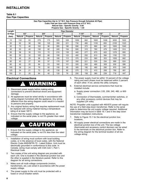
INSTALLATIONTable 8.1Gas Pipe CapacitiesGas Pipe Capacities (Up to 14” W.C. Gas Pressure through Schedule 40 Pipe)Cubic Feet per Hour with Pressure Drop of 0.3” W.C.Natural Gas - Specific Gravity - 0.60Propane Gas - Specific Gravity - 1.50LengthPipe DiameterOf Pipe 1/2" 3/4" 1" 1-1/4" 1-1/2" 2"(feet) Natural Propane Natural Propane Natural Propane Natural Propane Natural Propane Natural Propane10 132 83 278 175 520 328 1050 662 1600 1008 3050 192220 92 58 190 120 350 221 730 460 1100 693 2100 132330 73 46 152 96 285 180 590 372 890 561 1650 104040 63 40 130 82 245 154 500 315 760 479 1450 91450 56 35 115 72 215 135 440 277 670 422 1270 80060 50 32 105 66 195 123 400 252 610 384 1150 72570 46 29 96 60 180 113 370 233 560 353 1050 66280 43 27 90 57 170 107 350 221 530 334 990 62490 40 25 84 53 160 101 320 202 490 309 930 586100 38 24 79 50 150 95 305 192 460 290 870 548125 34 21 72 45 130 82 275 173 410 258 780 491150 31 20 64 40 120 76 250 158 380 239 710 447Electrical ConnectionsWARNING1. Disconnect power supply before making wiringconnections to prevent electrical shock and equipmentdamage.2. All appliances must be wired strictly in accordance withwiring diagram furnished with the appliance. Any wiringdifferent from the wiring diagram could result in a hazardto persons and property.3. Any original factory wiring that requires replacement mustbe replaced with wiring material having a temperaturerating of at least 105°C.4. Ensure that the supply voltage to the appliance, asindicated on the serial plate, is not 5% greater than ratedvoltage.CAUTION1. Ensure that the supply voltage to the appliance, asindicated on the serial plate, is not 5% less than the ratedvoltage.1. <strong>Installation</strong> of wiring must conform with local buildingcodes, or in the absence of local codes, with the NationalElectric Code ANSI/NFPA 70 - Latest Edition. Unit must beelectrically grounded in conformance to this code. InCanada, wiring must comply with CSA C22.1, Part 1,Electrical Code.2. Two copies of the unit wiring diagram are provided witheach unit. One is located in the electrical junction box andthe other is suppled in the literature packet. Refer to thisdiagram for all wiring connections.3. Make sure all multi-voltage components (motors,transformers, etc.) are wired in accordance with the powersupply voltage.4. The power supply to the unit must be protected with afused or circuit breaker switch.5. The power supply must be within 10 percent of the voltagerating and each phase must be balanced within 2 percentof each other. If not, advise the utility company.6. External electrical service connections that must beinstalled include:a. Supply power connection (120, 208, 240, 480, or 600volts).b. Connection of thermostats, summer/winter switches, orany other accessory control devices that may besupplied (24 volts).NOTE: Propeller units supplied with 460/575 power will requirethe use of a field step-down transformer. Refer to the serialplate to determine the unit supply voltage required. Additionalinformation may be found in table 16.1 and in the step downtransformer installation instructions.7. Refer to Figure 15.1 for the electrical junction boxlocations.8. All supply power electrical connections are made in theelectrical junction box of the unit. The low voltage(thermostat and accessory control devices) can be wiredto the terminals on the electrical junction box. Refer tothe wiring diagram for the terminal location of all lowvoltage wiring.8

![Owner's Manual (General) [pdf] - Appliance Factory Parts](https://img.yumpu.com/50830858/1/184x260/owners-manual-general-pdf-appliance-factory-parts.jpg?quality=85)